Advertisement
Quick Links
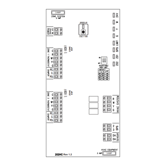
ZP2-HC-ESP Installation and Operation Instructions
3 AMP
ON
.
. .
OFF
PC
2
C
1
PO
3
ON
.
. .
OFF
PC
2
C
1
PO
3
Rev 1.2
OVERVIEW:
The ZP2-HC-ESP is a residential/light commercial
zone control panel that includes integrated ESP
static pressure control logic designed to eliminate
the need for a conventional bypass damper when
used with 3-wire zone dampers.
SEQUENCE OF OPERATION:
The panel allows a single HVAC unit to have up
to two separate zones. Each zone is controlled
by its own thermostat. When a zone thermostat
calls for heating or cooling, the zone not calling
will have its dampers powered closed, and the
zone calling will have its dampers powered
opened. The heating or cooling equipment will
also be brought on.
As zone dampers open and close, the ZPA-SPS
Static Pressure Sensor continuously monitors
the system static pressure. If the static pressure
goes above the static pressure setpoint, the
panel will send a signal to the non-calling zone
damper to start to open to a point where the
static pressure setpoint is maintained. The SPS
LED will come on with the non-calling zone LED
until the static pressure reaches setpoint. The
small amount of air allowed to bleed into non-
calling zone eliminates air noise and assures
proper airflow through the HVAC system. This
also prevents coil freeze up and high
temperature issues. When all calls are
1 Heat / 1 Cool - Auto Changeover
First Call Priority - Time Share
with Integrated ESP Static Pressure Module
SPEED UP
3 SEC = 1 MIN
1 2
3 AMP
satisfied, all zone dampers will go to the full open
position provided none of the thermostats are
calling for ventilation mode. If opposite calls take
place, the first zone to call receives priority. When
the first call is satisfied, the system will
changeover and take care of the opposite call. If
zones being served (heating or cooling) have not
been satisfied within 20 minutes while an opposite
call is taking place, the system will changeover.
When the zone is satisfied or 20 minutes has
elapsed, the system will again changeover if an
opposite call exists. This is referred to as Auto-
Changeover - First Call Priority - Time Share. In
the event of a tie, cooling will receive priority.
HIGH AND LOW LIMIT PROTECTION:
A ZPA-DTS Discharge Temperature Sensor
should be mounted on the discharge air plenum of
the HVAC unit and wired to the DA terminals on
the panel. The sensor is used for both high
(adjustable) and low (fixed) limit protection. The
high limit setting can be adjusted using the two
slide switches located on the panel. (See switch
location and settings on page 2) Low limit is fixed
at 45° F. When the discharge air temperature rises
above the high limit setting or falls below the low
limit setting, the panel will cycle the equipment off
while the fan continues to run. The LIMIT LED
blinks when high or low limit is reached. In cooling
mode, a 3 minute time delay is activated to
prevent short cycling of the equipment.
VENTILATION MODE:
Zone ventilation is established by the individual
zone thermostat fan setting. When no calls are
taking place, any thermostat set in the fan AUTO
mode will not receive ventilation air and its zone
damper will be closed. Any zone thermostat set in
the fan ON mode will receive ventilation air and its
zone damper will be opened. Heating or cooling
calls take priority over ventilation mode. The ESP
function will continue to maintain the system static
pressure by modulating open the non-calling
ventilation zone as required.
POWER REQUIREMENTS:
The panel is powered by a single 24VAC, 40VA
transformer. Never use the equipment
transformer.
1
Advertisement

Related Manuals for iO HVAC Controls ZP2-HC-ESP-KIT


Summary of Contents for iO HVAC Controls ZP2-HC-ESP-KIT
- Page 1 ZP2-HC-ESP Installation and Operation Instructions 1 Heat / 1 Cool - Auto Changeover First Call Priority - Time Share with Integrated ESP Static Pressure Module satisfied, all zone dampers will go to the full open 3 AMP position provided none of the thermostats are SPEED UP calling for ventilation mode.
- Page 2 ZP2-HC-ESP Panel Layout SPEED UP BUTTON 3 AMP FUSE PROTECTS 3 AMP PRINTED CIRCUIT BOARD 24 VOLT POWER LED 1ST STAGE HEATING LED SPEED UP 1ST STAGE COMPRESSOR LED 24 VOLTS FAN LED 3 SEC = 1 MIN LIMIT LED (ON WHEN DAS IS DETECTED.
- Page 3 ZP2-HC-ESP TERMINAL DESIGNATIONS TRANSFORMER 24VAC POWER C (24V COMMON) R (24V HOT) W (1ST STAGE HEAT) Y1 (1ST STAGE COMPRESSOR) G (FAN) POWER CLOSE COMMON POWER OPEN C (24V COMMON) R (24V HOT) W (1ST STAGE HEAT) Y1 (1ST STAGE COMPRESSOR) R (24V HOT) G (FAN) W (1ST STAGE HEAT)
-
Page 4: Adjustable High Limit
ZP2-HC-ESP LED STATUS DEFINITIONS 24 VOLT POWER LED 1ST STAGE HEATING LED 1ST STAGE COMPRESSOR LED FAN LED LIMIT LED STATIC PRESSURE SENSOR LED ZONE 1 DAMPER LED ZONE 2 DAMPER LED ADJUSTABLE HIGH LIMIT High Limit adjustment switches are located on the panel. - Page 5 INSTALLING AND WIRING THE ZP2-HC-ESP land the wires to the screw terminals marked DA MOUNTING THE ENCLOSURE: on the panel. Carefully remove the panel from the shipping carton. Remove the cover and any packing material. Locate the panel on a flat, non- condensating, vertical surface near the indoor unit that will facilitate ease of wiring and service access.
- Page 6 INSTALLING AND WIRING THE ZP2-HC-ESP WIRING THE TRANSFORMER: Once the cooling cycle is energized, the Wire the separate 24 Volt transformer to the following panel LEDs should be lit: 24VAC POWER ‘R’ and ‘C’ terminals. Use conventional 18-2 thermostat wire. After removing the outer jacket, strip approximately 1/8”...
- Page 7 ZP2-HC-ESP SPECIFICATIONS: FIELD WIRING TERMINALS: Enclosure: Zone Thermostats: Plastic 24Vac (Common) 24Vac (Hot) First Stage Heat Panel Dimensions: First Stage Compressor Height: 9.5” Width: 6.75” Depth 2.25” HVAC System: 24Vac Equipment Hot PC Board Mounting: First Stage Heat Individual snap mounted to enclosure base First Stage Compressor Operating Temperature Rating: -40°...
- Page 8 SPECIAL ADDENDUM USING ESP ZONING PANELS WITH GAS FURNACES HAVING DIRECT SPARK IGNITION (DSI) DSI functions by creating a rapid series of high-voltage electric sparks, which means DSI controls generate electromagnetic interference (EMI) during their trial for ignition. This electronic noise can sometimes interfere with ESP zoning panels as well as other nearby electronic components and even with the ignition control itself.
- Page 9 New HVAC equipment using A2L refrigerants (R-32, R-454B, etc.) may incorporate a Refrigerant Leak Detection System (RDS) as an added safety measure. iO HVAC Controls ESP series zone panels can accept a signal from the RDS in order to drive open all dampers when a leak is detected.
Need help?
Do you have a question about the ZP2-HC-ESP-KIT and is the answer not in the manual?
Questions and answers