
Related Manuals for Charmeg Sherpa M43


Summary of Contents for Charmeg Sherpa M43
- Page 1 Sherpa M43 Full Guide Intelligent Solar Controller Full installation and use manual Full installation and use manual -v1 Sherpa_M43_Full_EN_1.docx...
- Page 2 Full installation and use manual -v1 Sherpa_M43_Full_EN_1.docx...
- Page 3 Detailed installation & use guide Solar Thermal – The natural form of pure energy In 90 minutes, the sun irradiates the earth with the energy that humanity needs for an entire year. This in itself is an exciting element to understand the amount of energy lost unexploited and could solve the energy problem universally and entirely.
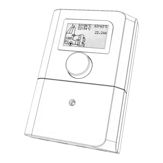
- Page 4 Features • Illuminated graphic display • Multilingual menu • Handling via RotorFlex rotary-push button • Temperature measurement and imaging -40°C...+300°C. • Control the collectors’ circulators • Auxiliary source control (e.g. burner, electrical resistance) with time program • DHW recirculation control •...
-
Page 5: Safety Instructions
Safety Instructions The device has been designed in accordance with modern specifications and meets the appropriate requirements to operate without problems for years. All safety instructions for such devices have been taken into account in its design. Please read this installation and use guide carefully. -
Page 6: Installation
1. Installation 1. Installation - Support The device can be mounted on a wall or in a hydraulic station recess with the appropriate dimensions. On the back side are provided suitable holes that are 126mm apart so that it is simple and easy to support and align. Carefully select the point so that it does not get wet and there is enough space for the required wiring. - Page 7 Figure2 Place the sensors in a specific diameter probes to properly measure the temperature and perform effective control. The sensors must be of type PS301k0 (PT1000). The maximum device-sensor distance is 40m. The connection can be made with a simple two-wire multi thread cable e.g., 2x0.75mm2. Use independent cables to connect sensors or PWM signals and relays or power voltage.
- Page 8 In systems with more than one PWM circulator (e.g. draft No6, No7, No9, etc.) the output of a single circulator (Black Conductor) PWM is allowed to connect to the PWM IN contact and will only monitor its condition. The device accepts and produces PWM signals according to DIN IEC60469-1. After the installation is complete, install the front panel cover.
-
Page 9: Operation
2. Operation 1. Device description The device has an illuminated graphic display and rotary push control (RotorFlex). All manipulations and adjustments are performed through them. If it is powered for the first time, it will ask you to enter the contact language on the date and time. - Page 10 2. Setup Pressing the control briefly switches to the "Main Menu". From this you can choose one of the available sub-menus that are distributed according to the content of the functions they manage. These sub-menus may provide access to parameters or other sub-menus. By turning the control, we scroll through the available options, pressing briefly, Figure5 confirming and pressing and holding, returning to the previous menu or submenu.
- Page 11 From any menu or sub-menu point, the device will return on its own to the home screen and will continue to operate if left for a while without pressing or rotating its knob. The device settings are stored in an non-volatile memory which is not altered by the power cut-off.
- Page 12 4. Analysis Menu/ Sub Menu The contents of each menu and sub-menu accessed via the control panel and the display are then analyzed. Main Menu Parameter Explanation The hydraulic design and parameters related to circulators, the Hydraulic scheme type of collectors and the priority in charging the hot water stores are selected Provides access to parameters related to the operation of the Differential No1...
- Page 13 Sub-menu: Hydraulic configuration Adjusting Parameter Explanation Pre-set Limits Parameter that determines the form of Installation plan 1…20 hydraulic connections in the installation. For circulators with PWM input, it determines the percentage of PWM signal PWM out max 25%...100% for which the circulator operates at maximum speed.
- Page 14 Temperature difference between two sensors 8°C ΔT off for which the differential controller will 1°C…15°C switch off the circulator. The time delay between reaching a 0sec. Activation delay temperature difference greater than “ΔΤ on” 0sec…60sec. until the circulator is activated. Anti-freeze Option to enable freeze protection.
- Page 15 Collector temperature above which the Pipe protection 150°C circulator is stopped in order to protect 100°C…150°C temp intermediate piping. Sub-menu: Heating Support Adjusting Parameter Explanation Pre-set Limits 2 time periods within 24 hours are set in which 00:00- Support the temperature of the water used is 00:00…23:00 periods monitored and if it is not satisfactory, the...
- Page 16 Sub-menu: Special functions -> Heat gain Parameter Explanation Adjusting Limits Pre-set Option to activate the energy gain Activation No…Yes measurement function. Determines which of the S2, S3, S4 Return sensor sensors will be that of the low 2…4 temperature during measurement. The constant flow of the thermal Maximum carrier in constant speed systems and...
- Page 17 Sub-menu: Statistics Parameter Explanation The energy gain measurement is displayed in MWh (megawatt Heat gain hours) and kWh (kilowatt hours). The date and time that became the most recent (active or Last disinfection passive) disinfection is displayed. Runtime Displays the total running time of the R1-R3 relays. Displays the maximum and minimum temperature recorded Temperature extremes for each sensor (S1-S4).
- Page 18 Information Information about the device version and its manual is presented. [18] Full installation and use manual -v1 Sherpa_M43_Full_EN_1.docx...
-
Page 19: General Operation
3. General operation Figure7 1. Differential thermostat The basic function of the device is that of the differential thermostat for forced- circulation solar thermal systems. The purpose of the differential thermostat is to remove the thermal energy from the collector and store it in the container with the greatest possible efficiency and maximum safety. - Page 20 beyond which the circulator is stopped in order to protect the intermediate hydraulic components. 4. Reverse cooling Reverse cooling is a useful feature that, if selected, helps protect the system from overheating. It is activated when the collector temperature is at least 5°C lower than that of the store and provided that the store has exceeded the maximum charge temperature.
-
Page 21: Hydraulic Configuration
4. Hydraulic Configuration 1. Installation plan The device offers the option to choose between 20 different hydraulic configurations in each of which 2 or more sensors are involved (S1, S2, S3, S4), one to three relays (R1, R2, R3), up to 3 virtual differential thermostats and one limit thermostat. Proper matching of the actual hydraulic installation and the design is crucial for the proper operation, performance and safety of the system. - Page 22 Speed Max RPM Min RPM 100% Maximum Minimum Figure8 6. PWM input type This parameter is used when the solar field circulator has a status data output (according to PWM standard) to the controller. The available options are: No = circulator without output status data Wilo = circulator with an output in accordance with the Wilo standard Grundfos = circulator with outlet in accordance with the Grundfos standard 7.
- Page 23 9. Vacuum tube repeat period Determines when the collector circulator will be activated during vacuum collector operation. 10. Refill time It is used in drain-back systems and refers to the time that the collector’s circulator will operate at maximum speed in order to draw a thermal carrier from the runoff vessel and achieve replenishment of the installation.
-
Page 24: Special Functions
5. Special Functions 1. Thermal disinfection The (active) thermal disinfection function can be activated in hydraulic configurations using an auxiliary source to heat the domestic hot water. Its purpose is to contribute to the effort to limit bacteria such as Legionella in water. When active thermal disinfection is selected, the device monitors the temperature of the water used and when time is elapsed equal to the disinfection period, activates the auxiliary source with thermostatic control at temperatures up to the selected disinfection... - Page 25 • the type of thermal carrier (type of chemical compound and concentration by volume) The flow sensor is always S1. The return sensor can be selected by the installer and entered in the corresponding menu. The flow is regulated by the electronic control of the circulator and the correct calculation requires that the maximum flow is entered in the corresponding menu.
-
Page 26: Heating Support
When the heat rejection function is selected, the symbol appears on the descending tubing from the collector. When the function is activated, the symbol is replaced by the The device has the ability to detect and manage the excess heat of the collector. In order to achieve this, the corresponding feature must be activated and the collector temperature above which the energy balance of the collector-container is considered to have been overturned and the collector can now generate more energy than can be... - Page 27 always having the meaning of the last backup before water is declared unsuitable for use due to low temperature. The purpose of heating support is to always provide hot water to the installation, taking advantage of the available sources. For this reason, it can happen that the auxiliary source and the collector circulator are activated simultaneously.
- Page 28 7. Detection and recording of errors The device incorporates a series of sophisticated features related to the detection, troubleshooting and recording of errors that may occur during its operation. Their purpose is to protect the installation and inform the technician to lead to their short resolution.
- Page 29 reconnected, the event log will record, in addition to the type of problem, the time it occurred and the time it was fixed. Figure10 In the event of a critical error (all errors except 6=Recoverable memory error), the device shuts down its normal operation and switches to a security state, leading its outputs to an appropriate state with the main purpose of protecting the system.
- Page 30 PS301k0 sensor Temperature-ohmic resistance mapping table Temperature Resistance 0 °C 1000 Ohms 10 °C 1040 Ohms 20 °C 1080Ohms 30 °C 1120 Ohms 40 °C 1160 Ohms 50 °C 1200 Ohms 60 °C 1230 Ohms 70 °C 1270 Ohms 80 °C 1310 Ohms 90 °C 1350 Ohms...
-
Page 31: Installation Plans
8. Installation plans The 20 hydraulic configurations of a solar power plant are then presented. In each configuration there is a table that gives a lot of information about the operation of the installation and its basic structural elements such as thermal storage tanks, collectors, sensors etc. - Page 32 Plan No1 Sensors Control unit Relationship Exit Differential No1 Operation Thermal disinfection Available (passive) Heat rejection Available (via R3) Simple differential thermostat function for charging the store via the collector circulator activated by relay R1. (*) the connections of the PWM cable of the circulator are described in the section "Electrical connections".
- Page 33 Plan No2 Sensors Control unit Relationship Exit Differential No1 Differential No2 Operation Thermal disinfection Available (passive) Heat rejection Available (via R3) Differential thermostat function for charging the first (left) store via the collector circulator activated by relay R1. The second store is charged by differential control from the first via the circulator R2.
- Page 34 Plan No3 Sensors Control unit Relationship Exit Differential No1 Heating Support Operation Thermal disinfection Available (active via R2) Heat rejection Available (via R3) Differential thermostat function for charging the storer via the collector circulator activated by relay R1. If the solar activity is not enough, the store is charged by thermal support from an external source e.g., boiler, resistance, heat pump activated by relay R2 with simple thermostatic control.
- Page 35 Plan No4 Sensors Control unit Relationship Exit Differential No1 Differential No2 Operation Thermal disinfection Available (passive) Heat rejection Available (via R3) In this plan priority is the rapid heating of the upper part of the store from which the consumption is made.
- Page 36 Plan No. 5 Sensors Control unit Relationship Exit Differential No1 Differential No2 Operation Thermal disinfection Available (passive) Heat rejection Available (via R3) In this design priority is the quick heating of the left-hand store. When it has been sufficiently heated, the energy is directed to the right-hand store.
- Page 37 Plan No6 Sensors Control unit Relationship Exit Differential No1 Differential No2 Operation Thermal disinfection Available (passive) Heat rejection Available (via R3) This design can work with or without priority charging in the stores. If priority is selected, then the left store is charged first and then the right, that is, the sequential charge is followed.
- Page 38 Plan No7 Sensors Control unit Relationship Exit Differential No1 Differential No2 Operation Thermal disinfection Available (passive) Heat rejection Available (via R3) This design is applied in cases of two collector fields with different orientation. Its function is based on the charging of the store from any collector field this is possible or even from both at the same time.
- Page 39 Plan No8 Sensors Control unit Relationship Exit Differential No1 Differential No2 Operation Thermal disinfection Available (passive) Heat rejection Available (via R3) In this design, a solar thermal system coexist with a source of support of non-stable potential e.g. wood boiler, hydrothermal fireplace, etc..
- Page 40 Plan No9 Sensors Control unit Relationship Exit Differential No1 Differential No2 Differential No3 Operation Thermal disinfection Available (passive) Heat rejection Not available This plan can work with or without priority charging in the stores. If priority is selected, then the left store is charged first, then the middle and then the right, followed by the sequential charge.
- Page 41 Plan No10 Sensors Control unit Relationship Exit Differential No1 Differential No2 Heating Support Operation Thermal disinfection Available (active via R3) Heat rejection Not available This design is applied in cases of two collector fields with different orientation. Its function is based on the charging of the store from any collector field this is possible or even from both at the same time.
- Page 42 Plan No11 Sensors Control unit Relationship Exit Differential No1 Differential No2 Heating Support Operation Thermal disinfection Available (active via R3) Heat rejection Not available This plan is applied in cases of two collector fields with different orientation. Its function is based on the charging of the store from any collector field this is possible or even from both at the same time.
- Page 43 Plan No12 Sensors Control unit Relationship Exit Differential No1 Heating Support Operation Thermal disinfection Available (active via R2) Heat rejection Available (via R3) The design includes simple solar thermal system and auxiliary source (boiler, resistance, heat pump) with a sensor in the stores. It is based on the differential thermostat function for charging the store via the collector circulator activated by relay R1.
- Page 44 Plan No13 Sensors Control unit Relationship Exit Differential No1 Differential No2 Heating Support Operation Thermal disinfection Available (active via R3) Heat rejection Not available This plan can work with or without priority charging in the stores. If priority is selected, then the right store is charged first and then the left, that is, the sequential charge is followed.
- Page 45 Plan No14 Sensors Control unit Relationship Exit Differential No1 Differential No2 Operation Thermal disinfection Available (passive) Heat rejection Available (via R3) In this plan it is applied in cases of solar thermal system in combination with boiler and direct driving of consumption from the boiler.
- Page 46 Plan No15 Sensors Control unit Relationship Exit Differential No1 Operation Thermal disinfection Not applicable Heat rejection Available (via R3) This design is based on the simple differential thermostat function to directly charge the pool via the collector circulator activated by relay R1. (*) the connections of the PWM cable of the circulator are described in the section "Electrical connections".
- Page 47 Plan No16 Sensors Control unit Relationship Exit Differential No1 Differential No2 Operation Thermal disinfection Not applicable Heat rejection Available (via R3) This design is based on the pool charging function through heat exchanger and double differential control. The determination of suitable heat transfer conditions to the pool is initiated by the differential thermostat No1 that activates relay R1.
- Page 48 Plan No17 Sensors Control unit Relationship Exit Differential No1 Heating Support Differential No2 Operation Thermal disinfection Available (active via R3) Heat rejection Not available This design provides a store charging function, boiler assistance function and complete recirculation control of hot water use.
- Page 49 Plan No18 Sensors Control unit Relationship Exit Differential No1 Heating Support Differential No2 Operation Thermal disinfection Available (active via R3) Heat rejection Not available In this plan it is applied in cases of solar thermal system in combination with a boiler for charging the water of the container for heating spaces.
- Page 50 Plan No19 Sensors Control unit Relationship Exit Differential No1 Heating Support Differential No2 Operation Thermal disinfection Available (active via R3) Heat rejection Not available In this plan it is applied in cases of solar thermal system in combination with boiler and other alternative source of non-constant capacity (e.g.
- Page 51 Plan No20 Sensors Control unit Relationship Exit Differential No1 Differential No2 Operation Thermal disinfection Available (active via R3) Heat rejection Not available In this design priority is the quick heating of the right-hand store. When it has been sufficiently heated, the energy is directed to the left-hand store.
- Page 52 Terms of use Copying and reprinting of drawings, photographs and text of the manual without the consent of the company is prohibited. Charmeg, konigsol, AirLink, RotorFlex are registered names that protected under trademark law. Wilo, Grundfos are registered names of other companies.
- Page 53 Notes [53] Full installation and use manual -v1 Sherpa_M43_Full_EN_1.docx...
- Page 54 [54] Full installation and use manual -v1 Sherpa_M43_Full_EN_1.docx...
- Page 55 [55] Full installation and use manual -v1 Sherpa_M43_Full_EN_1.docx...
- Page 56 145 Attaleias str., Nikea, Athens P.C GR184 53 Tel. +30 210 56 93 111 Fax. +30 210 56 93 093 info@charmeg.gr www.charmeg.gr [56] Full installation and use manual -v1 Sherpa_M43_Full_EN_1.docx...
Need help?
Do you have a question about the Sherpa M43 and is the answer not in the manual?
Questions and answers