Table of Contents
Advertisement
Quick Links
Advertisement
Table of Contents

Related Manuals for SolidWELD Multipro 200 SP

Summary of Contents for SolidWELD Multipro 200 SP
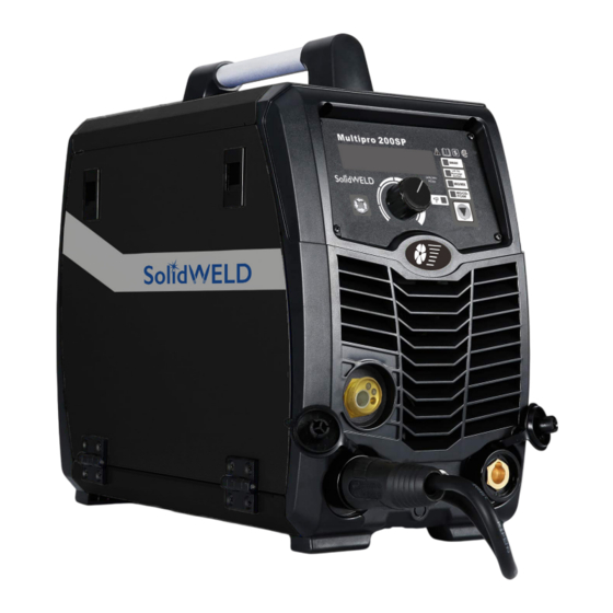
- Page 1 Multipro 200 SP Operating manual...
- Page 2 Congratulations on the purchase of your new welding machine! For your safety and the safety of others, please read the manual carefully before operating the unit. The operating manual must always be available near the welding machine. Announcement The contents of this manual are updated as required, as product changes are made. The manual is only used as operation guide, unless otherwise indicated.
-
Page 3: Table Of Contents
CONTENTS 1..SAFETY PRECAUTIONS..........................3 2..PRODUCT DESCRIPTION..........................8 3..TECHNICAL PARAMETERS........................... 9 4..INSTALLATION INSTRUCTION........................10 5..PANEL FUNCTION ILLUSTRATION......................13 6..RISKS & PREVENTIVE MEASURES......................19 7..POTENTIAL OPERATING PROBLEMS......................20 8..DAILY MAINTENANCE...........................21 9..DAILY CHECKING............................22 10..TROUBLESHOOTING AND FAULT FINDING................... 24 11.. -
Page 5: Safety Precautions
SAFETY PRECAUTIONS Safety Definitions This indicates that neglecting safety warnings may result in serious damage or injury, including death. This indicates that neglecting safety warnings may result in minor injury to WARNING personnel or property damage. This indicates that neglecting safety warnings may result in equipment failure or damage. - Page 6 Beware of Electric Shocks Before welding, the yellow-green grounding wire in the power line must be grounded and the insulation of the welding cable must be ensured. During welding operation, do not touch live parts such as workbench, welding parts, earth clamp, electrode holder or welding torches.
- Page 7 Welding Sparks May Cause Fire or Explosion Corresponding protective measures should be taken in the welding area to avoid fire caused by welding sparks. Do not carry out welding operations in degreasing, cleaning and spraying areas. Do not weld gas-filled pipes, sealing grooves (tanks) and other devices, otherwise explosions or fires are likely to occur.
- Page 8 Avoiding Electromagnetic Interference Users should ensure that the welding power supply and other equipment in the environment do not produce electromagnetic interference, otherwise corresponding shielding and protection measures should be taken. According to the manufacturer's suggestion, the power source should be connected to the main power supply line.
- Page 9 equipment before hoisting. When moving the power source on the ground, fix the cylinder with a strap or chain to prevent tipping and injury. If the wire feeder is hoisted by lifting eyes for welding, it is necessary to ensure that it is fastened and stable.
-
Page 10: Product Description
PRODUCT DESCRIPTION The Multipro 200SP applies the most advanced inverter technology in the world. The principle of inversion is to transform the power frequency of 50Hz/60Hz into direct current and invert it into high frequency (50KHz) through high-power device IGBT, then perform voltage-drop and commutation with the output high-power DC power supply via Pulse Width Modulation (PWM). -
Page 11: Technical Parameters
TECHNICAL PARAMETERS Type Multipro 200SP Item 1 phase 230V15% 1 phase 115V15% Power voltage (V) Frequency (Hz) 50/60 50/60 32.7 (MIG) 24 (MIG) Maximum rated input current (A) 26.7 (TIG) 17.2 (TIG) 32.2 (SMAW) 24.5 (SMAW) No-load voltage (V) 35-200 (MIG) 40-90 (MIG) Output current adjustment (A) 15-180 (TIG) -
Page 12: Installation Instruction
INSTALLATION INSTRUCTION The welding equipment is equipped with voltage compensation device. It ensures the normal operation of the machine during voltage fluctuations (±15% of rated voltage). It is suggested to use larger cable sizes, in order to reduce voltage drops during work requiring long cables.. - Page 13 Installation for MIG setup with optional spool gun NOTE: Ensure that all power to machine is turned off before connecting the spool gun. Connect the gas cylinder to the regulator. Select correct shielding gas for the application. Plug spool gun connection (A1) into output connection (1).
- Page 14 Installation for TIG process Connect the gas cylinder to the regulator. Select correct shielding gas for the application. Connect gas hose (A2) to the regulator. Connect the dinse plug (A1) of the TIG torch to negative (4) terminal of the front panel, and fasten it clockwise.
-
Page 15: Panel Function Illustration
PANEL FUNCTION ILLUSTRATION Multifunctional Data Display Data Selection Key Under MMA mode: can open or close VRD function by long press on the data selection key. Under MIG mode: can select parameters and choose the welding mode (2T/4T) by pressing the Data Selection Key. - Page 16 Operation instruction: 1) The starting up display Switch on the welding power source, the front panel displays as Fig.1. After the Multifunctional Data Display (or any key or knob on front panel) flashes for 5 seconds, the machine enters into the welding mode that saved before the last shutdown.
- Page 17 Adjusting parameters: In MIG mode, you can adjust the voltage and inductance. By default, you can adjust the wire feeding speed. Press the Data Selection Key for the first time, the Multifunctional Data Display shows as Fig.4. The preset welding voltage is adjustable within a range of ±20%. Press the Data Selection Key once again.
- Page 18 has stopped. After 2 seconds, the Multifunctional Data Display redisplays the preset current. Fig.8 Status when welding is stopped in MIG Mode 3) Operation instruction under LIFT TIG mode. After making sure the torch is not operating, press the Function Switch Key to select the LIFT TIG mode.
- Page 19 4) Operation instruction under MMA mode. Set welding mode: After making sure the torch is not operating, press the Function Switch Key to select MMA mode.,The SMAW indicator lights up when the machine enters into MMA mode. VRD function: Press the Data Selection Key for 3 seconds, the VRD function is enabled and will reduce open circuit voltage to a safe limit (Fig.11).
- Page 20 Error display: 1) Error display of wire feeder The panel displays as Fig.14 when the wire feeder is malfunctioning. The Multifunctional Data Display flashes continuously, indicating the machine cannot work normally. Please restart the machine. The panel will display the parameters that were set before malfunction occurrence. Fig.14 Error display of wire feeder 2)...
-
Page 21: Risks & Preventive Measures
RISKS & PREVENTIVE MEASURES Environment 1) The machine must be operated under dry air conditions and a maximum humidity level of 90%. 2) Ambient temperature must be between -10 to 40 degrees centigrade. 3) Avoid welding in high temperatures, under the sun or rain. Avoid contact between water and appliance. -
Page 22: Potential Operating Problems
POTENTIAL OPERATING PROBLEMS The phenomenon listed below may happen due to relevant accessories used, welding material, surroundings and power supply. Please improve surroundings and avoid these problems. A. Arc starting difficulty. Arc interruption happens easily: 1) Examine whether grounding wire clamp contacts with the workpiece well. 2) Examine whether each joint has improper contact. -
Page 23: Daily Maintenance
DAILY MAINTENANCE WARNING! Cut off the power completely before all maintenance, repair work. Make sure to pull out power plug before opening the case. 1. Remove dust regularly with dry compressed air. Remove dust at least once a month if the welding machine is used in very dusty or polluted areas. -
Page 24: Daily Checking
DAILY CHECKING WELDING POWER SUPPLY Position Check points Remarks 1. Condition of operation, transfer and installation of switches Control panel 2. Check the power indicator If abnormal noise Cooling fan 1. Check if there is wind and if the sound is normal and no wind, check the inside of the fan 1. -
Page 25: Wire Feeder
WIRE FEEDER Position Check points Remarks Pressure Appropriate positioning of the pressure Poor wire guidance and unstable Accumulation of dirt or residue in the Clean the residue, find the source mouth of the tube of the problem and solve it Wire lead Wire diameter matches the tube’s inner If unmatched, may cause residue... -
Page 26: Troubleshooting And Fault Finding
TROUBLESHOOTING AND FAULT FINDING Notes: The following operations must be performed by qualified electricians with valid certifications. Before performing any maintenance or repair work, it is recommended to contact your local distributor to verify the required qualifications. Failures and solutions: Failure Solution 1. -
Page 27: Diagnosis Of Manufacturing Defects
DIAGNOSIS OF MANUFACTURING DEFECTS A new machine may have faults or manufacturing defects, such as unstable arc or poor welding quality. Although it is still too early to judge whether the machine is defective or not. If the above-mentioned problems occur with a new machine, a verification process should be followed before returning it to the retailer. - Page 28 Initial problems diagnosis Abnormal Items Check points and Maintenance 1. Wire spool does not match the diameter of wire in guide tube 2. Defective wire feeding wheel or groove blocked Wire Feeder 〇 〇 〇 〇 〇 3. Handle too tight or loose 4.
-
Page 29: Recommended Welding Parameters
RECOMMENDED WELDING PARAMETERS The welding current and welding electrode parameters are generally set as follows. Electrode φ2.5 φ3.2 φ4.0 φ5.0 specification Welding current 50-90A 90-130A 140-210A 190-270A MIG welding parameter variables The values listed in the following table are the general parameters under standard condition. Material Wire Interval... - Page 30 Material Wire Current Voltage Welding Wire Gas flow rate thickness diameter speed extension (A) (V) (L/min) (mm) (mm) (cm/min (mm 0.8,0.9 60~80 16~17 40~50 0.8,0.9 80~100 19~20 40~55 10~15 1.0,1.2 120~160 20~22 35~45 10~15 10~15 1.0,1.2 150~180 21~23 30~40 10~15 20~25 Material Wire...
-
Page 31: Circuit Diagram
CIRCUIT DIAGRAM... -
Page 32: Exploded View And Parts List
EXPLODED VIEW AND PARTS LIST Description Central socket, European connector, hexagonal copper core, R-24-030000-10-A0 copper head 20mm + copper tail 75mm R-32-101004-464-A0 Control panel label R-19-101691-01-A1 Right cover, EC1 R-19-100691-01-A1 Movable side plate, EC1 appearance, with hinge hole and push lock R-07-020000-12-00 Power switch (seesaw), HY12-9 Kedu, 20A/250v, red PCBA, single board computer motherboard (patch), including... - Page 33 Description Insulating board, with base plate RN0052-06A, rectangular, 176.6 * R-23-010500-85-A0 123.5mm Insulating sheet, equipped with control board PH01-113, R-23-010800-47-A0 rectangular, 285 * 218mm R-23-020602-43-A0 Air duct board, radiator left, rectangular, 185 * 129mm R-23-020602-44-A0 Air duct plate (upper), 79 * 30mm Tablet pressing, pressing 2 field pipes, arched, l = 25.5mm, with R-23-040000-106-A0 combination screw M4 * 16...
- Page 36 www.shop.messer-ca.com Visit your local Messer store or go to to find a store near you. If you have any queries or require additional information please contact a 1-888-256-7359 Customer Service Representative at who will be happy to assist you. Our retail stores across the country serve a variety of customers, stores are open Monday through Friday, from 8:00 AM to 5:00 PM.
Need help?
Do you have a question about the Multipro 200 SP and is the answer not in the manual?
Questions and answers