
Summary of Contents for Shadin Avionics Miniflo-L 91204XT-D
- Page 1 Miniflo-L Digital Fuel Management System RS-232 output format with interface to LORAN-C and GPS receivers OPERATING MANUAL Single and Twin Engine Indicators For P/N: 91204XT-D Pub No: OP91204E Revision A...
- Page 3 Miniflo-L Operating Manual Record of Revisions Revision Letter Date Description Initial Release of P/N OP01204E 18 Aug 2009 Clarified configuration data for GPS/Loran input on page 25. Pub No: OP91204E Page 1 Rev. A...
-
Page 4: Table Of Contents
Miniflo-L Operating Manual TABLE OF CONTENTS 1. GENERAL DESCRIPTION ..........4 THE SYSTEM PROVIDES ..............5 1.1.1 SPECIFIC RANGE ................5 1.1.2 FUEL TO DESTINATION ..............5 1.1.3 FUEL RESERVE ................5 1.1.4 ENDURANCE ................... 5 1.1.5 FUEL FLOW ..................6 1.1.6 FUEL USED .................. - Page 5 Miniflo-L Operating Manual 3.1.7 FUEL RESERVE ................16 3.2.1 NOT ENOUGH FUEL ..............16 3.2.2 RESERVE FUEL WILL BE USED ..........16 3.2.3 LOW ENDURANCE ............... 17 3.2.4 LOW FUEL REMAINING .............. 17 4. EMERGENCY PROCEDURES ........17 5. ERROR MESSAGES ............18 6.
-
Page 6: General Description
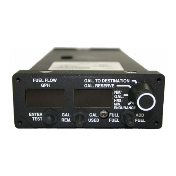
Miniflo-L Operating Manual Miniflo-L Although not required by the FAA, it is recommended that this manual be attached to the FAA-approved Flight Manual, or always kept on board for reference. 1. GENERAL DESCRIPTION Miniflo-L™ is a Digital Fuel Management System designed to provide complete fuel management information under real flight conditions without any manual entry of data (after entry of the initial fuel on board information). -
Page 7: The System Provides
Miniflo-L Operating Manual THE SYSTEM PROVIDES 1.1.1 SPECIFIC RANGE Specific Range (NM/GAL) = Ground Speed (Kt.)/Fuel Flow per hour. This is an indication of how efficient the cruise is and the optimum cruise speed can be determined by selecting the power setting, which yields the highest nautical miles per gallon. -
Page 8: Fuel Flow
Miniflo-L Operating Manual 1.1.5 FUEL FLOW The system provides a digital readout of the fuel per hour to a tenth of a gallon up to 100 gallons and to the nearest gallon above 100 gallons. For the pounds version, the readout is to the nearest pound up to 999 lbs./hour and to the nearest 10 lbs. -
Page 9: System Components
Miniflo-L Operating Manual SYSTEM COMPONENTS The system consists of three (3) basic units: the fuel flow transducer, the navigation receiver (Loran-C or GPS) and the panel mounted unit. 1.2.1 FUEL FLOW TRANSDUCER The fuel flow transducer mounted in the fuel line measures the flow of fuel and generates electrical pulses directly proportional to the fuel flow. -
Page 10: Test Function
Miniflo-L Operating Manual TEST FUNCTION Diagnostic software is built into the system. To activate it, press the ENTER/TEST button. All of the digits will be sequentially on in a rotating pattern for ten seconds. If the test is successful, the word “Good”... -
Page 11: Preflight Procedures
Miniflo-L Operating Manual PREFLIGHT PROCEDURES Miniflo-L™ is a fuel flow measuring system and NOT a quantity- sensing device. A visual inspection and positive determination of the usable fuel in the fuel tanks is a necessity. Therefore, it is imperative that the determined available usable fuel be manually entered into the system. -
Page 12: Preflight Check
Miniflo-L Operating Manual Move the REM/USED toggle switch to the REM position to increment the full fuel number or to the USED position to decrement the number. (The longer you hold the switch in position, the faster the number will be updated.) After reaching the correct total usable fuel figure, press the ENTER/TEST button and the computer will store that number as full fuel. -
Page 13: Fuel Added
Miniflo-L Operating Manual Lt ( ): Loran or GPS type appears in the left window (without signal, will display “LOF”). The distance to waypoint or destination is displayed as shown on the Loran-C or GPS receiver to check the Data Interface Integrity (not available without signal). -
Page 14: Fuel Tanks Full
Miniflo-L Operating Manual FUEL TANKS FULL There are two methods to enter full fuel: the ramping method and the FULL/ADD toggle switch method. Ramping Method • Move the REM/USED toggle switch to the REM position and hold. • Press the ENTER/TEST button to increment the fuel remaining until the total usable fuel is reached. -
Page 15: Partial Fuel Added
Miniflo-L Operating Manual PARTIAL FUEL ADDED There are two methods to enter partial fuel: Ramping Method Add the amount of fuel from the refueling meter to the amount of fuel remaining. Enter the total using the following steps: • Move REM/USED toggle switch to REM position and hold. •... -
Page 16: Correcting Fuel On Board Entry Error
Miniflo-L Operating Manual CORRECTING FUEL ON BOARD ENTRY ERROR In case an error has been made by exceeding the correct amount in entering the total usable fuel, move the REM/USED toggle switch to the USED position and simultaneously press and hold ENTER/TEST button. -
Page 17: Fuel Used
Miniflo-L Operating Manual 3.1.2 FUEL USED Fuel used is displayed by moving the REM/USED toggle switch to the USED position. The information is shown on the right display window as long as the switch is held in the USED position and for three seconds after the switch is released. -
Page 18: Fuel Reserve
Miniflo-L Operating Manual 3.1.7 FUEL RESERVE Fuel reserve is selected by rotating the rotary switch to the FUEL RESERVE position. The information is shown on the right display window and represents the fuel that will be available when the aircraft reaches its destination as indicated on either the selected waypoint or the final destination (if the total distance record is provided in the serial message.) This assumes the aircraft ground speed,... -
Page 19: Low Endurance
Miniflo-L Operating Manual 3.2.3 LOW ENDURANCE The Miniflo-L™ can be configured to display a warning based on the time remaining to fly. When the rotary switch is in the ENDURANCE position, and the actual endurance is less than the pre-programmed Endurance Warning Time, the data in the right half of the display flashes. -
Page 20: Error Messages
Miniflo-L Operating Manual 5. ERROR MESSAGES ERROR 1: Due to the necessity of Group 1 settings, if the Flow Meter is set to Operate Mode and the checksum of Group 1 is bad, the display will flash: E1. This refers to Error 1, Group 1. The flow meter will not continue to function after this point, and will continue flashing E1, alerting that the flow meter must be serviced. -
Page 21: Configuration Data Entry
Miniflo-L Operating Manual 6. CONFIGURATION DATA ENTRY Manual Entry Mode Ordinarily, the fuel flow indicator has been set up by the factory to match the K-factor of the supplied transducers and other set-up information. However, there are built-in provisions to change the set-up. - Page 22 Miniflo-L Operating Manual Manual Entry Mode can be accessed in two ways: one providing access to both Group 1 and Group 2 values, and one providing access to only Group 2 values. The access to Group 2 values can be obtained while the unit is installed in the aircraft.
- Page 23 Miniflo-L Operating Manual Operation Mode vs. Entry Mode If Switch 1 is set to F and Switch 2 is set to E, the unit is in Entry Mode. This is the only mode that will allow the setting of Group 1 values onto the non-volatile memory of the unit.
- Page 24 Miniflo-L Operating Manual Manual Entry Mode There are two ways to access the Manual Entry Page. Set Switches 1 and 2 to Entry Mode and power up. This allows access to both groups. If the Switches are not set to Entry Mode, while running under normal conditions, press the ENTER/TEST button to start the test mode.
- Page 25 Miniflo-L Operating Manual The values displayed can be adjusted with the FULL/ADD toggle switch. ADD increments the value, and FULL decrements the value. As you hold ADD or FULL, the scrolling rate will increase up to a maximum speed. If you wish to jump directly into the fastest scrolling speed, while holding the FULL/ADD toggle switch, press the fuel USED or fuel REM button.
- Page 26 Miniflo-L Operating Manual Reconnect the unit to the aircraft harness and turn the aircraft master switch on. An “L” for the left engine will appear on the left side of the left window and the most significant digit of the K-factor on the right side of the same window.
- Page 27 Miniflo-L Operating Manual Display Description xxxxx Left K-factor (where xxxxx is valid from 0 to 20,000. These are in 10s. A setting of 1234 would be a K-factor of 12,340) xxxxx Right K-factor (as above). xxxxx Left Fuel Flow Offset Frequency (Hz) for Analog Models Only *B(b) xxxxx Right Fuel Flow Offset Frequency (Hz) for Analog Models Only...
-
Page 28: Display Brightness Adjustment
Miniflo-L Operating Manual 7. DISPLAY BRIGHTNESS ADJUSTMENT The following paragraphs give the procedure to adjust the brightness of the display as desired. Remove the Miniflo-L™ from the instrument panel. Do not disconnect the Miniflo-L™ from the aircraft harness. Turn the aircraft master switch on. With a small, flat blade screwdriver adjust potentiometer for the desired display brightness. -
Page 29: Specifications
Miniflo-L Operating Manual 8. SPECIFICATIONS Certification: TSO-C44a Maximum usable fuel: 1,800 gallons 6,822 liters 9,999 lbs 5,484 Kg @ 0.805 Kg/lit Maximum Altitude: 40,000 ft Operating temperature: -30° to 50°C Humidity: Up to 95% @ 32°C Accuracy: ± 2% Ground Speed Range: 27-600 knots Functions: Fuel Flow (selectable endurance warning) - Page 30 Miniflo-L Operating Manual COMPATIBLE RECEIVERS: ARNAV R15, R20, R21, R30, R40, R50, R50V, R50i, R5000, FMS5000, Star5000, FMS7000 BENDIX/KING KLN-35, KLN-89B, KLN-90, KLN-90A, KLN-90B, KLN-94, KLX-135, KLN-900 BFGOODRICH/ F4, F14, 500, 501, 616, LNS-6000 FOSTER GARMIN 100, 150, 150XL, 155, 155XL, 165, 250, 250XL, 300, 300XL GPS 400/500, GNC 420/520, GNS 430/530 MAGELLAN 5000...
-
Page 31: Warranty Information
Miniflo-L Operating Manual 9. WARRANTY INFORMATION Limited Warranty a. Warranty Period. For all Products purchased by Buyer, the Warranty Period shall be twelve (12) months from the date of the installation by Buyer into its end-customer’s product or twenty- four (24) months from the date of shipment to Buyer, whichever occurs first. - Page 32 Products. g. This limited warranty shall not apply to any product that has been repaired or altered by any person other than Shadin Avionics or that has been subjected to misuse, accident, incorrect wiring, negligence, improper or unprofessional assembly or improper installation by any person.
- Page 33 Miniflo-L Operating Manual Digital Fuel Management System Data (Miniflo-L™) Part Number: __________________________ Serial Number: __________________________ Left/Single Transducer Part or Kit Number: _________________________ Left/Single Transducer Serial Number: _________________________ Right Transducer Part or Kit Number: _________________________ Right Transducer Serial Number: _________________________ Installation Date: _________________________ Installed By: _________________________ Group 2 Configuration Selections...
- Page 36 7555 Market Place Drive Eden Prairie, MN 55344 U.S.A. Customer Service Tel: (952) 836-2269 Main Tel: (952) 927-6500 Sales E-Mail: sales@shadin.com Tech Support E-Mail: service@shadin.com Web Site: www.shadin.com...
Need help?
Do you have a question about the Miniflo-L 91204XT-D and is the answer not in the manual?
Questions and answers