
Summary of Contents for Dielectric 50000
- Page 1 IB-016 Rev I P/N 14329 Model 50000 Motorized Coaxial Switches 1 5/8”, 3 1/8”, 4 1/16” and 6 1/8” Instruction Manual 4-17-03 • • • • Dielectric Communications 22 Tower Road Raymond, ME 04071 (207) 655-4555 (866) DIELECTRIC...
-
Page 2: Table Of Contents
....... . Fig. 3 Illustration • • • • Dielectric Communications 22 Tower Road Raymond, ME 04071 (207) 655-4555 (866) DIELECTRIC... -
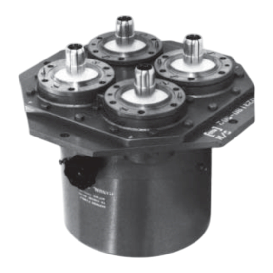
Page 3: General Description
General Description The Model 50000 Coaxial Switch provides re- Operable in any position and having a mini- mum of moving parts, the switch will routinely liable and fast switching of coaxial transmis- sion line systems. It is a motor driven rotary... -
Page 4: Theory Of Operation
Theory of Operation The Model 50000 Coaxial Switch is a rotary type Simultaneously, an auxiliary switch is activiated to switch having an aluminum RF cavity common to all interrupt the motor circuit. Any inertia of the drive ports. The rotor assembly contains two inner con- is absorbed by slippage of the clutch mechanism. -
Page 5: Fig. 1 Outline Drapwing
MS3108B jack sup- sitions to be sure rotor moves freely and reaches plied with each switch. Refer to Figure 2 for proper the positive stops. connections. • • • • Dielectric Communications 22 Tower Road Raymond, ME 04071 (207) 655-4555 (866) DIELECTRIC... -
Page 6: 5.0 Operation
- regardless of whether switch motor is used or not. Manual Control 5.0 Operation The 1 5/8”, 3 1/8” and 4 1/16” Model 50000 CAUTION switches will change positions in approximately two seconds upon command to the control relay. The 6 Remove RF power prior to the application 1/8”... -
Page 7: Maintenance And Repairs
Maintenance and Repairs The Model 50000 Switch requires no periodic switch inspected for loose electrical connections maintenance. However, after the initial installation and/or auxiliary switch hardware. is complete, the cover should be removed and the WARNING Removal of the cover may expose live electrical terminals (240V AC maximum). -
Page 8: Fig. 2 Schematic Diagram
• • • • Dielectric Communications 22 Tower Road Raymond, ME 04071 (207) 655-4555 (866) DIELECTRIC... - Page 9 Figure 2B. Schematic Diagram Model 50000 6 1/8” Coaxial Switch with 12/24 VDC control • • • • Dielectric Communications 22 Tower Road Raymond, ME 04071 (207) 655-4555 (866) DIELECTRIC...
- Page 10 Figure 2C. Schematic Diagram Model 50000 6 1/8” Coaxial Switch with 115 VAC control • • • • Dielectric Communications 22 Tower Road Raymond, ME 04071 (207) 655-4555 (866) DIELECTRIC...
-
Page 11: Replacement Parts
Aux. Micro-switch 0004374004 S3, S4 Plug 0019991003 Jack 0019720001 Cable Clamp 0023561001 Harness Assy, 0044586501 (incl. S1, S2, S3, S4, P1 and Relay Socket) • • • • Dielectric Communications 22 Tower Road Raymond, ME 04071 (207) 655-4555 (866) DIELECTRIC... -
Page 12: Ancillary Equipment
Type N-F C-14397-503 3 1/8” EIA-M 4 1/16” EIA-F *All components are copper; similar items having aluminum outer conductors are available. Contact Dielectric Communications for a complete line of coaxial and waveguide transmission lines and components. • • •... - Page 13 • • • • Dielectric Communications 22 Tower Road Raymond, ME 04071 (207) 655-4555 (866) DIELECTRIC...
Need help?
Do you have a question about the 50000 and is the answer not in the manual?
Questions and answers