
Summary of Contents for TIMM EKX-4
- Page 1 EKX-4 ROUNDING ONTROL EVICE PERATING NSTRUCTIONS NGLISH Timm Technology GmbH | Senefelder-Ring 45 | 21465 Reinbek | GERMANY...
- Page 2 If the cable lead-in and the cable glands are not properly fitted, IP 65 as minimum degree of protection will not be ensured. The Grounding Control Device EKX-4 is certified according to EN 61508:2010 to SIL 2 for use in safety-related systems. The safety characteristics for functional...
-
Page 3: Table Of Contents
Grounding Control Device EKX-4 | Operating Instructions Table of Contents Functional Principle ..............................3 Installation | Mounting ..............................5 Commissioning and Configuration ........................7 3.1. Setting configuration switch S4 | Object to be grounded ..........7 3.2. Checking the cable capacitance ......................9 3.3. -
Page 4: Functional Principle
Grounding Control Device EKX-4 | Operating Instructions 1. Functional Principle The Grounding Control Device type EKX-4 is intended to provide and monitor electrostatic grounding of objects such as road tank trucks, railway tank wagons, IBC, drums and other containers while filling with products that can form an explosive dust and gas atmosphere. - Page 5 Figure 1: Scheme of monitored electrostatic grounding of a road tank truck The safety function of the grounding control device EKX-4 is to switch off the safety relay contacts when the maximum permissible limit for the impedance of a connected object and the earthing connection is exceeded, thereby interrupting a filling or discharging process (no release).
-
Page 6: Installation | Mounting
Grounding Control Device EKX-4 | Operating Instructions 2. Installation | Mounting Install the grounding control device vertically with the cable glands pointing downwards. An appropriate mounting must be provided by the executor of construction work for this purpose. For hole distances see dimensional drawing (section 8.2, figure... - Page 7 Grounding Control Device EKX-4 | Operating Instructions To integrate the grounding control device EKX-4 into a safety-related system, the following safety-relevant interfaces are provided: Connecting terminals 1-2 (contact release output K1) und 3-4 (contact release output K2) The Release Contact Outputs (K1, K2) are duplicated, mechanically linked, redundant by serial relays each and continuously monitored by return signal.
-
Page 8: Commissioning And Configuration
Grounding Control Device EKX-4 | Operating Instructions 3. Commissioning and Configuration Check all electrical connections carefully before first switching-on power supply. For the electronic release output T1, only connections to intrinsically safe circuits with allowed limit values are permitted. During commissioning, it is recommended to check the safety function to ensure the expected behavior of the control outputs. - Page 9 Grounding Control Device EKX-4 | Operating Instructions At the configuration for grounding road tank trucks (#1) the object recognition function is activated with upper and lower limit. At the configuration for grounding railway tank wagons (#2) and at the configuration for grounding of road tank trucks AND railway tank wagons (#3), the evaluation of the lower limit of the object recognition is deactivated.
-
Page 10: Checking The Cable Capacitance
Grounding Control Device EKX-4 | Operating Instructions 3.2. Checking the cable capacitance The capacitance of the grounding cable depends on the type of installation. A check should be done to assess whether the capacitance of the grounding cable is in the permissible range for the cable compensation function being performed correctly. -
Page 11: Operation Of Grounding Control Device
Grounding Control Device EKX-4 | Operating Instructions 4. Operation of Grounding Control Device 4.1. Status (Full display) The status display is situated at the front of the device. It is read as a large display. Status Display Operating State Meaning... -
Page 12: Operational Use | Grounding
Grounding Control Device EKX-4 | Operating Instructions 4.2. Operational use | Grounding The following operation sequence must be followed: Ground first - then connect hoses or insert filling arm! Step 0: Grounding Control Device ready for use Full display orange pulsating (this indicates readiness when cable compensation function... -
Page 13: Optional Settings
Grounding Control Device EKX-4 | Operating Instructions 5. Optional Settings Note: With the configuration (section 3) and the preset limit values of the object recognition, the grounding control device is fully operational. However, in exceptional cases an alternative setting or cause analysis might become necessary, e.g. -
Page 14: Analyzing The Upper Limit Of Object Recognition
Grounding Control Device EKX-4 | Operating Instructions 5.2.1. Analyzing the upper limit of object recognition The grounding clamp must be connected to the object to be grounded. Step 1: Press button S1 briefly. Step 2: LED D1 illuminates orange. It represents the center of the measured value display (measured value is equal to current limit value). -
Page 15: Analyzing The Lower Limit Of Object Recognition
Grounding Control Device EKX-4 | Operating Instructions 5.2.2. Analyzing the lower limit of object recognition The grounding clamp must be connected to the object to be grounded. Step 1: Press button S2 briefly. Step 2: LED D4 illuminates orange. It represents the center of the measured value display (measured value is equal to current limit value). -
Page 16: Display The Object Impedance Type | Phase Angle
Grounding Control Device EKX-4 | Operating Instructions 5.2.3. Display the object impedance type | phase angle The grounding clamp must be connected to the object to be grounded. Step 1: Press button S3 briefly. Step 2: The display is realized with orange LEDs. LED D1 is the center of the measured value display (phase angle 45°). -
Page 17: Display The Cable Capacitance
Grounding Control Device EKX-4 | Operating Instructions 5.2.4. Display the cable capacitance The grounding clamp must not be connected to the object to be grounded and the cable compensation function must be activated (configuration switch S4.3 set to ON). The grounding control device is in operational state ‘Activated Cable Compensation / Ready for Operation‘... -
Page 18: Display The Interfering Voltage Level In The Grounding Circuit
Grounding Control Device EKX-4 | Operating Instructions 5.2.5. Display the interfering voltage level in the grounding circuit Potential equalization has to exist in the complete course of the erection of the intrinsically safe grounding circuit. It must be ensured that there are no interfering voltages which might lead to electro-magnetic influences or to unregulated stray currents. -
Page 19: Adjusting The Upper Limit Value Of Object Recognition
Grounding Control Device EKX-4 | Operating Instructions 5.3.1. Adjusting the upper limit value of object recognition Brief instruction: Press button S1 long (about 3 s) to switch display to setting mode 2. Press button S1 briefly to increase upper limit value by one step 3. -
Page 20: Adjusting The Limit Value For Interfering Voltage Supervision
Grounding Control Device EKX-4 | Operating Instructions Precise Explanation: To set the lower limit of object recognition, button S2 has to be pressed (about 3 seconds) until the display changes to setting mode. Thus, LED D4 flashes orange and is the center of the setting range. The limit can be moved by +4 to -4 steps around this point. -
Page 21: Reset The Limit Value Adjustment
Grounding Control Device EKX-4 | Operating Instructions Pressing button S3 briefly exits the setting mode and switches to the measured value display. The setting is stored permanently now. Pressing button S3 again switches to the main status display. 5.3.4. Reset the limit value adjustment... -
Page 22: Error Codes (Detailed Display)
Grounding Control Device EKX-4 | Operating Instructions 5.4. Error codes (Detailed display) The automatic diagnosis system indicates error states at the detailed display. To read the detailed display, the device housing has to be opened. Moreover, the indications of the full display as described in section 4.1... -
Page 23: Maintenance
6.1. Accessories and spare parts The Grounding Control Device EKX-4 has a variety of rugged, UV and oil resistant straight and coiled grounding cables in various designs and lengths, with or without a cable reel. - Page 24 Grounding Control Device EKX-4 | Operating Instructions The following items are available as replacement parts for the EKX-4 that can be exchanged by the customers: Operating board with measuring module (item number: LPB11-352 (when ordering, please specify whether intended for EKX-4 or EKX-4 2-pole)
-
Page 25: Periodical Function Test (Proof-Test)
Grounding Control Device EKX-4 | Operating Instructions 6.2. Periodical function test (Proof-test) The periodical function test conduces to check the safety function of the device. The functionality must be checked at appropriate intervals and must not exceed an interval of 5 years. -
Page 26: Return And Disposal
(so-called B2B devices). For these devices, identified by a type plate with the brand name TIMM, a serial number and date of delivery, H. Timm Elektronik GmbH handles the proper disposal of waste as long as such devices were introduced to the market after August 12th 2005. -
Page 27: Technical Annex
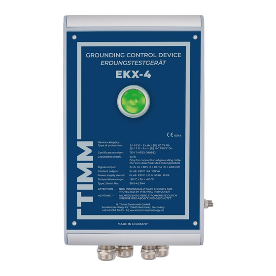
Grounding Control Device EKX-4 | Operating Instructions 8. Technical Annex 8.1. Technical specifications Device category − type of protection: II 2 G – Ex eb q [ib] IIC T4 Gb II 2 D – Ex tb [ib] IIIC T80°C Db EC Type Examination: TÜV 11 ATEX 080882... -
Page 28: Safety Characteristics For Functional Safety
Grounding Control Device EKX-4 | Operating Instructions 8.2. Safety characteristics for functional safety The following table shows the relevant parameters and values for evaluating the functional safety of the device. Parameters and values acc. to IEC 61508 System λ λ... -
Page 29: Drawings
Grounding Control Device EKX-4 | Operating Instructions 8.3. Drawings Drawing 1: Connection diagram info@timm-technology.de 04.01.2023 | V 1.9 | EN www.timm-technology.com 28 | 41... - Page 30 Grounding Control Device EKX-4 | Operating Instructions Drawing 2: Dimensional drawing info@timm-technology.de 04.01.2023 | V 1.9 | EN www.timm-technology.com 29 | 41...
- Page 31 Grounding Control Device EKX-4 | Operating Instructions Screw to open the housing (4 screws in total, one in each corner) Switch S4 Buttons S1 bis S3 LEDs D1 to D6 Flat plug Outer earth conductor terminal (PA) Terminal cover Drawing 3: Connection diagram info@timm-technology.de...
-
Page 32: Ec Type Examination Certificate
Grounding Control Device EKX-4 | Operating Instructions 8.4. EC Type Examination Certificate info@timm-technology.de 04.01.2023 | V 1.9 | EN www.timm-technology.com 31 | 41... - Page 33 Grounding Control Device EKX-4 | Operating Instructions info@timm-technology.de 04.01.2023 | V 1.9 | EN www.timm-technology.com 32 | 41...
- Page 34 Grounding Control Device EKX-4 | Operating Instructions info@timm-technology.de 04.01.2023 | V 1.9 | EN www.timm-technology.com 33 | 41...
-
Page 35: Certificate Of Functional Safety
Grounding Control Device EKX-4 | Operating Instructions 8.5. Certificate of functional safety info@timm-technology.de 04.01.2023 | V 1.9 | EN www.timm-technology.com 34 | 41... - Page 36 Grounding Control Device EKX-4 | Operating Instructions info@timm-technology.de 04.01.2023 | V 1.9 | EN www.timm-technology.com 35 | 41...
- Page 37 Grounding Control Device EKX-4 | Operating Instructions info@timm-technology.de 04.01.2023 | V 1.9 | EN www.timm-technology.com 36 | 41...
- Page 38 Grounding Control Device EKX-4 | Operating Instructions info@timm-technology.de 04.01.2023 | V 1.9 | EN www.timm-technology.com 37 | 41...
-
Page 39: Eu Declaration Of Conformity
Grounding Control Device EKX-4 | Operating Instructions 8.6. EU Declaration of Conformity info@timm-technology.de 04.01.2023 | V 1.9 | EN www.timm-technology.com 38 | 41... - Page 40 Grounding Control Device EKX-4 | Operating Instructions info@timm-technology.de 04.01.2023 | V 1.9 | EN www.timm-technology.com 39 | 41...
- Page 41 Grounding Control Device EKX-4 | Operating Instructions info@timm-technology.de 04.01.2023 | V 1.9 | EN www.timm-technology.com 40 | 41...
- Page 42 Grounding Control Device EKX-4 | Operating Instructions info@timm-technology.de 04.01.2023 | V 1.9 | EN www.timm-technology.com 41 | 41...
Need help?
Do you have a question about the EKX-4 and is the answer not in the manual?
Questions and answers