Table of Contents
Advertisement
Quick Links
BOILER + FAN-COIL
Installation & Operation
Manual
Models >
ANSI Z21.13 | CSA 4.9
Gas-fired low-pressure steam and hot water boilers
UL 1995 | CSA C22.2 No. 236
Heating and Cooling Equipment
IMPORTANT:
•
Be sure to read these instructions and fully understand prior to
installing this product.
After installation, store instructions near product for future reference.
•
This product must be installed and serviced by a properly trained &
•
licensed professional heating contractor – FAILURE TO COMPLY
WILL VOID ALL PRODUCT WARRANTY
Instructions are part of technical document package that on completion
•
of installation must be handed over to the Owner or Operator of the
heating system. Explain to the Owner or Operator how to correctly use
the heating system, following the requirements of these Installation &
Operation Instructions and local codes. Be sure that they are familiar
with all heating system equipment as well as safety
precautions/requirements, shut-down procedure(s) and the need for
professional service annually before the heating season begins.
CAUTION:
•
After installation is complete it is the responsibility of the Owner or
Operator to ensure vent terminal(s) is cleared from snow, ice and/or
other debris.
syncFURNACE – User Information Manual / Installation & Operation Instructions – Rev 14
H
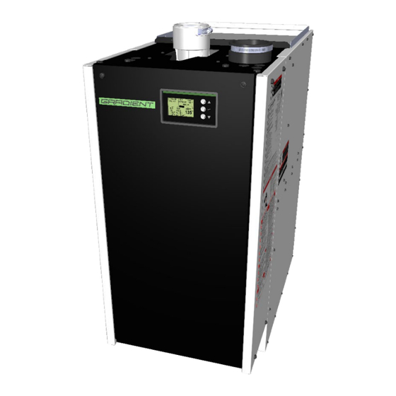
Combination Gas-Fired Condensing Boiler / Central Air Fan-coil Unit
mCH-100 , mCH-150 , mCH-200
www.gradientthermal.com
(Pending)
Pg. 1 of 84
(Pending)
Advertisement
Table of Contents

Summary of Contents for Gradient syncFURNACE mCH-100
- Page 1 Combination Gas-Fired Condensing Boiler / Central Air Fan-coil Unit BOILER + FAN-COIL Installation & Operation Manual mCH-100 , mCH-150 , mCH-200 Models > ANSI Z21.13 | CSA 4.9 Gas-fired low-pressure steam and hot water boilers UL 1995 | CSA C22.2 No. 236 Heating and Cooling Equipment IMPORTANT: •...
- Page 2 syncFURNACE – User Information Manual / Installation & Operation Instructions – Rev 14 Pg. 2 of 84...
-
Page 3: Table Of Contents
Index 1. Guideline to Symbols > ......................4 2. French Translations for Quoted Instructions and Markings (Canada Only) > ......4 3. General and Safety Instructions > ..................5 4. Included in Packaging > ......................5 5. Regulatory & General Installation Requirements > ..............6 6. -
Page 4: Guideline To Symbols
Testing Combustion: ........................63 10. Maintenance & Service > ....................65 Burner Cleaning [At Minimum, Perform Annually]: ................. 65 Clean Combustion Chamber [At Minimum, Perform Annually]: ............66 Check and Clean Condensation Line and Trap [At Minimum, Perform Semi-Annually]:......66 Flue Gas Vent &... -
Page 5: General And Safety Instructions
2. These instructions must be kept at installation site. Additional copies are available - on request - from Gradient Thermal Inc. 3. Installation, Start-up & Service must be performed with due care and attention and must only be performed by competent, qualified, licensed and trained heating contractor(s). -
Page 6: Regulatory & General Installation Requirements
5. REGULATORY & GENERAL INSTALLATION REQUIREMENTS > 1. syncFURNACE must be installed in accordance with the instructions and details outlined in this manual. Failure to comply will result in product warranty to be null and void. 2. The installation of this product must conform to the requirements of the local authority having jurisdiction or, in the absence of such requirements, to the National Fuel Gas Code, ANSI Z223.1/NFPA 54, and/or Natural Gas and Propane Installation Code, CAN/CSA B149.1. -
Page 7: Product Information & Specifications
15. Suggested list of codes and standards for the United States and Canada - a. General Installation: - Installation of Air Conditioning and Ventilation Systems NFPA 91 (latest edition). b. Duct Systems: i. Sheet Metal and Air Conditioning Contractors National Association (SMACNA) ii. - Page 8 IN THE STATE OF MASSACHUSETTS ONLY (a) For all side-wall vented gas fueled equipment installed in every dwelling, building or structure used in whole or in part for residential purposes, including those owned or operated by the Commonwealth and where the side-wall exhaust vent termination is less than seven (7) feet (2.14m) above finished grade in the area of the venting, including but not limited to decks and porches, the following requirements shall be satisfied: 1.
-
Page 9: Specifications
SPECIFICATIONS: Low Velocity / Normal Static Duct High Velocity / High Static Duct Physical Weight 38 x 37 38 x 37 38 x 37 38 x 37 38 x 37 38 x 37 38 x 37 38 x 37 Dimensions [H x L x W] x 17.5 x 17.5 x 21... -
Page 10: Model Number Identification
MODEL NUMBER IDENTIFICATION: mCH-100-N-14L-P-N-1 Hydronic Configuration 1 = 1 Set, Supply / Retu rn Model Name 2 = 2 Sets, Supply / Return 3 = 3 Sets, Supply / Return mCH = Integrated, Modul at ing Gas-Fired Condensin g Boi ler & Hydroni c Fan Coil Uni t Controller N = No Duct Zoning Versi on Boiler Max Input Capacity... -
Page 11: Dimensions And Connection Descriptions
7. DIMENSIONS AND CONNECTION DESCRIPTIONS > mCH-100 DIMENSIONS Location Xref Location Yref Thread ↔ ↕ Pipe Connection Specification Inch Inch A - INTERNAL PRV TO DRAIN 3/4" NPT FEMALE 1.63 4.50 B - CONDENSATE TO DRAIN 3/4" NPT FEMALE 1.63 6.54 C - ZONE 1 RETURN [IN] 3/4"... - Page 12 mCH-150 / 200 – 10L / 14L mCH-150 / 200 – 06H / 10H DIMENSIONS DIMENSIONS Location Location Thread ↔ ↕ Pipe Connection Xref Yref Specification Inch Inch A - INTERNAL PRV TO DRAIN 3/4" NPT FEMALE 1.81 6.17 B - CONDENSATE TO DRAIN 3/4"...
- Page 13 mCH-150 / 200 – 18L mCH-150 / 200 – 15H DIMENSIONS DIMENSIONS Location Location Thread ↔ ↕ Pipe Connection Xref Yref Specification Inch Inch A - INTERNAL PRV TO DRAIN 3/4" NPT FEMALE 1.81 6.17 B - CONDENSATE TO DRAIN 3/4"...
- Page 14 mCH-150 / 200 – 22L mCH-150 / 200 – 18H DIMENSIONS DIMENSIONS Location Location Thread ↔ ↕ Pipe Connection Xref Yref Specification Inch Inch A - INTERNAL PRV TO DRAIN 3/4" NPT FEMALE 1.81 6.17 B - CONDENSATE TO DRAIN 3/4"...
-
Page 15: Installation
8. INSTALLATION > MINIMUM CLEARANCES: Front Back Sides Bottom Vent Pipe Clearance Requiements Inch Inch Inch Inch Inch Inch Minimum Recommended for Service 25.4 Note: 1. It is highly suggested that Recommended for Service minimum clearance requirements are maintained to ensure straight forward access for future product service / maintenance. 2. -
Page 16: General Venting
GENERAL VENTING: syncFURNACE has an internal “Category IV” high-efficient condensing boiler that utilizes a modulating gas power burner. This product requires a “Special Venting System” designed for pressurized venting. syncFURNACE is suitable for use for sidewall (horizontal) and vertical venting using field supplied venting materials. - Page 17 DO NOT locate syncFURNACE install operate CAUTION in areas where high levels of syncFURNACE during dust or humidity are present construction periods involving CAUTION drywall or heavy dust of any kind. Can cause heavy suiting of If syncFURNACE has been burner heat exchanger...
-
Page 18: Removal Of Existing Boilers
REMOVAL OF EXISTING BOILERS: 1. When removing an existing boiler from a common venting system, it is most likely the common venting system will be too large for proper venting of the remaining appliances connected to it. It may need to be re-sized. When re-sizing any portion of the common venting system, it should be re-sized to approach the minimum size as determined using the appropriate tables;... -
Page 19: Acceptable Vent Configurations
ACCEPTABLE VENT CONFIGURATIONS: 1. Direct Vent, Two-pipe systems consisting of the following termination types; a. Horizontal air intake and exhaust vent pipes b. Vertical air intake and exhaust vent pipes c. Horizontal air intake and vertical exhaust pipes Installer must follow the instructions of this manual and install in accordance with the National Fuel Gas Code, ANSI Z223.1 (U.S.) or CSA B149.1 (Canada) and local codes. - Page 20 Max Equivalent Lengths Max Equivalent Maximum Number Model Vent Size Fuel Length of Elbows 2" [60mm] Natural Gas 75 feet [22.86m] 2" [60mm] Propane 35 feet [10.67m] m CH-100 3" [80mm] Natural Gas 125 feet [38.1m] 3" [80mm] Propane 50 feet [15.24m] 3"...
- Page 21 Notes: 1. syncFURNACE is supplied with 3” Flue Gas and Combustion Air vent connections. If reducing to 2”, make transition as soon as possible. 2. Minimum acceptable equivalent vent length is 5 feet (1.53m) for 2” diameter materials and 8 feet (2.44m) for 3”...
-
Page 22: Room Dependent Combustion Air Supply
Only use solvents & cements in well vented areas. Do not use near open flame or open fire. Only use the appropriate solvent & cement for the venting CAUTION material being installed. SOLVENTS & CEMENTS ARE FLAMMABLE LIQUIDS AND MUST BE KEPT AWAY FROM ALL SOURCES OF IGNITION –... -
Page 23: Connecting Vent Pipe To Syncfurnace
6. WHEN USING STAINLESS STEEL AL-29-4C venting products, an adapter is required to adapt from syncFURNACE to Stainless Steel AL-29-4C – This adapter can be ordered from Gradient Thermal Inc. – GTI Part No. 110142 In Canada the first three (3) feet (.92m) of vent pipe must be readily NOTE accessible for inspection. -
Page 24: Venting Termination Options
VENTING TERMINATION OPTIONS: Approved Vent Termination Kits Standards MFG Part Canada Vertical & Horizontal - IPEX ANSI/ASTM IPEX CPVC Concentric Kit - 3" 197009 ULC-S 636 F441 Vertical Only - Innoflue Chimney Cover SS W/PPs - 3" ISCM03 ULC-S 636 UL-1738 2"... - Page 25 12. At termination point, install vent screens into the last opening for both the Flue Gas Outlet and Combustion Air Inlet fittings. 13. For sidewall terminations - if additional rigidity is required, secure Combustion Air Inlet and Flue Gas Outlet piping to external wall. 14.
-
Page 26: Venting Termination Clearances
VENTING TERMINATION CLEARANCES: For installations in Canada, vent terminations must follow the requirements of Local and National Codes – CAN/CSA B149.1 or 2. NOTE For installations in the United States of America, vent terminations must follow the requirements of Local and National Codes – ANSI Z223.1 or NFPA 54 In Canada and the USA the Combustion Air Inlet termination MUST NOT be –... -
Page 27: Mandatory Venting Pre-Fire Procedure
MANDATORY VENTING PRE-FIRE PROCEDURE: Do not apply power to syncFURNACE prior to performing the mandatory WARNING venting pre-fire procedure for plastic venting. This procedure is required for IPEX venting materials that are assembled using solvents and cements. Once the venting system has been fully assembled follow these steps: 1. -
Page 28: Condensation Trap
CONDENSATION TRAP: To achieve maximum operating efficiency, flue gases inside the heat exchanger and chimney will condense during burner operation. It is critical that the venting system be installed in accordance with the requirements of this manual so that condensate properly drains back into the heat exchanger and out the side discharge. - Page 29 & heat exchanger will need to be inspected and cleaned. The internal refractory, gaskets, flame sensor & direct spark igniter may need to be replaced with Certified Replacement Parts from Gradient Thermal Inc. Failure to properly inspect and repair will result in dangerous boiler operation resulting in property damage, fire or loss of life.
-
Page 30: Gas Line Connection -- Mch-100 Model
GAS LINE CONNECTION -- MCH-100 MODEL: Gas-line sizing and the connection to syncFURNACE must be made in accordance to current edition of codes CAN/CSA B149.1 or .2, or National Fuel Gas Code ANSI Z223.1/NFPA 54, as well as local codes where applicable. -
Page 31: Gas Line Connection -- Mch-150 / 200 Model
GAS LINE CONNECTION -- MCH-150 / 200 MODEL: Gas-line sizing and the connection to syncFURNACE must be made in accordance to current edition of codes CAN/CSA B149.1 or .2, or National Fuel Gas Code ANSI Z223.1/NFPA 54, as well as local codes where applicable. -
Page 32: Plumbing Syncfurnace
15 psi (1 bar) when in stanby mode. All piping MUST be pressure tested. For both new & retro-fit applications, thoroughly flush external hydronic piping prior to connecting and filling syncFURNACE. Only use Gradient Approved cleaners and WARNING corrosion inhibitors. - Page 33 DO NOT install an isolation valve in-line with the PRV to Drain line. The discharge pipe for the pressure relief valve must be orientated to prevent scalding of attendants. Pipe pressure relief valve discharge pipe close to the floor – follow the requirements of the local and national codes.
- Page 34 HVAC duct system. The fan-coil has been pre-engineered by Gradient to use lower supply water temperature (same as in-floor radiant heating applications), than a conventional fan-coil, to provide warm-air space heating. This increases boiler operating efficiency. Zone 2 supply water setpoints are determined using a reset curve and outdoor temperature readings (when outdoor sensor is installed).
- Page 35 syncFURNACE version mCH-100-3 / mCH-150-3: syncFURNACE is available from factory in a 3-zone model. This model incorporates the same functionality as the 2-zone, but includes a second internal boiler pump to manage fluid circulation for Zone 3 heating loads. This allows the product to connect to a third heat emitter [Zone 3]. Zone 3 can connect with hydronic heating applications such as in-floor, fan-coil, baseboard radiator etc.
-
Page 36: Boiler Water Quality/Treatment Requirements (Closed-Loop Heating Fluid Only)
25 ppm chloride b. 25 ppm sulfate 6. Boiler water must be treated with Gradient Approved corrosion inhibitor (see below table). At all times, inhibitor amount must be greater than 0.5% concentration of total water volume. The inhibitor concentration must be monitored (and corrected if necessary) within the first month of product operation and then on an annual basis. -
Page 37: Filling The System
FILLING THE SYSTEM: Prior to connecting this product to the external hydronic system, ensure that entire external hydronic system has been flushed to eliminate sediment, flux, solder, scale, construction debris, dust, sand, dirt or other impurities that are harmful to the system and boiler during operation. This product is designed for use solely in pressurized closed loop heating systems operating with a minimum pressure of 15 psi (1 bar) at the boiler gauge during stand-by. -
Page 38: Connecting Control (Low-Voltage) Wiring
CONNECTING CONTROL (LOW-VOLTAGE) WIRING: Ensure the main supply power to syncFURNACE is turned OFF whenever the control wiring panel is removed. Under any circumstance is there ever a need to apply an external power source to any of the low-voltage connection terminals. - Page 39 Low Voltage Terminals: Low Voltage Wire Terminals Terminal Description Neutral for Control 24Vac - Wire to thermostat for power Control 24Vac Hot - Wire to thermostat, power supply for W,R,G,Y1,Y2 demands Wire to thermostat - When energized provides signal to syncFURANCE for Warm-air heating demand Wire to thermostat - When energized provides signal to syncFURANCE for Fan-circulation demand...
-
Page 40: Connecting Main Power (115Vac) Wiring
10°F below the switch set-point point. The other limit switch is located in the boiler jacket and is not resettable. If this switch opens, contact Gradient Thermal Inc. for service and support. These switches are included in the product to prevent excessive overheating. DO NOT TAMPER WITH THE WIRING OR POSITION OF THESE SWITCHES. - Page 41 Electric Shock Hazard. Can cause injury or death. Before attempting to perform any WARNING service or maintenance, turn the electrical power to unit OFF at externally installed service switch. CAUTION FOR ALL FIELD WIRING: USE ONLY COPPER CONDUCTOR SUPPLY WIRE SUITABLE FOR 105°C (221°F) syncFURNACE –...
-
Page 42: Connecting External Zone Pump(S) (115Vac) Wiring
CONNECTING EXTERNAL ZONE PUMP(S) (115VAC) WIRING: The Gradient controller includes internal 115Vac pump relays designed to operate a combination of internal and external zone pumps. mCH 2-zone models have capability to operate up to 3 external pumps plumbed as secondary pumps on a primary / secondary piping arrangement on Zone 1, while mCH 3-zone models have capability to operate up to 2 external pumps when plumbed as secondary pumps on a primary / secondary piping arrangement on Zone 3. - Page 43 syncFURNACE – User Information Manual / Installation & Operation Instructions – Rev 14 Pg. 43 of 84...
- Page 44 syncFURNACE – User Information Manual / Installation & Operation Instructions – Rev 14 Pg. 44 of 84...
-
Page 45: Fan-Coil Installation
FAN-COIL INSTALLATION: General Requirements: 1. syncFURNACE Hydronic Fan-coil installation must conform to local building codes. 2. syncFURNACE can only be installed in up-flow installation types. 3. It is highly recommended to install so that the side panels are accessible after installation for future maintenance and service. - Page 46 Return Air Duct Options: RECOMMENDED FILTER SLOT SIZE (508mm x 635mm x 25.4mm) 20" x 25" x 1" Cleana ble Filter Slot RETURN AIR CUT-OUT (EITHE R SIDE ) 18" (457mm) RETURN AIR PLENUM 2" 23" (584mm) (51mm) 1 ½” 1"...
- Page 47 When return air is drawn from a room, a negative pressure is created in the room. If a fossil fuel appliance is operating in a room with negative pressure, flue products can be pulled back down the vent pipe and in the room. This reverse flow of the flue gas may result in incomplete combustion and the formation of carbon monoxide gas.
-
Page 48: Control Setup
CONTROL SETUP: syncFURNACE has an advanced internal controller that incorporates Gradient’s Next Generation Multi-zone Control Technolgoy™ and is capable of controlling up to 4 hydronic zones operating at different supply temperature setpoints through a priority logic. It is fully customizable and designed to allow user adjustment according to type of hydronic heat emitter(s) connected to the product. - Page 49 Setpoint Differential Default Settings 125°F 6°F Cool 2 Heating Fan Circ Fan Cool 1 Fan Climate Gradient Fan-coil Blower - Default Speed Speed Speed Profile Settings Speed 100% syncFURNACE – User Information Manual / Installation & Operation Instructions – Rev 14...
- Page 50 BUILT IN PRIORITY AND LOAD SHARE MAX LOGIC: syncFURNACE has built-in priority and load share max logic to allow operation of multiple zone heating demands while preventing higher boiler supply temperature from being supplied to low temperature applications. The priority is configured so that any zones setup as DHW emitter type are given all burner input until either the demand is satisfied or the burner input reaches a level that it can sustain turning on a lower priority demand –...
- Page 51 NAVIGATING THE SYNCFURNACE CONTROLLER: To cycle through the different main boiler information screens and access to the syncFURNACE SETUP MENU is achieved by using the three buttons (and combination thereof) located to the right of the control screen. (UP) button is used to scroll up through the main boiler information screens, scroll up in syncFURNACE SETUP MENU screens and increase...
-
Page 52: Zone Setup
SYNCFURNACE SETUP MENU: syncFURNACE SETUP MENU is used for configuration of zone applications, adjusting the design values, burner combustion testing options, commissioning options and remote monitoring setup of syncFURNACE. To access the SETUP MENU push and hold SET for 10 seconds. Use the UP or DOWN buttons to scroll through the various settings. - Page 53 DHW Emitter Type with Sensor as Trigger ZONE 1 SETUP Emitter EMITTER: - This setting allows users to select different emitter types based on the actual emitter TRIGGER: SENSOR type / application that this zone is piped with. SUPPLY TARGET: °F DHW TANK SETUP (DHW, OTHER FAN COIL, IN-FLOOR, IN-JOIST, RADIATOR) Default: DHW...
- Page 54 - As the fan-coil is an integral part of syncFURNACE, Zone 2 is always configured (and 3) ZONE 3 cannot be changed) as GRAD FAN-COIL. 4) ZONE 4 5) RESTORE DEFAULTS GRADIENT FAN COIL Emitter Type ZONE 2 SETUP Emitter EMITTER: GRAD FAN COIL - For syncFURNACE, Zone 2 emitter is always GRAD FAN COIL type.
- Page 55 ZONE SETUP Zone 3 (and Zone 4) 1) ZONE 1 - Allows identification of the emitter type and system setpoints associated with Zone 3. 2) ZONE 2 - Default setup is IN-FLOOR emitter type. 3) ZONE 3 4) ZONE 4 NOTE: Zone 4 has the exact same default (factory) setup as Zone 4.
- Page 56 RADIATOR Emitter Type SUPPLY MAX = Maximum boiler supply temperature on the coldest day – used in outdoor reset calculation. (175°F to 80°F) Default: 175°F SUPPLY MIN = Minimum boiler supply temperature, as outdoor temperature approaches WWSD, boiler supply will be reduced closer to this setting.
- Page 57 BURNER SETUP: SETUP MENU Burner Setup 1) ZONE SETUP - Used to force burner to operate at MAXIMUM, MINIMUM or IGNITION burner input rate to 2) BURNER SETUP perform gas valve calibration and/or combustion analysis of burner system. 3) COMMISSIONING 4) STATISTICS 5) REMOTE MONITORING Burner Setup...
-
Page 58: Commissioning
9. COMMISSIONING > Before placing the product into operation ensure; CHECK 1. Venting system is completely assembled and seal tested. Ensure venting system meets the requirements of the Venting Installation sections in this manual. Ensure the pre-fire venting procedure has been completed. Confirm that venting system is not shared with any other gas burner appliance in the home. -
Page 59: Testing Gas Inlet Pressure
Check the rating plate on syncFURNACE to ensure it is configured for the fuel type you are using. The gas valve is factory supplied to use NATURAL-GAS fuel. A conversion kit supplied by Gradient Thermal Inc. is required to convert to use propane fuel – part no. 110201. - Page 60 Testing Gas Inlet Pressure (Con’t): For your safety read before operating - It is the responsibility of the installing contractor to ensure that all controls are operating properly when the installation is completed. Set temperature control to the WARNING desired temperature and cycle the product several times to ensure proper operation of product.
- Page 61 syncFURNACE – User Information Manual / Installation & Operation Instructions – Rev 14 Pg. 61 of 84...
- Page 62 Testing Gas Inlet Pressure (Con’t): A CO Measurement must be taken before and after working on the boiler to eliminate risks to health and to guarantee the performance of the system. Ensure CO reading is CAUTION less than 180 ppm @ MAX input. If CO is > 180 ppm follow the Combustion setting instructions to reduce reading.
-
Page 63: Testing Combustion
TESTING COMBUSTION: syncFURNACE has a pre-mix modulating gas burner combustion system. It uses a negative pressure gas- valve that is pre-set and calibrated at factory for optimized boiler performance. During a demand for heat, the syncFURNACE controller sets a target supply water temperature for the demand and modulates burner energy input (between Maximum and Minimum Input Rating) into the boiler to only provide the required energy so the actual water temperature equals the supply water temperature target. - Page 64 7. If values are within the range in the table turn-off heat demand, insert plug back into Combustion Analyzer Measurement Port and return syncFURNACE back to normal operating condition – ensure that “BURNER ORIDE” is set to “OFF”. There is no need to continue on to step 8. If combustion readings are outside the acceptable range continue to step 8.
-
Page 65: Maintenance & Service
10. MAINTENANCE & SERVICE > The building owner is responsible for keeping the Flue Gas Outlet and Combustion Air Inlet terminations free from snow, ice, or other potential blockages and for scheduling NOTE boiler maintenance and service as described in this section. FAILURE TO PROPERLY MAINTAIN THE BOILER MAY RESULT IN SERIOUS INJURY OR DEATH. -
Page 66: Clean Combustion Chamber [At Minimum, Perform Annually]
CLEAN COMBUSTION CHAMBER [AT MINIMUM, PERFORM ANNUALLY]: 1. With burner still removed, inspect internal surfaces of combustion chamber. 2. Vacuum inside combustion chamber using a vacuum with nylon brush and high-efficiency filter. 3. Inspect the condition of the insulation disc at the back of the combustion chamber. Cover it to protect it from being damaged or becoming wet during the cleaning process. -
Page 67: Flue Gas Vent & Air Intake Sealing [At Minimum, Perform Annually]
FLUE GAS VENT & AIR INTAKE SEALING [AT MINIMUM, PERFORM ANNUALLY]: 1. Using Flat-head screw driver, ensure worm-gear clamps are tight that connect the gas-valve air supply shroud to the combustion air supply tube. 2. Inspect the Combustion Air intake line, both inside the appliance and outside to ensure no leaks or worn parts are present. -
Page 68: Troubleshooting
Condensate Trap Pressure Switch – Undersized drain or partial or full trap blockage 2. Corrective action for limit switch – a. Vent Limit Switch – Contact Service/Repair Contractor & Gradient Thermal Inc. b. Boiler Supply Hi-Limit Switch – i. Check for pump(s) failure ii. - Page 69 iii. Clean trap and remove all blockages from heat exchanger outlet to floor drain iv. Test and visually inspect to ensure free flowing condensate to drain 3. If all safeties are closed and not receiving power, check controller to see if its applying power to the safety line / ignition module as per internal wire diagram.
- Page 70 1. Check boiler fill and ensure filling device is functioning properly and within safe operating characteristics - SEE filling device installation and operation manual. 2. Ensure all valves are open and heating fluid is able to enter and fill the system piping. 3.
-
Page 71: Appendix A: Internal Wiring Diagram Mch-100
APPENDIX A: INTERNAL WIRING DIAGRAM MCH-100 > syncFURNACE – User Information Manual / Installation & Operation Instructions – Rev 14 Pg. 71 of 84... -
Page 72: Appendix B: Internal Wiring Diagram Mch-150 / 200
APPENDIX B: INTERNAL WIRING DIAGRAM MCH-150 / 200 > syncFURNACE – Internal Wiring Diagram CAUTION! Label all wires pri or to di sconnection wh en servici ng c ontrols. Wiri ng errors can cause improper and dangerous operation. Verify proper operation aft er servicing. GREEN CHASSIS GND #1 MAIN POWER... -
Page 73: Appendix C: Sequence Of Events
APPENDIX C: SEQUENCE OF EVENTS > syncFURNACE – User Information Manual / Installation & Operation Instructions – Rev 14 Pg. 73 of 84... -
Page 74: Appendix D: Replacement Parts List
APPENDIX D: REPLACEMENT PARTS LIST > syncFURANCE Replacement Parts List - Shown Order Item No. Component Description Part No. HEAT EXCHANGER ASSY VERSION > 110148 mCH-100 HEAT EXCHANGER ASSY VERSION > 110143 mCH-150 HEAT EXCHANGER ASSY VERSION > 110997 mCH-200 PRES &... - Page 75 syncFURANCE Replacement Parts List - Shown Order Item No. Component Description Part No. WARM-AIR HEATING COIL 110054 FAN-COIL MANUAL AIR BLEEDER 110164 24Vac TRANSFORMER - 40va 110165 110166 BLOWER & MOTOR ASSY - mCH-100 BLOWER & MOTOR ASSY - mCH-150 110848 VENT SYSTEM PRESSURE SWITCH 110168...
-
Page 76: Appendix E: Handling Instructions For Refractory Cement Fibers (Rfc)
APPENDIX E: HANDLING INSTRUCTIONS FOR REFRACTORY CEMENT FIBERS (RFC) > Reduce the Risk of Exposure Precautions and Recommended Personal Protective Equipment Avoid contact with skin and eyes • Wear long-sleeved clothing, gloves and safety goggles or glasses. Avoid breathing in silica dust Wear a respirator with a N95-rated filter efficiency or better. -
Page 77: Appendix F: Annual Inspection & Maintenance Record
APPENDIX F: ANNUAL INSPECTION & MAINTENANCE RECORD > Required Inspection-points @ Installation Year 2 Year 3 Year 4 Year 5 Date: Date: Date: Date: Date: Inspect the general condition of the heating system & its components Test functions of all the demands wired into the product 3 C heck gas system for leaks 4 C heck plumbing system for leaks... - Page 78 Required Inspection-points Year 6 Year 7 Year 8 Year 9 Year 10 Date: Date: Date: Date: Date: Inspect the general condition of the heating system & its components Test functions of all the demands wired into the product 3 C heck gas system for leaks 4 C heck plumbing system for leaks Verify product chasis ground through continuity check with volt...
-
Page 79: Appendix G: Pressure Vessel And Internal Pump Specifications
APPENDIX G: PRESSURE VESSEL AND INTERNAL PUMP SPECIFICATIONS > PRESSURE VESSEL HEAD LOSS: Boiler Pressure Vessel Head Loss Curve 100 Model 200 Model 150 Model mCH-100: MINIMUM BOILER FLOW RATE = 2 GPM mCH-150: MINIMUM BOILER FLOW RATE = 4 GPM mCH-200: MINIMUM BOILER FLOW RATE = 6 GPM Flow Rate (GPM) -
Page 80: Appendix H: Air-Side Blower Setup Tables
APPENDIX H: AIR-SIDE BLOWER SETUP TABLES > syncFURNACE-100 syncFURNACE-150 & 200 10x8 Blower, 1/2 HP Motor 11x10 Blower, 1HP Motor CFM Output Static Pressure Blower RPM CFM Output Static Pressure Blower RPM 0.60 1050 0.60 1100 0.50 0.50 1050 0.40 0.40 1020 1400... -
Page 81: Appendix I: Low-Voltage External Wire Diagram
APPENDIX I: LOW-VOLTAGE EXTERNAL WIRE DIAGRAM > Note: See www.gradientthermal.com for additional application drawings specific to your application. syncFURNACE – Typical Control Wiring Diagram WARNING! Disconnect power before servicing this product. Ensure Main Power Supply is disconnected before accessing control wiring. Indirect Domestic Hot Water Tank ATTENTION! Débranchez l'alimentation avant d'intervenir Aquastat... -
Page 82: Appendix J: Example Humidifier Wiring Diagram
!! All Components are Field Supplied !! Typical Home Thermostat !! DO NOT APPLY EXTERNAL VOLTAGE TO ANY OF THESE WIRES !! Gradient Controller – TOP VIEW Rev: 01 syncFURNACE – User Information Manual / Installation & Operation Instructions – Rev 14 Pg. 82 of 84... -
Page 83: Appendix K: Low-Water Cut-Off Installation
DO NOT install an isolation valve between the product and the LWCO. Follow the installation & wiring instructions provided by the manufacturer of the LWCO. Consult Gradient Thermal Inc. for optional LWCO Kit that installs inside the syncFURNACE cabinet on top of the stainless steel heat exchanger. - Page 84 Disclaimer Gradient Thermal Inc. shall not be responsible for errors in its brochures or printed materials. Gradient Thermal Inc. reserves the right to alter its products at any time without notice, provided that alterations to products already on order shall not require material changes in specifications previously agreed upon by Gradient Thermal Inc.
Need help?
Do you have a question about the syncFURNACE mCH-100 and is the answer not in the manual?
Questions and answers