Table of Contents
Advertisement
Quick Links
Operating Instructions
for machine operator and maintenance staff
always keep by the machine
Translation of the original Operating Instructions
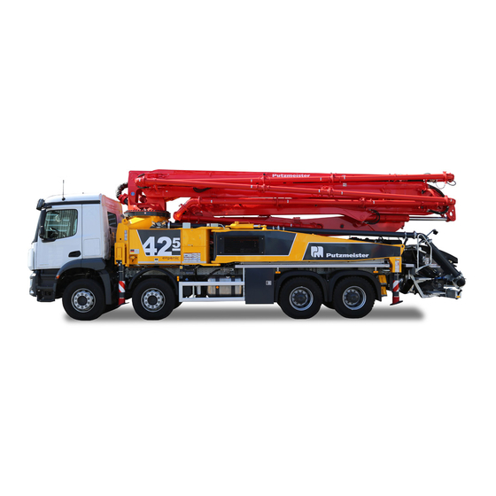
Truck–mounted
concrete pump
Machine no.
17−03−31
The paper on which this document is printed is 100% chlorine free
BSF 42–5.16 H
210109797
E Putzmeister Concrete Pumps GmbH 1994
Advertisement
Chapters
Table of Contents

Related Manuals for Putzmeister BSF 42-5.16 H


Summary of Contents for Putzmeister BSF 42-5.16 H
- Page 1 Translation of the original Operating Instructions Truck–mounted concrete pump BSF 42–5.16 H Machine no. 210109797 17−03−31 The paper on which this document is printed is 100% chlorine free E Putzmeister Concrete Pumps GmbH 1994...
- Page 2 Carrwood Road PMUK GB−Chesterfield +44−1246−26 00 77 www.putzmeister.co.uk Derbyshire S41 9QB Türkiye +90−282−735−1000 pm@putzmeister.com.tr Putzmeister Makine Sanayi ve Tic. A. G.O.Pa a Mah. Nam k Kemal Bulvar No: 6 +90−282−738−1001 www.putzmeister.com.tr 59500 Çerkezköy / TEK RDA Putzmeister America +1−262−886−3200 pmr@putzam.com...
- Page 3 Übersetzung der Originalbetriebsanleitung Ïðåâîä íà îðèãèíàëíî Ðúêîâîäñòâî çà ðàáîòà P eklad originálního návodu k obsluze Oversættelse af den originale driftsvejledning MetÜfrash tou prwtotýpou twn odhgiþn leitourgßaj Translation of the original Operating Instructions Traducción de las instrucciones de servicio originales Algupärase kasutusjuhendi tõlge Alkuperäisen käyttöohjeen käännös Traduction des instructions de service originales Prijevod izvornika naputka za uporabu...
- Page 5 Table of contents Table of contents Guide to the Operating Instructions Foreword ......... . . 1 —...
- Page 6 Table of contents 2.3.5 Extending the placing boom and end hose ....2.3.6 Impermissible end hose ....... 2.3.7 Impermissible working area .
- Page 7 Table of contents 2.11 Mobile machines ........2 —...
- Page 8 Table of contents General technical description Overview ......... . . 3 —...
- Page 9 Table of contents Electrical control devices ......3 — 19 3.6.1 Central modular control cabinet .
- Page 10 Table of contents Driving, towing and loading Driving ..........4 —...
-
Page 11: Table Of Contents
Table of contents Supporting the machine ......5 — 38 5.4.1 Working area . - Page 12 Table of contents 5.11 Unfolding the 5 RZ boom ......5 — 91 5.11.1 Unfolding sequence .
- Page 13 Table of contents Index of key words Glossary G–1 Symbols for concrete pumps in accordance with German Mechanical Engineering Association Standard (VDMA 24119) ........G —...
- Page 15 Guide to the Operating Instructions In this chapter you will find notes and information that will help you use these Operating Instructions. Do not hesitate to contact us if you have any queries: Putzmeister Condrete Pumps GmbH After Sales Department Max−Eyth−Straße 10 D−72631 Aichtal Germany Telephone +49 7127 599−0...
- Page 17 Guide to the Operating Instructions Foreword These Operating Instructions are intended to familiarize the user with the machine and to assist him in using the machine properly in vari ous operations. The Operating Instructions contain important information on how to operate the machine safely, properly and efficiently.
- Page 18 Offenders will be held liable for the payment of damages. All rights reserved in the event of the grant of a patent, utility model or design. © Putzmeister Condrete Pumps GmbH 1994 BP01_002_0802EN...
- Page 19 Guide to the Operating Instructions Icons and symbols The following icons and symbols are used in the Operating Instructions: Task symbol " Text following this symbol describes tasks which you are required to work through from top to bottom in the sequence shown. å...
- Page 20 Guide to the Operating Instructions Danger Particular information or rules or prohibitions intended to prevent personal injury or significant damage are introduced by the icon shown, the word Danger" printed in bold, and a line. The associated text is printed in italics and ends with another line. The appropriate icon will be used if it is possible to identify the source of the danger precisely.
- Page 21 Guide to the Operating Instructions Suspended load This icon is used to identify actions in which suspended loads may fall down. High voltage This icon is used to identify actions in which there is the danger of electrocution, possibly with lethal consequences. Danger of burning This icon is used to identify actions in which there is a danger of burning from chemical substances which are not specifically...
-
Page 23: Safety Regulations
Safety regulations Safety regulations These safety regulations conform to the chapters Terms, definitions, requirements" and Starting up and working with the machine" in the German Engineering Federation (VDMA) brochure Safety manual Concrete delivery and placing machines". Here you will find a summary of the most important safety regula tions. - Page 24 Safety regulations BP03_081_1701EN...
- Page 25 Safety regulations Definition of terms The terms used in this Safety Manual are explained below, along with descriptions of the requirements placed on specific groups of people. 2.1.1 Machine For the purposes of this Safety Manual, concrete delivery and plac ing machines are defined as: −...
- Page 26 Safety regulations 2.1.6 Truck mixer For the purposes of this Safety Manual, truck mixers are defined as vehicles with mixing equipment for transporting concrete. 2.1.7 Delivery line systems For the purposes of this Safety Manual, delivery line systems are de fined as self−contained pipes or hoses in which concrete is pumped from the concrete pump to the placement site.
- Page 27 Safety regulations 2.1.14 Truck mixer driver Persons who supply the concrete pump with concrete from a truck mixer. Truck mixer drivers must be instructed by the machine oper ator to operate the operating elements on the concrete pump pro vided for their use. Truck mixer drivers must be able to indepen dently evaluate all dangerous situations which may occur when working in the area of the hopper of a concrete pump and react ac cording to the situation.
- Page 28 Safety regulations 2.1.20 Place of work, working area, danger zone Mobile machines ab0005 Example Stationary machines ab0010 Example BP03_082_1701EN...
- Page 29 Safety regulations Pos. Designation Explanation Machine operator In normal operation, with the remote control Place of work Hoseman At the end hose in the danger zone (during pump (during pump Signaller In the machine operator’s range of vision ing oper ing oper Auxiliary personnel As machine operators of the manual placing system...
-
Page 30: Working Area
Safety regulations Place of work The place of work is the area in which people must remain in order to carry out the work. Place of work The machine operator’s place of work is with the remote control when chine operator the pump is in operation. - Page 31 Safety regulations Danger zone The danger zone is the area surrounding the machine, in which people may be at risk of injury from movements required by the work. The danger zone varies within the working area and depends on the activity being carried out and the position of the placing boom, if one is present.
- Page 32 Safety regulations Machine All the time the vehicle is in operation, there is a risk of injury on and below the machine from moving parts and bursting delivery lines or hydraulic hoses, as well as a risk of falling on slippery surfaces or steps.
- Page 33 Safety regulations Designated use The machine must only be operated as intended and in technically perfect condition. All protective and safety oriented devices, particu larly removable protective devices and EMERGENCY STOP devices, must be available and fully functional. The machine is designed exclusively for the delivery and placing of concrete up to a bulk density of 2400 kg/m .
- Page 34 Safety regulations 2.2.2 Inspection intervals The inspection intervals are fixed as follows: for retesting Machines up to and including 5 years old: Inspect after every 1000 operating hours or 1 year, whichever is soonest. The interval is repeated after every retest. Machines more than 5 years old: Inspect after every 500 operating hours or 1 year, whichever is soonest.
- Page 35 Safety regulations Improper use Any use of the machine which is not described in section 2.2, en titled Designated use", or which extends beyond the uses de scribed in this section is deemed to be contrary to designated use. The manufacturer accepts no liability for damage resulting from such use.
- Page 36 Safety regulations 2.3.5 Extending the placing Extension of the placing boom and end hose beyond the length boom and end hose specified on the rating plate is forbidden. If the manufacturer defines the weight rather than the length of the end hose, you can use a reducer pipe with a longer end hose, for example.
- Page 37 Safety regulations 2.3.7 Impermissible work- During pumping operations, the end hose must not be moved back ing area wards beyond the vertical axis of rotation of the placing boom. wz0026 In addition to this, additional impermissible working areas exist, de pending on the machine model and manufacturer, which are de scribed in the Operating Instructions.
-
Page 38: Accessories And Attachments
Safety regulations 2.3.9 High-pressure deliv- It is prohibited to deliver concrete at high pressure (concrete pres sure greater than 85 bar) through the delivery line of the placing boom. Delivery line elements are marked with the maximum permiss ible delivery pressure. The delivery line and end hose are only suit able for concrete pressures of up to 85 bar until the wear threshold is reached. - Page 39 Safety regulations 2.5.1 Requirements Persons operating or carrying out maintenance work on the machine must meet the following requirements: − They must be aged 18 years or over. − They must be physically and mentally capable. − They must be physiologically capable (rested and not under the influence of alcohol, drugs or medication).
- Page 40 Safety regulations Operating Instructions, operating procedures and other regulations 2.6.1 Operating Instruc- Personnel that are authorised to work on the machine must have tions read the Operating Instructions, particularly the "Safety Regulations" section, and the Safety Manual before working with the machine. Re ading the instructions after work has begun is too late.
- Page 41 Safety regulations 2.6.2 Operating procedures The operator must produce operating procedures for their personnel in accordance with national regulations. These operating procedures must include instructions covering the duties involved in supervising and notifying special organisational features, e.g. organization of work, working procedures or the personnel entrusted with the work. Furthermore, reference must be made to other generally valid legal and otherwise mandatory regulations relating to accident prevention and environmental protection.
-
Page 42: Personal Protective Equipment
Safety regulations Personal protective In order to reduce risks to personnel, personal protective equipment equipment must be used in so far as this is necessary or deemed to be so by regulations. All personnel working on or with the machine must wear safety helmets, protective gloves and safety footwear. - Page 43 Safety regulations Protective gloves Protective gloves protect your hands against aggressive or chemi cal substances, as well as against mechanical effects (e.g. impact) and cutting injuries. (DIN EN 388; Protective gloves against mechanical risks; Class 1111) Protective goggles Protective goggles protect your eyes against injuries from concrete spatters or other particles.
- Page 44 Safety regulations Before working with the machine 2.8.1 Checking that the ma- As machine operator, it is your responsibility to check the machine chine is ready for for external damage and defects before any use of the machine. You operation must immediately report any changes (including changes in the working characteristics) to the organization or person responsible.
- Page 45 Safety regulations Danger due to high voltage 2.9.1 High–voltage lines Whenever you touch a high−voltage line, there is a risk of death for all persons either on the machine or in its vicinity or who are con nected to it (via the remote control, end hose, etc.). A spark can jump across from a high voltage line even if you just approach it and this will energize the machine and the surrounding area.
- Page 46 Safety regulations wz0116 When you set a minimum clearance, the possibility of the high−volt age lines and the placing boom swaying in the wind must also be taken into consideration. You should further note that where air hu midity is high, clearances greater than the minimum clearances shown above are always necessary.
- Page 47 Safety regulations 2.9.4 High-voltage warning According to the current rules of engineering, high voltage warning devices devices do not meet a safety standard which enables minimum clearances to high voltage lines that are smaller than the required minimum clearances to be used. Previous experience has shown that high voltage warning devices cannot make all situations in work ing procedures safe.
- Page 48 Safety regulations Electricity generator works are always equipped with automatic start up systems. If a circuit breaker trips, the short−circuited line will be switched back on again after a brief interval. Brief intervals where the voltage is absent create a false sense of safety. You must not move or rescue injured persons until a representative of the power station has notified you that the line has been switched off.
- Page 49 Safety regulations 2.10 Stationary machines 2.10.1 Set-up site Stationary machines are generally used on a construction site for a lengthy period. For this reason, site management should prepare the set up site carefully. Site management must deliver the necessary documents in good time in order to be able to prepare the founda tions, base plates or similar on time.
-
Page 50: Loading And Transporting
Safety regulations 2.10.3 Lifting machines and Machines which are transported to the set up site in individual parts components or not under their own power must only be lifted with suitable lifting equipment in accordance with the specifications in the Operating Instructions. - Page 51 Safety regulations 2.11 Mobile machines 2.11.1 Set-up site Site management must prepare and assign the set−up site. It is the machine operator who takes responsibility for setting up the machine safely. The machine operator must inspect the set up site proposed by site management and must refuse to set the machine up at the site of operations if there are any doubts regarding safety.
- Page 52 Safety regulations 2.11.2 Supporting ground Find out the load−bearing capacity of the supporting ground. The site management will be able to state the permitted ground pressure. If the load−bearing capacity is unknown, assume the that worst case scenario applies. wz0087 The supporting ground must be level and even.
- Page 53 Safety regulations 2.11.3 Corner bearing loads The corner bearing load is stated on each support leg. This value must always be legible. wz0095 The force transferred to the ground by each support leg diffuses through the soil in a conical pattern at an angle of 45_. Safe clear ance to the pits and slopes must be maintained, and such clearance must be determined in accordance with the nature of the ground.
- Page 54 Safety regulations 2.11.4 Supports The placing boom must not be raised until the machine has been supported in accordance with the Operating Instructions. There is otherwise a risk of the machine toppling over. Swing out and telescope the support legs to their end positions in sequence.
- Page 55 Safety regulations The machine must be made level in all directions. Provided the manufacturer does not state otherwise, the maximum permissible deviation from the horizontal is 3_. Greater deviations from the hori zontal overload the slewing gear for the placing boom as well as its overall support structure, jeopardising the stability of the machine.
- Page 56 Safety regulations 2.11.5 Driving When preparing the machine for driving, you must perform the fol lowing tasks in particular: − The placing boom must be folded in fully and positioned on the placing boom support provided. − The support legs and support feet must be fully retracted and se cured.
- Page 57 Safety regulations Always make sure that there is sufficient clearance when driving under underpasses, over bridges and through tunnels or when pas sing under overhead cables. The same minimum clearances apply when driving under high−voltage lines as when working with the placing boom.
- Page 58 Safety regulations 2.11.7 Loading Many lifting points fitted to the machine are provided for assembly purposes only. They are not suitable for lifting the complete machine. The lifting points for lifting the entire machine are specially marked. wz0176 Use only appropriate means of transport and lifting equipment of ad equate load−bearing capacity.
- Page 59 Safety regulations 2.12 Placing booms 2.12.1 Unfolding the placing Only raise a mobile placing boom from the driving position once the boom machine has been supported in accordance with the Operating In structions. Stationary booms may only be raised after the proper set−up has been checked by a subject expert.
- Page 60 Safety regulations Only slew the placing boom over persons when the delivery line and end hose are empty. There is a risk of concrete falling out of the end hose. Press the EMERGENCY STOP button immediately if the placing boom moves unexpectedly. If this should occur, you must cease working and have the cause of the fault rectified by your qualified personnel or our After Sales Department.
- Page 61 Safety regulations 2.12.2 End hose The end hose must hang freely each time you start pumping, when you start pumping again after blockages, and during washing out procedures. No one should stand within the danger zone of the end hose. The diameter of the danger zone is twice the end hose length. Do not guide the end hose when pumping is started.
- Page 62 Safety regulations Never bend the end hose over. Never attempt to straighten a bent end hose by increasing the pressure. The end hose must not be sub merged below the surface of the concrete being delivered, otherwise the concrete may spray upwards. The concrete may also spray from the end hose due to the presence of air in the delivery line.
- Page 63 Safety regulations 2.12.5 Procedure in storms Return the placing boom to the driving position or rest position in the event of storms or bad weather. − Placing booms with a vertical reach of 42 m or more may only be operated in winds of up to wind force 7 (wind speed 51 km/h).
- Page 64 Safety regulations 2.13 Delivery line systems 2.13.1 Suitable delivery lines Only use delivery lines, end hoses, couplings, etc. which are in per fect condition and suitable for the delivery job and have been ap proved by the machine manufacturer. Delivery lines are subject to wear which varies according to the pressure and composition of the concrete, the material from which the delivery line is made, etc.
- Page 65 Safety regulations 2.13.3 Leak tightness and Regularly force water through the delivery line under operating pres blockages sure to check that the system is watertight. wz0047 A properly cleaned delivery line is the best insurance against the formation of blockages. Blockages increase the risk of accidents. Never attempt to push through a blockage (e.g.
- Page 66 Safety regulations 2.13.4 Opening delivery lines You must not open or tap delivery lines while these are pressurized. Concrete exiting under pressure can cause injury. The concrete col umn must be depressurized by reverse pumping before the delivery line is opened. Never work bending directly over the coupling. wz0076 2.13.5 Clearance to delivery No one should remain in the vicinity of separate delivery lines during...
- Page 67 Safety regulations 2.13.7 Continuation delivery If a continuation delivery line is connected to the placing boom, it lines must not place any further strain on the placing boom. While you connect, use and disconnect a continuation delivery line, you must switch off the placing boom control system to prevent unin tended movements of the placing boom.
- Page 68 Safety regulations 2.14 Pumping operations 2.14.1 Place of work The machine operator’s place of work is with the remote control when the pump is in operation. If you operate the machine using the re mote control, all operating and control devices on the machine must be closed to prevent unauthorized access.
- Page 69 Safety regulations 2.14.4 Moving machine com- Keep all access covers, maintenance flaps, guards, etc. closed and ponents and hot sur- locked during operation. This also applies in particular to the grille, faces water box cover and covers over cylinders. There is otherwise a risk of injury from moving machine components and a risk of burning on hot surfaces.
- Page 70 Safety regulations 2.14.5 Constant observation You should be constantly observing the machine for any damage or of the machine faults while it is in use. In the event of faults or malfunctions that im pair safety at work, shut the machine down immediately and secure it.
- Page 71 Safety regulations 2.15 Cleaning 2.15.1 General You must drain the delivery line, pump and hopper completely. Con crete leavings in the hopper, in particular, may be thrown out whilst the truck is moving. The machine must not be driven with the placing boom unfolded or the support legs extended, even over short distances.
- Page 72 Safety regulations There is a risk of injury at all points on the machine from slipping, tripping, bumping into things, etc. Use the handles and steps to climb into and out of the machine. It is forbidden to stand on the grille.
- Page 73 Safety regulations 2.15.3 Cleaning with com- When the delivery line is being cleaned with compressed air, there is pressed air an increased risk of accidents caused by compressed air escaping explosively, spurting concrete, and delivery or end hoses moving uncontrollably if they have not been removed. Compressed air should only be used for cleaning purposes under the supervision of a subject expert.
- Page 74 Safety regulations − The wash out adaptor must be fitted with a separate, large dump cock and a pressure gauge. − The pressure gauge must be kept under constant observation dur ing the cleaning process. The pressure in the delivery line must be rapidly dumped via the dump cock in the event of a sudden drop in pressure (concrete column exiting from the end of the line) or increase in pressure (risk of blockage).
-
Page 75: General Technical Description
General technical description This chapter describes the components and assemblies on this machine and describes how they function. Please note that available options will also be described. The machine card will tell you whether the option described is fitted to your machine. BP02_001_0302EN... - Page 77 General technical description Overview Below you will find an overview of the most important components; these will then be described on the following pages. Left truck side 11 12 13 14 15 Á Á BP23_676_1604EN 1 Pos. Component Page Documentation accompanying the machine Radio and/or cable remote control Ergonic Graphic Display −...
- Page 78 General technical description 11 12 13 14 15 Á Á BP23_676_1604EN 2 Continued Pos. Component Page Boom laying switch Flushing water pump (on the water tank) Accumulator dump valve Agitator and water pump control block Vibrator (on the grille) Transfer tube Underride protection Agitator safety cutout End hose (on the boom tip)
- Page 79 General technical description Right truck side BP23_676_1604EN 3 Pos. Component Page Mushroom head button for horn on the boom (on the side of the hopper) Water pump mushroom head button (on the hopper at the rear) High pressure water pump (beneath the water tank) Emergency operation for high pressure water pump shut off valve Pump control system Transfer tube damping...
- Page 80 General technical description Safety devices This illustration shows examples of safety equipment which may be fitted on the machine. The mounting location may differ on different machine models (e.g. other side of the truck). BP23_235_1306EN 1 Safety devices EMERGENCY STOP button / STOP button on the remote control unit Snaplock on the support leg Retaining rope on the end hose Cover over the boom functions control block...
-
Page 81: Safety Devices
General technical description BP23_235_1306EN 2 Safety devices Securing cotter pins on the delivery line couplings Spray guard Grille on the hopper BP23_235_1306EN... - Page 82 General technical description BP23_235_1306EN 3 Safety devices Agitator safety cutout Mechanical grille securing device Cover over the switch cylinders Snaplock on the support leg EMERGENCY STOP button Two hand control device for the support legs Toggle switch for Local control − 0 − Remote control Control cabinet, support monitoring Danger Never operate the machine if the safety equipment is not working.
- Page 83 General technical description Technical data You will find the technical data and setting values for your machine in the test reading supplied. You will find the most important data in brief on the rating plates attached to the machine and to the boom. 3.3.1 Electromagnetic The machine in question meets the requirements set out in Appendix...
- Page 84 General technical description 3.3.2 Machine rating plate The following rating plate is attached to the machine: Betonpumpe BSF 42–5.16 H 210109797 BP22_830_1005EN 1 Designation Designation of the machine Machine model Machine number Maximum fluid pressure in the hydraulic system [bar] Year of manufacture Maximum delivery pressure [bar] The following data depend on the machine model...
- Page 85 General technical description 3.3.3 Boom rating plate The following plate is attached to the boom: BP22_598_1004EN 1 BP22_598_1004EN...
- Page 86 General technical description Placing boom data Model Placing boom no. Material no. (MN) Year of manufacture Horizontal reach max. Vertical reach max. Length of end hose max. Hydraulic pressure max. Delivery pressure max. Placing boom delivery line data MN (material number) DN (nominal diameter) Model (maximum permitted outside diameter and wall thickness of the delivery line)
- Page 87 General technical description 3.3.4 Sound pressure level The sound pressure level produced by the machine is given below in accordance with Directive 2006/42/EU. The place of work is from the remote control. The machine has a sound pressure level of 85 dB(A) within a radius of 16 m. Ear de fenders must be worn in the vicinity of the machine since the sound pressure level can be higher.
- Page 88 General technical description What does this mean? A uniform method of measuring the noise generated by a machine (Directive 2000/14/EU) has been applicable throughout Europe since 1 January 2002. Sound pressure level In the past, the sound pressure level of the machine was stated. To measure this level, the sound produced by the machine was measured at several measuring points and at a fixed distance and height.
- Page 89 General technical description 3.3.6 Reaches The M 42 RZ has the reaches listed below. 180_ 246_ 180_ 5.5_ 365_ 235_ BP22_925_1102EN 1 Horizontal reach from middle of slewing unit 37.3 m Horizontal reach from front edge of truck 34.5 m Vertical reach 41.6 m Unfolding height...
- Page 90 The delivery and riser lines comprise standard straight pipe sections and elbows. These are thus easily replaced. Standard Putzmeister clamp couplings serve as both pivot joints and pipe connectors. The elbow pivot at the end of the boom acts as a brake on the falling concrete and reduces the wear on the end hose.
- Page 91 General technical description 3.4.5 Pump PM pumps are driven hydraulically through diesel engine powered fluid pumps. The delivery pistons (4) are hydraulically linked together through the driving cylinders (5). They operate in a push−pull mode. The returning delivery piston sucks the concrete in. At the same time, the advancing delivery piston forces the concrete sucked in previously into the delivery line through the pressure pipe or the pressure elbow (1).
- Page 92 General technical description General conditions General conditions are control values, which are partly given as for using a concrete physical conditions and which set limits for using a concrete pump. pump The following general conditions must be observed when using a concrete pump.
- Page 93 3.5.3 Height of job Putzmeister must be contacted if the concrete pump is to be used at a height greater than that given here. The standard reference level is the European standard elevation zero (NHN).
-
Page 94: Operating Temperature
General technical description 3.5.4 Operating Putzmeister must be contacted if the concrete pump is to be used temperature outside the given temperature ranges. Machine model min [° C] [° C] Truck−mounted concrete pump, Delivery line valve − 15 + 50... -
Page 95: Electrical Control Devices
General technical description Electrical control The electrical control devices and operating elements on this ma devices chine are described on the following pages. The overview at the start of this chapter will show you where the various control devices are located on the machine. - Page 96 General technical description 3.6.1 Central modular The central modular control cabinet is illustrated below. You will find control cabinet the description of any additional door modules and their control and operating elements fitted in place of the blanking plates on the fol lowing pages.
- Page 97 General technical description Special features of the control cabinet Closing and locking the The control cabinet is located in a stowage compartment. You must control cabinet always lock this stowage compartment to prevent any unauthorised person switching the control system over. Caution Depending on the design, the stowage compartment cannot be closed on some machines when the cable remote control is used.
- Page 98 General technical description 3.6.2 Ergonic Graphic The Ergonic Graphic Display (EGD) is a graphic display and Display control unit on the control cabinet. The EGD allows you to determine the operating state of the machine. You can use the EGD operating elements to navigate in the menu structure and to make settings.
- Page 99 General technical description EGD and operating elements BP22_949_1104EN 1 Operating/ Function / meaning control element Ergonic Graphic Display Menu driven displays and adjustable functions are (EGD) shown in the EGD. Push button HOME" function key Push button Help" function key Function button F4 for selecting or setting symbols and Rotary/push button numerical values.
- Page 100 General technical description Using the menus The HOME" function key takes you back to the HOME" menu from any of the sub menus. The Help" function key displays a help screen for each menu. You can navigate in the menu structure using function buttons F1, F2, F3 and F4.
-
Page 101: Menu Structure
General technical description Menu structure The password free part of the menu structure is illustrated on the fol lowing pages (example illustration). When the machine is set up, HOME" is displayed as the start screen for 5 seconds. BP23_183_1303EN 1 BP23_183_1303EN... - Page 102 General technical description Display Function / meaning page Displayed for 5 seconds once the ignition Test screen is switched on. HOME Data display Press HOME" in HOME to display the Info" Info menu. Press Help" to display the help function for Help whichever menu is currently displayed.
- Page 103 General technical description Test screen This test screen is displayed for 5 seconds as soon as the ignition is switched on. BP22_944_1104EN 1 Display Function / meaning Version The software version number Test screen Screen displayed when switched on BP22_944_1104EN...
- Page 104 General technical description “HOME” menu HOME is displayed after the machine is set up. In this menu, the (start screen) function buttons have the following functions: − F1 = Pump status" menu − F2 = Pump settings" menu − F3 = Pump flow meter" menu −...
- Page 105 General technical description BP22_939_1503EN 2 Continued Pos. Display Function/meaning Operating hours meter The machine’s operating hours are displayed. Number of strokes The total number of strokes that the machine has carried out is displayed. The current concrete pressure is displayed in Concrete pressure, digital numbers.
- Page 106 General technical description BP22_939_1503EN 3 Continued Pos. Display Function/meaning Navigation symbol and Press F4 to display the Service" menu. Service" menu Navigation symbol Press F3 to display the Pump flow meter" menu. The Local control 0 remote control" switch setting Navigation symbol and is displayed.
- Page 107 General technical description Special features of the displays in the “HOME” menu Concrete pressure The concrete pressure value is calculated from the hydraulic pump display high pressure. When the concrete pump is switched off, the value 8888" is displayed. Danger Even though the concrete pump is switched off, there may be a high concrete pressure in the delivery line (e.g.
- Page 108 General technical description Symbols for the “HOME” menu Note Depending on the equipment fitted to your machine, some of the functions illustrated may not be present. The symbol is not lit if a function is not present. Warning Symbol lights up yellow if, for example, a limit value has been reached.
- Page 109 General technical description Hydraulic fluid radiator Symbol lights up green if the hydraulic fluid radiator is switched on. Centralized lubrication system Symbol lights up green during the lubrication procedure. Symbol lights up red if a fault is present or a lubricant reservoir is empty (see description in the section Symbols for the pump settings menu").
- Page 110 While this symbol is present, you cannot determine the condition of the filter element. If this indicator continues to be displayed anyway, you must have the fault rectified by a Putzmeister service technician. BP22_954_1503EN...
- Page 111 General technical description “Pump status” menu This menu shows the various operating states. In this menu, the function buttons have the following functions: − F1, F2, F3 = No function − F4 = switch sensors on or off BP23_168_1507EN 1 Display Function/meaning Moving display of the pumping process in real time...
- Page 112 General technical description BP23_168_1507EN 2 Continued Display Function/meaning High pressure The high pressure of the hydraulic fluid is displayed. Number of strokes The number of strokes per minute is displayed. Stroke time The current stroke time is displayed. Engine speed The current engine speed is displayed.
- Page 113 The symbol lights up red. Note If support monitoring is defective, you must have the fault rectified by a Putzmeister service technician. The service technician can run fault diagnostics using the fault number given above. Danger If the support monitoring is defective or has been tampered with, this poses lethal danger, since the machine can topple over.
- Page 114 General technical description Engine speed Symbol flashes if there is no speed of rotation signal (e.g. engine off, engine speed sensor on engine is defective, concrete pump is switched on and engine speed is too low for pumping). You can switch off the sensor (see page 3 43).
- Page 115 General technical description Hydraulic fluid overheating Symbol flashes if the temperature sensor in the leakage oil line of the main hydraulic pump measures at least 85 °C or is defective. This gradually reduces the output to 20%, and the Warning" symbol lights up yellow in the HOME"...
- Page 116 General technical description Process monitoring mode The symbol and remaining operating hours are displayed after you have activated Process observation mode 2" (see section Process observation mode 1 / 2"). The symbol lights up yellow. Note Faults on the support monitoring system are recorded in the system. You will only be able to continue operating the machine for a limited period.
- Page 117 General technical description High pressure Symbol flashes if the pressure sensor on the main hydraulic pump is defective. You can switch off the sensor (see page 3 43). This automatically limits the delivery rate to 50 %. The pump settings are automatically set to the factory values.
- Page 118 General technical description Level control: Lower fill-level sensor Symbol flashes if the concrete level is too low. The concrete pump stops at the same time, so that no air is sucked in. You can switch off the fill level sensor (see page 3 43).
- Page 119 General technical description Emergency operation If a sensor signal that transmits data relevant to the pump control system fails, emergency operation is possible if you switch off the sensor. The following displays are possible: Sensor ... working defective switched off Symbol normal flashing...
- Page 120 General technical description “Pump settings” In this menu, you can set the machine’s performance data and menu operate some of the machine’s functions from the control cabinet. In this menu, the function buttons have the following functions: − F1, F2, F3 = no function −...
- Page 121 The factory settings of the EOC can be modified at any time by a settings Putzmeister service technician. As soon as current is no longer supplied to the control cabinet (e.g. ignition off), the settings are reset to the factory settings.
- Page 122 General technical description Note Some of the functions illustrated below may not be present on your machine. The symbol is not lit if a function is not present. BP22_942_1205EN 1 Display Function / meaning Concrete pressure limit, The set concrete pressure limit is displayed graphi analogue cally and can be adjusted using the function buttons.
- Page 123 General technical description BP22_942_1205EN 2 Continued Display Function / meaning The date and time are displayed and can be set with Date / time the function buttons. In the case of local control operation the setpoint value Output, digital of output is displayed in numbers. Engine speed The current engine speed is displayed.
- Page 124 General technical description Symbols for the “Pump settings” menu Note Some of the functions illustrated below may not be present on your machine. The symbol is not lit if a function is not present. If a function can be switched to External" (symbol plus arrow), then the function can be switch on/off by radio remote control.
- Page 125 General technical description Squeeze valve (optional) The function can be switched on/off (I/0) or switched to External" using the function buttons. The squeeze valve closes off the delivery line when the pump stops. If the squeeze valve is switched on, the delivery line will be sealed off as soon as you switch the pump off at the remote control.
- Page 126 General technical description EOC (Ergonic Output Control), (optional) The function can be switched on/off (I/0) or switched to External" using the function buttons. Stroke counter The current stroke count is displayed next to the symbol. You can reset the stroke counter to 0" by selecting the symbol with the F4 function button and pressing.
- Page 127 General technical description Centralized lubrication system Note The pump centralized lubrication system and the boom centralized lubrication system are two completely independent systems, that is two pumps, two lubricant reservoirs, two controllers, etc. Technical data Rated voltage (V DC) 12 / 24 Operating voltage (V DC) 9 to 30...
- Page 128 General technical description Programming Various settings are programmed into the centralized lubrication system in the works. These settings regulate the lubrication intervals and the lubrication time. Have the default settings modified by the After Sales Department if either the lubrication intervals or the lu brication times do not meet your needs.
- Page 129 General technical description “Pump flow meter” In this menu, you can read off outputs in order to record job volumes menu on the construction site, service intervals or the total output, for in stance. In this menu, the function buttons have the following func tions: −...
- Page 130 General technical description BP22_943_1203EN 2 Continued Display Function / meaning Outputs for 2 individual periods are displayed (the va Output display lues can be reset). The total output is displayed (the value cannot be Output display, total reset). The specified fill level is displayed (adjustable to be Fill level tween 70 % and 100 %).
- Page 131 General technical description Method of operation of the pump flow meter Output The output is calculated from the geometric data of the delivery cylinders at the fill level specified by you. Switching the pump You can switch the pump flow meter on/off. When the pump flow flow meter on/off meter is switched on, the concrete pump stops as soon as the specified output is achieved.
- Page 132 General technical description Setpoint value for the You can specify a value for the output at which the concrete pump output should switch off. The accuracy of the volumes indicated is depen dent on the current fill level of the delivery cylinders. The more accurately you enter the fill level in percent, the more accurate the display.
- Page 133 General technical description Resetting the output Reset the Output displays 1 and 2" to zero as follows. display Turn F4 to select the arrow next to the value. " å The arrow is displayed in inverse video. Then press F4 to activate the value. "...
- Page 134 General technical description Entering the fill level of Enter the fill level of the delivery cylinders as described below: the delivery cylinders Note The usual fill level of the delivery cylinders is between 70 % and 90 % (average value: 85 %). Use the formula to calculate the fill level for your own concrete mix formula: Amount of concrete in the truck mixer...
- Page 135 General technical description “Engine diagnosis” In this menu, you can see the various operating states. In this menu, menu the function buttons have the following functions: − F1, F2, F3, F4 = no function Note The bar charts and fault messages are only active for engines with an electronic engine governor (EMR).
- Page 136 General technical description BP22_964_1105EN 4 Continued Display Function / meaning Possible faults in the electronic engine governor (EMR) Fault messages are displayed. Cooling water temperature, The cooling water temperature is displayed in digital numbers. Cooling water temperature, The cooling water temperature is displayed graphically. analogue Engine oil pressure, The engine oil pressure is displayed in numbers.
- Page 137 General technical description Special features of the “Engine diagnosis” menu EMR fault messages If there are faults in the electronic engine governor (EMR), the fault messages are shown using a numerical code in the display. You can use the numerical code to identify the fault in the system description of the electronic engine governor.
- Page 138 General technical description “Fault memory” menu In this menu, the fault codes for the last 10 faults are displayed. In this menu, the function buttons have no functions. BP22_965_1105EN 1 Display Function / meaning Fault The fault code is displayed. Date The date of the fault events are displayed.
- Page 139 Control system parameters can be set in the service area of the EGD. If parameters are incorrectly set, the control system may mal function. Access to the service area is therefore password protected and only granted to Putzmeister service engineers. BP22_947_1104EN...
- Page 140 General technical description “Info” menu This menu lists the software versions of the control systems. In this menu, the function buttons have no functions. BP22_946_1104EN 1 Display Function / meaning The software versions of the control systems are Software versions displayed.
- Page 141 General technical description 3.6.3 Ergonic Output Ergonic Output Control (EOC) is electronically controlled output Control regulation which adapts the engine speed to the delivery rate selected. You can switch the EOC function on or off at the Ergonic Graphic Display (EGD). It is recommended that you switch off EOC in arduous pumping conditions (e.g.
- Page 142 General technical description Special features of Ergonic Output Control Ergonic Output Control In the Pump settings menu you can switch the EOC control system on or off, or assign this function to the radio remote control. Note You can only switch EOC on or off at the radio remote control if you set the EOC to the radio remote control"...
- Page 143 General technical description Pump On As soon as you switch on the concrete pump, the engine speed is increased to a level appropriate for the delivery rate set on the out put regulation rotary controller, but to no less than 1350 rpm. Output Engine speed Idling speed (after 10 seconds)
- Page 144 General technical description Pump Off, The engine speed is reduced to idling speed after 10 seconds or no boom movement (works setting), when you − reduce the output to 0 %, or − switch off the concrete pump, or − cease to operate the boom with the concrete pump off. Should you switch the concrete pump back on or operate a boom function inside this 10 second delay, the engine speed is maintained.
- Page 145 General technical description 3.6.4 Control cabinet, The position of the support monitoring control cabinet can be found support monitoring in the overview for this machine. The following special modes can be activated on the support monitoring control cabinet: − Process monitoring mode −...
- Page 146 General technical description Special features of the control cabinet Closing and locking If the support monitoring control cabinet is located in a stowage the control cabinet compartment (machine dependent). You must always lock this stow age compartment to prevent any unauthorized person switching the control system over.
- Page 147 This locks the areas near to and above the driver’s cab for the placing boom. Depending on the equipment fitted, you can have the locked areas reconfigured by the Putzmeister After Sales department in order to protect retrofitted components (e.g. flashing beacons). BP23_426_1609EN...
- Page 148 General technical description Red flashing light The red flashing light is fitted on both sides above the stowage com partment. This is a warning that lights up once the Process monitor ing mode is activated. As soon as the Process monitoring mode stops, the red flashing light also goes out.
- Page 149 General technical description Process monitoring If you have to set up the machine on a gradient, thereby exceeding mode 1 the maximum permissible gradient, you can switch on Process monitoring mode 1". Danger Risk of death The machine may topple over. You operate the machine in Process monitoring mode 1"...
- Page 150 General technical description Danger Risk of death Components may become overloaded if the machine is at a gradient of more than 3°. BP23_426_1609EN 2 Support the machine at a maximum lateral gradient of 3°. Unfold the placing boom lengthwise to the gradient (uphill/downhill) if the longitudinal gradient of the machine is greater than 3°.
- Page 151 General technical description Note The support legs are designed for a maximum machine gradient of 3°. In Process monitoring mode 1", the raise monitoring and gradient monitoring are deactivated. Raise the machine to achieve the maximum possible stability. The unladen weight of the machine acts as ballast. The centre of gravity of the machine shifts when it is at a gradient.
- Page 152 General technical description Only use Process monitoring mode 1" if, due to local conditions, you cannot maintain the proper machine gradient or ensure that the ma chine is fully raised. Process monitoring mode 1" functions as follows: − Support monitoring system is active. The safety system detects which support variant has been selected and enables the working area or extended working area.
- Page 153 General technical description Process monitoring If a sensor on the support monitoring is defective and you switch on mode 2 the process monitoring mode, Process monitoring mode 2" is acti vated. Danger Risk of death If the machine is set up with limited support and the support monitor ing is defective, you will be able to move the placing boom out of the working area.
- Page 154 The countdown is dis played on the screen of the remote control. During this period, you must have the fault rectified by a Putzmeister service technician. Once support monitoring is working correctly, the time is reset.
- Page 155 General technical description Switching on Process In the following section, you can see where you can switch on Pro monitoring mode 1 cess monitoring mode 1", depending on the machine model. Note Because the raising of the truck axles and the gradient of the ma chine are no longer checked, particular care and attention is re quired when supporting the machine and during operation.
- Page 156 General technical description ergonic 2.0 central module control cabinet BP23_433_1609EN 2 Pos. Designation Keyswitch: Process monitoring mode 1 on − off BP23_433_1609EN...
- Page 157 General technical description Definition of working ranges Danger Lethal danger caused by the machine toppling over if you pump out side of the defined working area.Only pump within the working ranges defined below. BP23_409_1501EN 1 Example illustration with limited support R" Range Function/meaning Dark green: Extended...
- Page 158 General technical description Arm assembly minimized load position (LMS) Note For arm assemblies with a Z fold system, the position of the arm as sembly with vertical arm 1 and arm 2 is referred to as a minimized load position (LMS). For arm assemblies with an RZ fold system, the position of the arm assembly with arms vertical and drawn together is referred to as a minimized load position (LMS).
- Page 159 General technical description 3.6.6 Support variants (ma- Support monitoring detects the support variant and frees up the chine–specific) working area and the extended working area for the arm assembly. Note The following example shows the limited support variants for the right−hand side only.
- Page 160 General technical description BP23_508_1511EN 2 Example illustration RXS–Ultra limited sup- R–limited support KR–limited support port (A+EA) (A+EA) (EA+A+EA) 130° +10° 230° +130° 100° 15°+10° (140°) (360°) (125°) BP23_508_1511EN...
- Page 161 General technical description Depending on the support variant, the support legs are in the follow ing positions: Designation forward support legs rear support legs X": Full support both: telescoped in end both: swung out in end posi position, with support feet tion, with support feet ex extended tended...
- Page 162 General technical description Designation forward support legs rear support legs L": Limited support (on Left−hand view: telescoped Left−hand view: swung out in the left) in end position, with support end position, with support foot extended foot extended Right hand view: not tele Right hand view: swung out scoped, and support foot >...
- Page 163 General technical description Full support Full support is the support variant whereby all support legs are fully extended and swung out. Y–support The Y support setting is a special type of limited support. With this support variant, the boom is only enabled in a limited, forward work ing area.
- Page 164 General technical description Cleaning (support The machine must not be supported during the washing out pro position) cess. Note In order to be able to lift the arm assembly up to 10° out of the boom cradle if the permissible transverse gradient for the machine is ex ceeded, you must first acknowledge the corresponding warning on the remote control (by pressing Deactivate EMERGENCY STOP").
- Page 165 General technical description 3.6.7 Control panel in the The control panel is located in or near the steps. The truck mixer steps driver can control the most important functions of the pump from the control panel. In addition, it provides an opportunity for local operation of the machine.
- Page 166 General technical description Special features of the control panel Restarting the pump If you have pressed the EMERGENCY STOP button, you may only after EMERGENCY start the pump up again as described below: STOP − Unlock the EMERGENCY STOP button by turning it, −...
- Page 167 General technical description 3.6.8 Cable remote control The standard cable remote control for this machine is illustrated below. BP21_694_0904EN 1 Operating/ Belongs Meaning/Function control element with no.: Joystick Boom control Rotary controller Setting the boom speed Toggle switch Forward pumping − 0 − Reverse pumping Horn + deactivate EMERGENCY STOP / Toggle switch Change−over...
- Page 168 General technical description Special features of the cable remote control Restarting the pump The red Fault" indicator lamp lights up when the EMERGENCY after EMERGENCY STOP button is pressed. You may only start the pump up again as STOP described below: −...
- Page 169 General technical description 3.6.9 Radio remote control The transmitter for a proportional radio remote control is described below. Radio remote control transmitter Á Á Á Á Á Á Á Á Á Á Á Á Á BP23_111_1209EN 1 Operating/ Belongs Meaning/function control element with no.: Joystick...
- Page 170 General technical description Á Á Á Á Á Á Á Á Á Á Á Á Á BP23_111_1209EN 2 Continued Operating/ Belongs Meaning/function control element with no.: Horn + deactivate EMERGENCY STOP / Toggle switch Change over Rotary controller Increase − Reduce output Menu driven displays and adjustable Display functions...
- Page 171 General technical description Receiver BP23_111_1209EN 3 Operating/ Belongs Meaning/function control element with no.: Female connector Aerial connection Indicator lamps Operating states display Aerial with base Control signal reception Female connector Connection to the control cabinet BP23_111_1209EN...
- Page 172 STOP button Putzmeister radio remote controls include a STOP button which has the same function as the EMERGENCY STOP buttons on the machine. This is a requirement of European standard EN 60204 1.
- Page 173 General technical description Frequency change 12 frequencies on the frequency band have been assigned to this radio remote control. As soon as you switch the transmitter off or press the STOP button on the transmitter, the link between the transmitter and receiver is disconnected. The radio remote control automatically advances to the next frequency when you switch the transmitter back on.
- Page 174 General technical description 3.6.10 Ergonic Graphic The Ergonic Graphic Display − Remote Control (EGD−RC) is a Display – Remote graphic display in the radio remote control. The EGD−RC allows you Control to determine the operating state of the machine. You can use the EGD−RC operating elements to navigate between the menus and to make settings.
- Page 175 General technical description Using the menus Display lighting The display lighting comes on as soon as you turn the function button. The lighting goes out again after approximately 10 seconds. You must select the lamp symbol in the status line in the top line of the display using the function button and then press it to light the display permanently.
- Page 176 General technical description Selecting functions You can select functions in the menus using the programmed switches as follows: Turn the function button to select a function. " å The function flashes in inverse video. Then press the function button to activate the selected "...
- Page 177 General technical description Menu structure The maximum possible menu structure is shown on the following pages. If certain equipment is not present on your machine, the as sociated menu does not exist and the associated number is not vis ible in the status line. When the transmitter is started up, the test screen appears first, then the EGD RC switches to menu 7 and dis plays EMERGENCY STOP".
- Page 178 General technical description Test screen This test screen appears − for a few seconds as soon as you switch on the transmitter − permanently when the connection between the transmitter and the receiver is interrupted. BP21_717_0703EN 1 Display Function / meaning Test screen Screen after switching on/connection interrupted Version...
- Page 179 General technical description Standard displays Menus 1, 2 and 3 contain displays for a variety of different functions. BP22_876_1006EN 1 Display Function / meaning Shows the number of the menu currently displayed in Menu line inverse video and the menu selected is shown flash ing.
- Page 180 General technical description Special features of the standard displays Concrete pressure The concrete pressure value is calculated from the hydraulic pump display high pressure. When the concrete pump is switched off, the value 8888" is displayed. If a concrete pressure limit is set at the control cabinet, the value is displayed here in inverse video.
- Page 181 General technical description Menu 1 The switches for those functions which can be switched on and off are found in Menu 1. BP22_877_1006EN 1 Display Function / meaning Indicators See Standard displays" Operating elements for the concrete pump and attach Switch ments BP22_877_1006EN...
- Page 182 Allgemeine technische Beschreibung Symbols for Menu 1 Hinweis Some of the functions illustrated below may not be present on your machine. The symbol is not lit if a function is not present. EOC (Ergonic Output Control) You can switch the EOC function on/off (I/0) using the rotary push button.
- Page 183 Allgemeine technische Beschreibung Agitator You can switch the agitator on/off (I/0) using the rotary push button. − Agitator On − agitation direction away from the delivery cylinder − Agitator Off − Agitator On − agitation direction towards the delivery cylinder Vibrator You can switch the vibrator on/off (I/0) using the rotary push button.
- Page 184 General technical description Menu 2 In Menu 2 you can see the various machine operating states. BP21_718_0703EN 1 Display Function / meaning Indicators See Standard displays" EPS status line The operating state of the pump control system is displayed. EBC status line The operating state of the boom control is displayed.
- Page 185 General technical description Symbols for Menu 2 EPS status line In normal conditions, the EPS status line is blank. The associated symbol is only displayed if there is a message. The symbols are not displayed in a fixed position; they are filled in from left to right in the sequence in which they appear.
- Page 186 General technical description Reduced operation Symbol shows that the machine is working at a reduced delivery rate and boom speed. Due to a hydraulic fluid temperature above 85 °C, the machine can work in reduced operation. Push Over (optional) The symbol shows whether the Push Over Hydraulic (POH) function is switched on or off.
- Page 187 General technical description EBC status line In normal conditions, the EBC status line is blank. The associated symbol is only displayed if you have stored a limit or preferred posi tion. The symbols are not displayed in a fixed position; they are filled in from left to right in the sequence in which they appear.
- Page 188 General technical description Slewing gear limit to the left and right A left and right limit is programmed. The boom cannot be moved beyond these limits in the Move end hose" EBC operating mode (EBC selector switch in switch position 2). Preferred position for arm 1 A preferred position is programmed for arm 1.
- Page 189 General technical description Menu 3 Menu 3 gives the concrete pressure limit and the current concrete pressure. BP21_721_0703EN 1 Display Function / meaning Indicators See Standard displays" The current concrete pressure is displayed graphically. Concrete pressure, The scale for the graphic display ranges from 0 to the analogue maximum possible concrete pressure.
- Page 190 General technical description Special features of the display for Menu 3 Concrete pressure The concrete pressure value is calculated from the hydraulic pump display high pressure. When the concrete pump is switched off, the value 8888" is displayed. Danger Even though the concrete pump is switched off, there may be a high concrete pressure in the delivery line (e.g.
- Page 191 General technical description Menu 4 (without EBC) In Menu 4 (without EBC) you can lock the boom arm, and program and select the boom speeds. BP21_720_0703EN 1 Display Function / meaning Shows the number of the menu currently displayed in inverse Menu line video and the menu selected is shown flashing.
- Page 192 General technical description Symbols for Menu 4 (without EBC) Note Depending on the equipment fitted to your machine, some of the functions illustrated may not be present. The symbol is not lit if a function is not present. Inhibiting slewing gear transmission/ locking the slewing cylinder You can inhibit the slewing movement of the arm assembly (symbol with padlock) or unlock it.
- Page 193 General technical description Programming your own boom speed Note Each boom movement must be programmed individually. Programming a maximum speed BP22_337_0703EN 1 Set the Preselect boom speed" switch to User−defined " boom speed". Select the store function. " Press the function button to activate the store function. "...
- Page 194 General technical description Programming a minimum speed BP22_337_0703EN 2 Set the Preselect boom speed" switch to User−defined " boom speed". Select the store function. " Press the function button to activate the store function. " Turn the function button to select the Minimum boom speed" "...
- Page 195 General technical description Preselecting your own boom speed BP22_337_0703EN 3 Now when you set the Preselect boom speed" switch to User− defined boom speed" and move the joystick to its full deflection, the boom movement will be executed at the maximum movement speed which you have just programmed.
- Page 196 General technical description Menu 4 (with EBC) In Menu 4 (with EBC) you can store limits for the placing boom. Note This menu is only available if the machine has an EBC control and this is switched on. BP22_313_0703EN 1 Display Function / meaning Shows the number of the menu currently displayed in...
- Page 197 General technical description Special features and symbols for Menu 4 (with EBC) Limits If you have stored the limits, the stored values are displayed in the corresponding field. At the same time, the corresponding symbol is displayed in the status line (see EBC status line). The left and right limits are measured from the longitudinal axis of the truck, where the front is 0°.
- Page 198 General technical description EBC status line In normal conditions, the EBC status line is blank. The associated symbol is only displayed if you have stored a limit or preferred posi tion. The symbols are not displayed in a fixed position; they are filled in from left to right in the sequence in which they appear.
- Page 199 General technical description Slewing gear limit to the left and right A left and right limit is programmed. The boom cannot be moved beyond these limits in the Move end hose" EBC operating mode (EBC selector switch in switch position 2). Preferred position for arm 1 A preferred position is programmed for arm 1.
- Page 200 General technical description Menu 5 Menu 5" displays the status of the Support monitoring" safety sys tem: − Status of the support legs − Support variant − Transverse gradient and longitudinal gradient of the machine − Status line Note You can correct the gradient of the machine by providing additional support.
- Page 201 General technical description BP23_460_1412EN 2 Continued Pos. Display Function/meaning The following information is displayed in the status line: − The valid support variant − Truck axles raised at front and rear Status line − Number of remaining available additional support options.
- Page 202 General technical description Example 1: Forward support leg correctly swung out BP23_460_1412EN 3 Pos. Display Function/meaning Given the support variant, the tick shows that the for Symbol: Tick ward support leg is correctly swung out. BP23_460_1412EN...
- Page 203 General technical description Example 2: Forward support leg incorrectly swung out BP23_460_1412EN 4 Pos. Display Function/meaning Given the support variant, the exclamation mark shows that the forward support leg is incorrectly swung out, Symbol: Exclamation mark i.e. the slewing angle on the forward support leg has not been reached.
- Page 204 General technical description Symbols for Menu 5 Support variants (illustration in the EGD–RC) BP23_461_1409EN 1 BP23_461_1409EN...
- Page 205 General technical description Support status line While you are supporting the machine, the support status line shows the active message or associated symbol. The symbols are not dis played in a fixed position; they are filled in from left to right in the se quence in which they appear.
- Page 206 General technical description Support variant “KL” One-Side-Support The symbol indicates that support monitoring has detected support variant KL". Support variant “KR” One-Side-Support The symbol indicates that support monitoring has detected support variant KR". Note If Support monitoring does not detect any permitted support variant, the EGD−RC displays the support variant 0"...
- Page 207 General technical description Front truck axle raised The symbol indicates that the truck axle at the front is raised. Vehicle raised The symbol indicates that the machine is fully raised. Reduced operation The symbol indicates that the machine can work in reduced oper ation, due to a hydraulic temperature of more than 85°C, for example.
- Page 208 General technical description Menu 6 In menu 6, you can see the various operating states: − Support variant − Boom movement − Slewing gear limit BP23_175_1412EN 1 Display Function / meaning Shows the number of the menu currently displayed in in Menu line verse video and the menu selected is shown flashing.
- Page 209 General technical description Symbols for Menu 6 Operating states dis While you are operating the machine, the Operating states display" play shows the active message or associated symbol. The symbols are not displayed in defined positions, but filled in from left to right ac cording to the sequence in which they appear.
- Page 210 General technical description Slewing gear limit, left The symbol indicates that a slewing gear limit is activated on the left. You have reached the working area limitation to the left. Slewing gear limit, right The symbol indicates that a slewing gear limit is activated on the right.
- Page 211 General technical description Menu 7 Menu 7 displays any faults. If all fields are blank, there are no faults. BP21_722_0703EN 1 Display Function / meaning Shows the number of the menu currently displayed in inverse Menu line video and the menu selected is shown flashing. Fault status lines If faults exist, they are displayed.
- Page 212 EMERGENCY STOP" function on the radio remote control, which will acknowledge the fault. If the fault is permanently displayed, you must have it rectified by a Putzmeister service technician. Support leg monitoring fault The symbol appears if a fault is present in the support leg monitor.
- Page 213 General technical description Symbols for Menu 7 Fault status lines In normal conditions, the fault status lines are blank. The associated symbol is only displayed if there is a message. The symbols are not displayed in a fixed position, but are filled in from the bottom left to the top right in the sequence in which they appear.
- Page 214 General technical description Hydraulic fluid overheating The symbol is displayed if the temperature sensor in the flushing fluid line of the main hydraulic pump measures at least 85 °C or is defective. Output current monitoring The symbol is displayed if there is a fault on a monitored output. The number of the defective output is displayed in the Ergonic Graphic Display on the control cabinet.
- Page 215 General technical description Magnetic switches The symbol is displayed if one of the magnetic switches on the drive cylinders is defective. Insufficient hydraulic fluid pre-warning The symbol is displayed if the hydraulic fluid level drops below the monitored minimum value. Boom fault The symbol is displayed if there is a fault on the safety circuit control cabinet".
- Page 216 General technical description Caution The EBC control must no longer be used if an EBC component is de fective. If even one space angle sensor or pressure sensor malfunc tions, the EBC control will no longer function correctly. The machine will have to continue to be operated without EBC functions if an EBC component malfunctions.
- Page 217 General technical description Menu 8 The pump flow meter is shown in menu 8. In this menu, you can read off outputs in order to record job volumes on the construction site, service intervals or the total output, for instance. BP22_813_1103EN 1 Display Function / meaning...
- Page 218 General technical description Method of operation of the pump flow meter Output The output is calculated from the geometric data of the delivery cyl inders at the fill level specified by you. Switching the pump You can switch the pump flow meter on/off. When the pump flow flow meter on/off meter is switched on, the concrete pump stops as soon as the speci fied output is achieved.
- Page 219 General technical description Specifying a setpoint Enter the setpoint value for the output as follows: value for the output Turn the function button to select the setpoint value. " å The setpoint value is displayed in inverse video. Then press the function button to activate the setpoint value. "...
- Page 220 General technical description Entering the fill level of Enter the fill level of the delivery cylinders as described below: the delivery cylinders Turn the function button to select the fill level. " å The fill level is displayed in inverse video. Then press the function button to activate the fill level.
- Page 221 General technical description Calculation Amount of concrete in the truck mixer 8000 dm example Number of strokes (Count the number of strokes, until you have pumped the 8000 dm of concrete.) Volume of one delivery cylinder (when D = 230 mm and L = 1400 mm) 58.16 dm * D = diameter * L = length...
- Page 222 General technical description 3.6.11 Radio remote control The charger is for charging the batteries for the radio remote control. battery charger Danger There is a risk of fire if the following points are not observed. Only use this charger to charge batteries that are approved for the radio remote control.
- Page 223 General technical description BP23_097_1208EN 1 Designation LEDs Battery compartment Vehicle connector Battery charge state Red indicator lamp The red indicator lamp lights up if the battery is in a state of deep discharge or is defective. Note If a deep discharge battery is inserted into the charger, the red indicator lamp lights up for a few seconds before the charging operation begins.
- Page 224 General technical description 3.6.12 Boom support cradle As soon as you lift the arm assembly from the boom support cradle, with warning signal the radio contact between the transponder and reading head is in terrupted, the boom switch is no longer activated, in the driver’s cab an acoustic warning signal sounds, which signifies a driving ban.
- Page 225 General technical description 3.6.13 EMERGENCY STOP There are a number of EMERGENCY STOP buttons on the machine. button These are located: − on every support control block − on the cable and radio remote control systems − on the control panel or on the control cabinet Some possible positions of the EMERGENCY STOP button are shown in the illustration below.
-
Page 226: Remote Control
General technical description As soon as an EMERGENCY STOP button is pressed, all dangerous machine movements stop. The following actions are triggered when the relevant components are present on the machine: Area Safety action Pump − The accumulator dump valve is opened and the accumulator is emptied. - Page 227 General technical description Danger The machine is only switched off electrically when the EMERGENCY STOP button is pressed. This switches all the electrically actuated hydraulic valves off. However uncontrolled lowering of the boom, for instance, caused by a leak in the hydraulic system, cannot be pre vented in this way.
- Page 228 General technical description 3.6.14 Magnetic switches The distributor casing for the magnetic switches is located next to distributor casing the drive cylinders of the concrete pump on the right−hand side (when viewed in the direction of travel). The following illustration shows an example.
- Page 229 The distributor casing is ready for operation. does not light up The power take−off is not engaged and the Putzmeister operating system is not supplied with a voltage. Note Additional LEDs are located on the magnetic switch connector (see page 3 154).
- Page 230 General technical description 3.6.15 Magnetic switch The connector for the magnetic switch has one yellow and one green connector light−emitting diode. These LEDs indicate the status of the connector and the magnetic switch. 20500406 Designation Green and yellow LEDs Connector Magnetic switch Note The yellow LED indicates the status of the magnetic switch, the...
- Page 231 General technical description Significance of Yellow LED Magnetic switch status the LEDs lights up briefly on switchover Magnetic switch is in order does not light up on switchover Magnetic switch is defective, replace at earliest opportunity lights up continuously Magnetic switch is defective, remove connector from the magnetic switch (otherwise switchover is not possible) and...
- Page 232 General technical description 3.6.16 Agitator safety cutout The agitator safety cutout consists of a transponder and an evalu (RSA) ation device with reading head. As soon as you open the grille, the radio link between the transponder and reading head is broken. This causes the agitator to halt and the pressure to be dumped from the accumulator, i.
- Page 233 General technical description Note If the evaluation device becomes defective, the agitator safety cutout is triggered and the agitator, transfer tube and concrete pump are stopped. Therefore, always check that the agitator safety cutout is working properly before using the pump. The LEDs on the evaluation device appear as follows: The green LED flashes for 8 seconds during the initialization pro cess.
- Page 234 General technical description Hydraulic control The hydraulic control devices and operating elements on this devices machine are described on the following pages. The summary at the start of this chapter will show you where the various control devices are located on the machine. The symbols used on the hydraulic control devices are described in one of the preceding sections.
- Page 235 General technical description 3.7.1 Support control block The support control block on the left−hand side of the truck (driver’s side) is illustrated below. The support control block on the right−hand side of the truck (passenger side) is a mirror image of this one. BP02_257_1111EN 1 Designation Preselect lever for support function On −...
- Page 236 General technical description Special features of the support control block Two−hand control The support control block is designed as a two−hand control device, device i.e. to execute a function, you must operate the preselect lever and the corresponding function lever simultaneously. Spring−loaded The hydraulic support valves are spring−loaded, i.e.
- Page 237 General technical description Spirit level A spirit level is fitted on both sides of the machine in the immediate vicinity of the support control block". The spirit levels are a visual aid for setting up the machine horizontally within the permissible tol erance.
- Page 238 For this reason, check both spirit levels and their brackets for visible damage daily. Have any damage rectified immediately by Putzmeister qualified personnel. Damage has also occurred if the displays in the two spirit levels differ. Furthermore, the spirit levels must undergo an annual inspection.
- Page 239 General technical description 3.7.2 Boom control block The arm assembly can be operated manually at the boom control block in the event of a remote control malfunction. Caution Lock the stowage compartment to ensure that unauthorized persons are not able to gain access to the boom control block. Note The guard on the boom control block must be fitted during normal operation.
- Page 240 General technical description 3.7.3 Pump control system The hydraulic control valves are built into the pump control system. The concrete pump can be operated manually at the pump control system if a machine malfunction occurs (see service instructions, chapter Special modes of operation"). Danger There is an increased risk of accidents during special operations.
- Page 241 General technical description 3.7.4 Centralized The centralized gauge ports bring together all the measuring points gauge ports on the machine, making it easier to measure pressures. You can find the setpoint values for each of the measuring points in the machine’s test reading (see the Technical data"...
- Page 242 General technical description 3.7.5 Water pump mush- The water pump mushroom head button is mounted on the hopper room-head button at the rear. You can use this mushroom head button to turn on the flushing water pump with your knee when you are standing on the rear step by the hopper.
- Page 243 General technical description Other components The other components of this machine are described on the following pages. The summary at the start of this chapter will show you where the various components are located on the machine. The symbols used on the other components are described in one of the preceding sections.
- Page 244 This may cause the machine to topple over and/or the placing boom to break. Fit only permissible end hose combinations to the boom tip. Use only Putzmeister end hoses, in accordance with the machine card. Use only Putzmeister end hose squeeze valves.
- Page 245 General technical description Maximum permitted The maximum permitted weight for attachments on the boom tip is weight at the boom tip indicated on the plate on the boom tip. BP23_725_1609EN 1 Pos. Designation Plate on the boom tip Text field: WARNING"...
- Page 246 General technical description The figure below shows the essential attachments on the boom tip. BP23_725_1609EN 2 Pos. Designation Delivery line bend Clamp coupling End hose Retaining rope BP23_725_1609EN...
- Page 247 End hose with concrete brake End hose with end hose squeeze valve Dual section end hose with end hose squeeze valve Note Contact Putzmeister should you wish to fit attachments that are not fitted to the machine at the factory. BP23_725_1609EN...
- Page 248 General technical description 3.8.2 Boom tip The gross weight of all attachments and the delivery line elements at the boom tip including concrete filling must not exceed the maximum load bearing capacity of the placing boom. The boom tip is used as a calculation interface.
- Page 249 General technical description 3.8.3 End hose The machine is fitted at the factory with an end hose that complies with stability and occupational safety requirements. This depends on the following factors: − The load bearing capacity of the placing boom at the boom tip. −...
- Page 250 General technical description End hose retainer The end hose is inserted in its retainer when the placing boom is retracted. When extending the placing boom, the end hose must be kept as free of tension as possible when being removed from the end hose retainer.
- Page 251 General technical description End hose weight If you wish to fit another end hose, this end hose must not exceed the permitted weight or the permitted end hose length. Check that your end hose is permissible for this machine, as shown in the example below: Designation Value...
- Page 252 General technical description Retaining rope on the The end hose is permanently exposed to high loads and severe end hose wear. The end hose is held in place by the coupling. The retaining rope is a safety device that prevents the end hose from falling in the event that the coupling is unintentionally opened.
- Page 253 General technical description Protective sleeve In order to minimise the risk of injury to the hoseman, there is a with Velcro fastener protective sleeve with Velcro fastener. The Velcro fastener allows the delivery and end hoses to be changed quickly and easily. BP23_725_1609EN 7 Pos.
- Page 254 General technical description 3.8.4 Squeeze valve The squeeze valve is pulled onto the end hose or folded around it and is used to interrupt the flow of concrete so that no concrete leaks out of the delivery line during brief breaks in pumping. Danger The machine is at risk of toppling over if the gross weight of all fittings (e.g.
- Page 255 General technical description Squeeze valve with rubber sleeve BP22_993_1304EN 1 Designation Compressed air supply shut off valve Pressure limiting valve with pressure gauge Squeeze valve control toggle switch Squeeze valve On/Off" button in the EGD on the control cabinet Pump On/Off" toggle switch at the remote control Squeeze valve (open) Squeeze valve (closed) End hose coupling with retaining eyes and angular...
- Page 256 General technical description Squeeze valve with folding sleeve BP22_993_1304EN 2 Designation Compressed air hose Tension spring Threaded coupling Hose belt Folding sleeve Compressed air port Locking bolt with spring pin BP22_993_1304EN...
- Page 257 General technical description Special features of the squeeze valve The squeeze valve is pulled over the end hose or folded around it and secured with 2 safety cables or tension springs to the retaining eyes of the end hose coupling. The squeeze valve is supplied with compressed air from the truck.
- Page 258 General technical description 3.8.5 Flushing water pump The flushing water pump generates a maximum water pressure of 25 bar and a maximum water delivery rate of 160 litres per minute. BP23_150_1201EN 1 Designation Hydraulic motor Leakage oil line Return line Pressure line Connector for water hose Flushing water pump...
- Page 259 General technical description 3.8.6 High-pressure The high pressure water pump generates the pressurized water water pump used to clean the machine. BP21_500_1111EN 1 Designation Pressurized water connection Oil filler Pressure gauge Electric emergency operation Oil drain spout High pressure water pump Water drain cock Water filter Fill level sensor...
- Page 260 General technical description Water system BP21_500_1111EN 2 Designation Shut off valve High pressure water pump Water drain cock Emergency operation High pressure hose Lance Spray nozzle BP21_500_1111EN...
- Page 261 General technical description High-pressure water pump BP21_500_1111EN 3 Designation Pressure gauge Pressure relief valve Pressurized water connection Hydraulic fluid connection for fluid return Thermal protection valve Hydraulic fluid connection for fluid supply Intake water connection Oil inspection glass (rear of housing) Water filter housing Fill level sensor Caution...
- Page 262 General technical description Note The high pressure water pump is provided with a pressure relief valve which has been adjusted to 100 bar. If the gun is closed and 100 bar is exceeded in the water system, the pressure relief valve opens a bypass to the intake side of the high pressure water pump.
- Page 263 General technical description Emergency operation If the water level drops beneath the level of the fill−level sensor in the for high–pressure water tank, the emergency operation valve prevents the high−pres water pump sure water pump from being switched on. This ensures that the high− pressure water pump is not inadvertently allowed to run dry.
- Page 264 General technical description 3.8.7 Water box The devices for draining and filling the water box are described below. Without remote operation BP21_334_1402EN 1 Designation Plan view of the machine Water box fill cock Water outlet Lid with seal Water box BP21_334_1402EN...
- Page 265 General technical description With remote operation Depending on the machine equipment, there are different devices available in the hopper area for filling or draining the water box. A mushroom head button or valve is fitted for filling the water box. For draining the water box, a water outlet is fitted on the water box, or a lever for draining the water box"...
- Page 266 General technical description 3.8.8 Vibrator The vibrator is bolted to the grille. It causes the grille to vibrate and thus prevents bridges forming on the grille, particularly in the case of very stiff concrete. The vibrator is electrically driven. This requires that the connector be plugged into the appropriate round socket.
- Page 267 General technical description 3.8.9 Hydraulic fluid The machine is fitted with a hydraulic fluid radiator with 2 fans. Some radiator of the hydraulic fluid in the machine first flows through this hydraulic fluid radiator before it returns to the filter. The fans on the hydraulic fluid radiator can be switched on by two temperature sensors or manually.
- Page 268 General technical description 20204201 Designation Symbol for hydraulic fluid radiator Hydraulic fluid return from cooler Hydraulic fluid to cooler Temperature sensor 70 _C BP22_936_1104EN...
- Page 269 General technical description Special features of the hydraulic fluid radiator control system This circuit offers both a redundant safety system and cooling of the hydraulic fluid if only the boom is being moved or only the concrete pump is running. −...
- Page 270 General technical description 3.8.10 Underride protection The machine is equipped with rear underride protection to comply with road traffic regulations. Note The rear underride protection is designed in such a way that it must be folded in for pumping operations or for cleaning. When the truck is being driven, the rear underride protection must be folded out.
- Page 271 General technical description 3.8.11 Microfilter The microfilter is integrated in a hydraulic line which leads back to the reservoir. A bypass and a throttle valve ensure that a maximum of 8 litres of hydraulic fluid flows through the filter each minute at a maximum pressure of 5 bar.
- Page 273 Driving, towing and loading In this section you will find information concerning safe transport of the machine. BP04_001_9404EN...
- Page 275 Driving, towing and loading Driving Truck−mounted concrete pump and trailer pumps may only be driven on public highways if they are licensed accordingly. The driver must have the relevant driving licence. If you have to drive in reverse you must always ask for a marshaller to guide you.
- Page 276 Driving, towing and loading 4.1.2 Before moving off Before you join the public highway, you must carry out the following actions: Check that the vehicle is safe to drive (lighting, brakes, tyre " pressures, etc.). Check that the accessories and the load are secure. "...
- Page 277 Driving, towing and loading 4.1.3 During the journey The size and weight of the truck demand particular caution when driving. Keep an adequate distance from slopes and pits. " Only drive over arches, bridges or other supporting structures " if the loadbearing capacity is adequate. Be aware of the height of the truck in underpasses, under "...
- Page 278 Driving, towing and loading 4.1.4 Underride protection The machine is equipped with rear underride protection to comply with road traffic regulations. Caution The underride protection must not be used for towing the machine (see Towing" section in the chapter Driving, towing and loading"). Observe the national road traffic regulations while driving.
- Page 279 Driving, towing and loading Folding out the The rear underride protection must be folded out when the truck is underride protection being driven to comply with road traffic regulations. BP04_040_1205EN 1 Designation Lock pin Spring pin Steps BP04_040_1205EN...
- Page 280 Driving, towing and loading Unlock the lock pins (1) with the spring pins (2) on the " folded in parts of the underride protection. Pull out the lock pins (1) on both sides. " Fold out both folding parts of the underride protection. "...
- Page 281 Driving, towing and loading 4.1.5 Driving For driving, the support legs and arm assembly must be in the dri ving position. Hinweis Before departure, make certain that the support is fully folded in/ swung in, all snaplocks are locked and secured with a spring pin. After you have switched the power take off to driving", a check is made to see whether the arm assembly is in the driving position.
- Page 282 Driving, towing and loading BP04_042_1509EN 1 Pos. Designation Acoustic warning signal in driver’s cab Boom switch Transponder at boom Reading head (at the boom cradle − example photograph) BP04_042_1509EN...
- Page 283 Driving, towing and loading On the remote control, select the support leg control" function " so that hydraulic control of the support legs and support feet is enabled. Place the arm assembly down on the boom cradle correctly. " å The boom switch is activated. Fold in the support.
- Page 284 Driving, towing and loading Hand signals It is often necessary to have a signaller help by directing you when for driving you are driving to the set−up site on construction sites where space is restricted. Clear hand signals must be agreed between signaller and machine operator.
- Page 285 Driving, towing and loading Drive towards With the arm crooked, wave the the signaller palm in the direction the truck should drive. BP04_003_0610EN 5 Drive away from With the arm crooked, wave the the signaller palm in the direction the truck should drive.
- Page 286 Driving, towing and loading Towing The truck may only be towed in accordance with the truck manu facturer’s rules. Use the towing equipment provided. Caution Only use the towing eye on the rear of the truck for assistance on the construction site if a tow−bar cannot be fitted to the front of the truck.
- Page 287 Driving, towing and loading 40000204 Caution If you wish to tow the machine from the towing eye on the rear swing ing support leg, the swinging support leg must be swung fully in, and the direction of towing must be along the truck axis. Serious damage may be caused to the boom pedestal, the swinging support leg and the slewing cylinder if the swinging support leg is swung out, or if you tow at an angle.
- Page 288 Driving, towing and loading 10000400 Towing eye on the rear of the truck You must use the towing eye on the rear of the truck to tow the truck from the rear. 40000203 Towing eye The towing eye on machines with TRS 60 or TRS 70 boom pedestals is mounted over the compartment housing the rear support.
- Page 289 Driving, towing and loading 40000201 Towing eye on the support cylinder The lifting eye on the support cylinder may be used as the towing eye on M 42 and larger machines. 40000202 Towing eye at the rear of the swinging support leg The towing eye on machines with TRDI 60 or TRDI 70 boom pedestals is mounted on the rear of the swinging support leg.
- Page 290 Driving, towing and loading Loading The standard slinging hooks fitted to the machine are there for as sembly purposes only. Slinging hooks suitable for lifting the complete machine can be ordered on a new machine and may, possibly, be retro−fitted to an old machine. If your machine is fitted with suitable slinging hooks, they will be identified as follows.
- Page 291 Driving, towing and loading Caution The machine may only be loaded by crane if it is equipped with suit able slinging hooks. Lifting equipment, lifting tackle, supports and other auxiliary equipment shall be safe in use and operation. Make sure that the loadbearing capacity is adequate. 10000600 Do not lift the machine by the assembly slinging points BP04_005_9411EN...
-
Page 293: Operation
Operation In this chapter you will find information on the operation of the machine. You will learn what operations are required for commissioning, for setting up the machine, in pumping operations and for cleaning. BP07_001_9404EN... - Page 295 Operation Starting up When you take over the machine, you must become so familiar with the equipment that damage and accidents cannot occur. Every time you use the machine, you accept full responsibility for the safety of anyone located in the machine’s danger zone. You are therefore under an obligation to ensure that the machine is com pletely safe in operation.
- Page 296 Operation 5.1.2 Functional fluids 10000700 Water, oil and fuel levels Danger Oils, fuel and other functional fluids may be injurious to health on contact with the skin, etc. You must, therefore, always wear personal protective clothing and equipment when you are handling toxic, caustic or other functional fluids that are injurious to health and always take note of the manu facturer’s information.
- Page 297 Operation 5.1.3 Switching on the The NMV power take off is upstream of the gearbox and is inde power take-offs pendent of the clutch. The NMV power take off drives the hydraulic pumps for the concrete pump and the auxiliary units (agitator, water pump, etc.).
- Page 298 Operation Operating and control This illustration shows examples of operating and control elements elements for power for power take offs. Number, appearance and location can differ on take-offs truck models from different truck manufacturers. Note Be guided by the symbol on the power take off selectors and observe the truck manufacturer’s Operating Instructions.
- Page 299 Operation Note You must first apply the parking brake before you switch on a power take off if your truck engine is equipped with electronic diesel control (EDC). Otherwise, you will not be able to increase the engine speed during pumping operations. This is also the case if you release the parking brake and apply it again while the power take off is switched on.
- Page 300 Operation 5.1.4 Remote control Depending on your machine’s equipment, you can operate it − with the radio remote control, − with the cable remote control or − directly on the machine in emergency operation. Caution Carry the remote control in such a way that no control elements can be actuated unintentionally.
- Page 301 Operation Radio remote control When using the radio remote control, boom movement is propor tional to the movement of the joystick, i.e. the further you move the joystick, the faster the boom moves. Connecting The radio remote control receiver is connected to the control cabinet. BP07_822_1208EN 1 Designation Radio remote control...
- Page 302 Operation Starting up To start up the machine using the radio remote control, proceed as follows: Á Á Á Á Á Á Á Á Á Á Á Á BP07_822_1208EN 2 Designation Radio remote control STOP button Indicator lamp Radio remote control unit ON/OFF" toggle switch Forward pumping −...
- Page 303 Operation Operate the Horn + deactivate EMERGENCY STOP / Change " over" toggle switch (6). å The EMERGENCY STOP circuit is deactivated. å The machine is ready for operation. Starting up after a To start up the machine again after having stopped it using the STOP STOP button (2) on the radio remote control (1), proceed as follows: Unlock the STOP button (2) by turning it.
- Page 304 Operation Changing the battery If the indicator lamp (3) flashes red, the battery (1) is flat and must be replaced. BP07_822_1208EN 3 Designation Battery Cut out in the battery compartment Indicator lamp Switch the radio remote control off. " å The indicator lamp (3) goes out. Push the battery (1) to the left.
- Page 305 Operation Charging the battery on the receiver BP07_822_1208EN 5 Designation Charger/receiver Battery Yellow indicator lamp: battery charging Green indicator lamp: battery fully charged Cut out in the compartment Note The yellow indicator lamp (3) lights up during the battery charging operation.
- Page 306 Operation BP07_822_1208EN 6 Hold the battery that is to be charged (2) in such a way that the " label is on the front towards the bottom. Insert the battery (2) into the compartment. " å The battery (2) snaps into place. å...
- Page 307 Operation Charging the battery with a separate charger BP07_822_1208EN 7 Designation Battery LEDs Battery compartment Vehicle connector Note The red indicator lamp lights up if the battery is in a state of deep discharge or is defective. The yellow indicator lamp lights up during the battery charging operation.
- Page 308 Operation Storing batteries Protective caps are provided for storing batteries. Danger of fire Bringing the terminals of the battery into contact with metal will cause sparks, which may start a fire. Before a battery can be stored or moved outside the battery com partment or charging compartment, the terminals must be covered with the protective cap provided.
- Page 309 Operation Cable remote control The boom movements which can be effected with the cable remote control are black and white", i.e. the boom always moves at the preselected speed when you move the joystick. The joystick must always be pushed right to the stop to initiate movement. Connecting To connect the cable remote control to the machine, proceed as follows:...
- Page 310 Operation Danger When the cable remote control is first connected to the control cabinet, the machine may make unintended movements. Before connecting the cable remote control, press the EMERGENCY STOP button and set all control and monitoring devices on the cable remote control to the 0"...
- Page 311 Operation Starting up You must proceed as follows to start operations with the machine using cable remote control: BP07_823_1105EN 2 Designation Cable remote control EMERGENCY STOP button Forward pumping − 0 − Reverse pumping" toggle switch Horn + deactivate EMERGENCY STOP / Change over" toggle switch Unlock the EMERGENCY STOP button (2) by turning it.
- Page 312 Operation Starting up after To start the machine up again after having stopped the machine EMERGENCY STOP using the EMERGENCY STOP button on the remote control, proceed as follows: Unlock the EMERGENCY STOP button (2) by turning it. " Operate the Horn + deactivate EMERGENCY STOP / "...
- Page 313 Operation Boom speed You can use the Set boom speed" rotary switch to change the boom speed. The procedure for adjusting the speed of boom movement is as follows: BP07_823_1105EN 3 Designation Cable remote control Boom functions − 0 − Support leg control" toggle switch Set boom speed"...
- Page 314 Operation 5.1.5 Acknowledge the The agitator is secured against unexpected restarts. When the agitator safety cutout machine is set up, and when the agitator safety cutout is triggered, it must be acknowledged before the concrete pump can be switched back on. The agitator safety cutout is triggered in the following situations: −...
- Page 315 Operation Centralized The centralized lubrication system integrated in your machine lubrication system functions automatically, i.e. the machine is lubricated at fixed programmed intervals. BP07_861_1301EN 1 Designation Lubricant reservoir Air bleeder Grease gun Filler nipple Lubricant pump BP07_861_1301EN...
-
Page 316: Centralized Lubrication System
Operation 5.2.1 Centralized The centralized lubrication system comprises a lubricant pump/ lubrication system grease gun, lubricant distributors, relief valves and supply lines. Note When carrying out any work on the centralized lubrication system, you must proceed as follows: Check at regular intervals whether lubricant is actually emerging at all lubrication points. - Page 317 Operation Note Note the following when filling the lubricant reservoir: Switch off the power supply before filling the reservoir from above. The air bleeder must not be closed when filling the lubricant reser voir. Use only a grease listed in the lubricant recommendation table. The grease or oil must be free from impurities.
- Page 318 Operation 5.2.3 Additional You can cause an additional lubrication cycle to run if your machine lubrication procedure is to be run under particularly heavy loading. Note An additional lubrication procedure is only possible if there is no fault present. For this reason, pay attention to the centralized lubrication system symbols on the control cabinet in the EGD.
- Page 319 Operation Set–up site As a rule, the site management determines the set−up site for the machine and prepares the site accordingly. Note However, it is the machine operator who takes the responsibility for setting up the machine safely. Inspect the proposed site carefully and reject the set−up site if you have any doubts on safety grounds.
-
Page 320: Space Requirement
Operation 5.3.1 Space requirement Á Á Á Á Á Á Á Á Á Á Á Á Á Á Á Á Á Á Á Á Á Á Á Á Á Á Á Á Á Á Á Á Á Á Á Á Á Á... - Page 321 Operation Limited support BP07_813_1311EN 3 Extent of forward supports = approx. 4.8 m Extent of rear supports = approx. 6.2 m BP07_813_1311EN...
- Page 322 Operation 5.3.2 Danger zone 12100301 The danger zone when setting out the machine supports is the zone in which the supports are swung out or extended. Danger of crushing There is a risk of crushing in the swing out and extension zone for the supports.
- Page 323 Operation 5.3.4 Minimum clearance The force transferred into the ground by each support diffuses from pits through the ground in a conical pattern at an angle 45°. This imagin ary cone must not exit through the wall of the pit. 45°...
- Page 324 Operation 5.3.5 Safe clearance from pits Ç Ç Ç Ç Ç Ç Ç Ç Ç Ç Ç Ç Ç Ç Ç Ç Ç Ç Ç Ç Ç Ç Ç Ç Ç Ç Ç Ç Ç Ç Ç Ç Ç Ç Ç Ç 12100402 Safe clearance A Maintain the additional safe clearance A.
- Page 325 Operation 22102803 Only on level supporting ground Caution Do not bridge voids or other ground irregularities with support plates or timber blocks. These may break if a point load is applied to them. This means that the machine will not have the necessary stability. Ensure that the supporting ground is level.
- Page 326 If there is heavy rain, for example, the ground conditions can suddenly change. Therefore, at the very least, you must always place the Putzmeister support plates under the foot plates in order to increase the support area.
- Page 327 Support area (= support plate area) 0.36 m Machine corner bearing load 160 kN å maximum possible ground pressure 444 kN/m In this example, it is sufficient to place Putzmeister support plates (60 cm x 60 cm) beneath the support feet. BP07_739_0912EN...
- Page 328 Operation Length of the timber The table below shows the minimum length of the timber blocks re blocks required quired. Danger Always use 4 timber blocks with a cross section of 15 cm x 15 cm each and of the length shown in the table. Place the 4 timber blocks together beneath the support plate as shown.
- Page 329 Supporting ground is not Asphalt suitable for support (minimum 20 cm thick) Hardcore (compacted) Clay, coarse clay (firm) Mixed stone (firm) With Putzmeister Layered gravel (firm) support plates support plates Rock 1000 (fractured, weathered) Conversion: 100 kN/m = 1 daN/cm...
- Page 330 Soil type: firmly layered gravel Permissible ground pressure 400 kN/m Machine corner bearing load 150 kN Timber block length not required In this example it is sufficient to place Putzmeister support plates (60 cm x 60 cm) beneath the support feet. BP07_739_0912EN...
- Page 331 In this example you must place 4 timber blocks with a cross−sec tion of 15 cm x 15 cm and a length of at least 100 cm beneath the support feet in addition to the Putzmeister support plates (60 cm x 60 cm).
- Page 332 Operation Supporting the You must have read the safety regulations and have completed the machine operations for starting up the machine before you begin setting out the machine supports. Danger There is a risk of injury due to uncontrolled movement of the support legs.
- Page 333 Operation Note You must apply the parking brake before you engage the power take off if your truck engine is equipped with electronic diesel control (EDC). Otherwise, you will not be able to increase the engine speed during pumping operations. This is also the case if you release the parking brake and apply it again while the power take off is switched Drive the machine to the inspected set up site.
-
Page 334: Remote Control
Operation Note In the following section, you can see where, depending on the ma chine model, you can switch on the support function remote control. 5.4.2 Remote control BP07_920_1407EN 2 Preselection switch You must first switch on the support functions before you can sup port the machine. -
Page 335: Ergonic 2.0 Remote Control
Operation 5.4.3 ergonic 2.0 remote control BP07_920_1407EN 3 Operating mode selector switch Note On the remote control in the Support" and Spirit level" menus, you will see information regarding: Support, support variant, gradient of the machine, raise monitoring and faults. You must first switch on the support functions before you can sup port the machine. -
Page 336: Interlock
Operation 5.4.4 Interlock BP07_920_1407EN 4 Snaplock You must unlock the support legs before you are able to extend them or swing them out. Pull out the spring pin (1.). " Open the snaplock using the lever (2.). " Danger On multiple telescoping support legs, the snaplock only locks the outer support leg box and not the inner support leg. - Page 337 Operation Note Extendible support legs are automatically locked by the snaplock once the support leg is fully extended. Replace the spring pin once the legs are locked. The snaplock can not now be opened unintentionally and the support leg remains locked in the end position.
-
Page 338: Danger Zone
Operation 5.4.5 Danger zone 12100300 The danger zone when setting out the machine supports is the zone in which the support legs are swung out or extended. Danger of crushing There is a danger of crushing in the swing out and extension zone of the support. -
Page 339: Stability
Operation 5.4.6 Stability The gross weight of the machine determines the location of the centre of gravity. The positions of the support legs define the tilting edges. The centre of gravity must always be within the tilting edges to ensure that the machine is standing securely. BP07_948_1412EN 1 Designation Tilting edges... -
Page 340: Egd-Rc
Operation 5.4.7 EGD–RC Current values for the gradient transversely and longitudinally in rela tion to the machine are displayed on the remote control in menu 5 of the EGD−RC. Note You can correct the gradient of the machine by providing additional support. -
Page 341: Electronic Spirit Level (Ergonic 2.0)
Operation 5.4.8 Electronic spirit level In the Spirit level" menu on the ergonic 2.0 remote control", the (ergonic 2.0) electronic spirit level displays the gradient of the machine and the number of additional support options. You can correct the gradient of the machine by providing additional support. - Page 342 Operation 5.4.9 Spirit level 32100101 Permissible range of deviation from the horizontal Danger Lethal danger due to the machine toppling over and risk of damage to the machine. Deviations from the horizontal greater than 3° may cause the ma chine to fall over, the boom to swing unexpectedly and load−bearing components to break, leading to the service life of the machine being shortened.
-
Page 343: Supporting The Machine (Full Support)
Operation Supporting the ma- In the following sections, the support variants Full support" and Li chine (full support) mited support" are described. Note In this section, supporting a machine with Full support" is de scribed. The support leg control system is operated similarly in the other support variants. -
Page 344: Forward Support Legs
Operation 5.5.1 Forward support legs BP07_911_1505EN 1 Preselect lever Extend and retract forward support leg Proceed as follows to extend the forward support legs: Press the preselect lever (1) downwards to activate the func " tions. Pull the lever (2) upwards to extend the forward support leg. "... -
Page 345: Rear Support Legs
Operation 5.5.2 Rear support legs BP07_911_1505EN 2 Preselect lever Swing rear support leg in and out Proceed as follows to swing out the rear support legs: Press the preselect lever (1) downwards to activate the func " tions. Pull the lever (2) upwards to swing out the rear support leg. "... -
Page 346: Forward Support Feet
Operation 5.5.3 Forward support feet BP07_911_1505EN 3 Preselect lever Raise and lower the forward support foot Proceed as follows to lower the forward support feet: Press the preselect lever (1) downwards to activate the func " tions. Pull lever (2) upwards to lower the forward support foot. "... -
Page 347: Rear Support Feet
Operation 5.5.4 Rear support feet BP07_911_1505EN 4 Preselect lever Raise and lower the rear support foot Proceed as follows to lower the rear support feet: Press the preselect lever (1) downwards to activate the func " tions. Pull the lever (2) upwards to lower the rear support foot. "... -
Page 348: Supporting The Machine (Limited Support)
Operation Supporting the ma- Busy traffic conditions and lack of space on construction sites some chine (limited sup- times prevent the support legs from being swung out or extended port) fully. In special circumstances such as these, you can set up the ma chine with limited support as described below. -
Page 349: Supporting The Machine
Operation 5.6.1 Supporting the ma- chine 20005702 Construction site Drive the machine up to the proposed site of operations so that " it is parked approximately at right angles to the construction site. Note Support monitoring detects the permitted support variant, and frees up the working area for the arm assembly. - Page 350 Operation BP07_911_1505EN 5 Supports on the working side Construction site Support the machine on the working side. " Note The arm assembly will not be shown in the illustrations below to as sist you in identifying the operations. BP07_911_1505EN...
- Page 351 Operation BP07_911_1505EN 6 Swing out the rear support leg on the restricted side Construction site Caution Damage to the snaplock during the support operation. When swinging out the support leg, the snaplock may be damaged if the support leg remains locked. You must unlock the support leg at the snaplock before swinging out the support leg.
- Page 352 Operation BP07_911_1505EN 7 Lowering the forward support foot Construction site Note The machine must be completely raised before it is supported, so that the wheels are not in contact with the ground. The raised truck axles are displayed on the display of the remote control.
-
Page 353: Additional Support For The Machine
Operation 5.6.2 Additional support for The following section describes providing additional support for the the machine machine. Support monitoring also monitors the gradient and distortion of the machine during boom operation As soon as the symbol Provide additional support for the machine" is displayed on the central module control cabinet and on the remote control, you must correct the gradient of the machine and return it to the permissible gradient range (+/−... - Page 354 Operation The number of options for providing additional support depends on the first machine set up, and is shown in the table below. Number of options for provid- Machine gradient ing additional support (by increasing the gradient) 0° +/− 1° +/−...
- Page 355 Operation Note If, because of local conditions, you cannot maintain the machine’s gradient or ensure that the machine is fully raised, you can activate Process observation mode 1". If the permissible gradient (+ 3°) is exceeded or the full number of additional support options has been reached, support monitoring switches support leg movement permanently off.
-
Page 356: Switching Off The Support Function
Operation 5.6.3 Switching off the support function BP07_059_0805EN 1 Preselection switch The support function must be switched off before operations can continue. Set the toggle switch on the remote control back to the boom " function" position. Note Continue to observe the spirit level and the supports whilst operating the pump. -
Page 357: Folding In The Underride Protection
Operation Folding in the under- If the rear underride protection is in the way during pumping oper ride protection ations, cleaning or during maintenance work, you must fold in both folding parts of the underride protection. BP07_826_1112EN 1 Designation Lock pin Spring pin Steps BP07_826_1112EN... - Page 358 Operation Fold up the bottom steps (3). " Unlock the lock pins (1) with the spring pins (2) on the folded " out parts of the underride protection. Pull out the lock pins (1) on both sides. " Fold in both folding parts of the underride protection. "...
-
Page 359: Function Checks
Operation Function checks You should check the following functions before you begin using the machine on the construction site. 5.8.1 Pump functions The fundamental prerequisite for problem free use is a fully functional pump. Switch over Check for an unimpeded switchover function of the delivery pistons and the transfer tube at various engine speeds and positions of the output controller. - Page 360 Operation Stroke length Press and hold the change over button on the remote control at low delivery piston speed. The delivery pistons move to their end positions. Stroke correction is automatic and is complete when both delivery pistons come to a halt (may be seen in the water box).
-
Page 361: Filter Functions
Operation 5.8.2 Filter functions There are a number of filters in the machine’s hydraulic system. The vacuum return flow filter is monitored by sensors. The display shows whether the filter element needs to be replaced. Dirty filters reduce the fluid flow considerably so that damage may occur in the hydraulic system. - Page 362 Operation Note The warning indicator for the vacuum return flow filter turns red when the oil temperature exceeds 25 _C and at the maximum engine speed; the filter element must be replaced. Danger Risk of injury due to faults with the hydraulic fluid circuit. Unfiltered hydraulic fluid causes faults with hydraulic components, leading the machine to move unexpectedly.
-
Page 363: Emergency Stop Function
Operation 5.8.3 EMERGENCY STOP It is only possible to intervene rapidly in the event of danger if all the function EMERGENCY STOP buttons are functioning. Caution The machine is no longer operating safely if one of the EMERGENCY STOP buttons is defective, as you will no longer be able to switch the machine off quickly enough if danger threatens. - Page 364 Operation EMERGENCY STOP button 10500200 Press − lock EMERGENCY STOP Turn − unlock EMERGENCY STOP Switch the pump on. " Operate a boom function. " Press one of the EMERGENCY STOP buttons. " The pump and the boom must come to a halt immediately. Check all EMERGENCY STOP buttons on the machine and on "...
-
Page 365: Function Check On The Boom Control Block
Operation 5.8.4 Function check on the You may only operate the machine if the boom control block is fully boom control block functional. Switch on the radio or cable remote control. " Operate the boom control levers briefly several times while "... -
Page 366: Function Check Of The Agitator Safety Cutout
Operation 5.8.5 Function check of the This machine is fitted with an agitator safety cutout (RSA). As soon agitator safety cutout as you open the grille, the signal between the transponder and read ing head is broken. This causes the agitator to halt and the pressure to be dumped from the accumulator, i.e. - Page 367 Operation BP07_816_1111EN 1 Designation Reading head (on the hopper − example illustration) LED, green and red Transponder (in the grille) Open the grille with the concrete pump running. " å The transponder signal is broken. å The agitator must come to a halt immediately. å...
-
Page 368: Boom Movements
Operation Boom movements Before you unfold the placing boom you must have read the safety regulations and completed the operations to set up the machine. You may only unfold the placing boom once you have set the ma chine up properly. Comply with the safety regulations of the country in which you are using the machine in every case. -
Page 369: Restrictions On Use
Operation 5.9.1 Restrictions on use Extreme weather conditions, such as gales, storms or low tempera tures restrict the use of the boom, or can even make its use imposs ible. Bad weather and Shift the placing boom to the rest position in the event of storms and storms bad weather. -
Page 370: Danger Zone
Operation Cold weather The boom must not be used in temperatures below minus 15 _C (+ 5 _F) unless the manufacturer has given express approval. There is a danger of damage to the steel (brittle fracture) and the seals throughout the system at such extreme minus temperatures. In addition, such minus temperatures should be considered the real istic lower limit for concrete placement, as it is no longer possible to prepare concrete such that it can achieve its strength without the use... - Page 371 Operation High–voltage lines BP07_005_1406EN 2 Caution in the vicinity of high−voltage lines Danger There is a risk of fatal injury if high−voltage lines are touched. The machine and the surrounding area will be charged with electricity. A spark can jump across from high−voltage lines even if you just ap proach them and this will energize the machine and the surrounding area.
- Page 372 Operation Overlapping working ranges BP07_005_1406EN 3 Beware of overlaps Caution Take note of the working ranges of other construction plant (e.g. cranes, other concrete placing booms, etc). Signalling boom movements BP07_005_1406EN 4 Sound the horn first, then move Note Move the placing boom with cautious operation of the controls. Maintain visual contact with the placing site.
-
Page 373: Hand Signals
Operation Hand signals 10000331 See the Hand signal for boom and pumping operations" chapter for hand signals Danger Move the placing boom only if you can see all of the working range. If this is not possible, you must only move the placing boom in re sponse to signals from a signaller. -
Page 374: Spontaneous Retraction Of The Boom Cylinders And Support Cylinders
Operation 5.9.3 Spontaneous retrac- During operation, the hydraulic fluid can heat up to a temperature of tion of the boom 60−70 °C. cylinders and support When the hydraulic fluid cools, its volume reduces as cold hydraulic cylinders fluid has a smaller volume than hot hydraulic fluid. This causes the boom cylinders, swing−out cylinders, telescopic cylinders and sup port cylinders to retract slightly. - Page 375 Operation Loss of volume BP07_005_1406EN 5 Note The size of the change in volume in a hydraulic cylinder depends on the extent to which the hydraulic cylinder has been extended and the magnitude of the temperature difference in the hydraulic fluid. BP07_005_1406EN...
-
Page 376: Uncontrolled Boom Movements
Operation 5.9.4 Uncontrolled boom The following defects may be the cause of uncontrolled boom move movements ments: − Malfunction in the remote control circuit − Malfunctions on the boom control block − Lines, threaded unions or boom cylinders leaking − Defective mono−isolator on the boom cylinder −... - Page 377 Operation Countermeasures You must proceed as follows if the boom starts uncontrolled move ment: Counter the uncontrolled movement immediately and attempt " to steer the boom out of the danger zone and bring it to rest under control. If the uncontrolled boom movement continues, despite countermea sures: Press the EMERGENCY STOP button.
-
Page 378: Hand Signals For Boom And Pumping Operations
Operation 5.10 Hand signals for Pump operators and persons guiding them must agree unambigu boom and pumping ous hand signals before commencing work. Suggestions for the operations most important hand signals are made in this chapter. They are based on DIN 24081, DIN 33409 and guideline RI/08.90/2 issued by the German Construction Employers’... - Page 379 Operation Slew boom to the left One arm points in the slewing direction. 10000309 Slew boom to One arm points in the the right slewing direction. 10000310 Arm 1 up One arm hangs vertically downwards. The other arm points upwards with the thumb. 10000311 Arm 1 down One arm hangs vertically...
- Page 380 Operation Arm 2 up One arm points downwards at an angle. The other arm points upwards with the thumb. 10000313 Arm 2 down One arm points downwards at an angle. The other arm points downwards with the thumb. 10000314 Arm 3 up One arm points horizontally to the side.
- Page 381 Operation Arm 4 up One arm points upwards at an angle. The other arm points upwards with the thumb. 10000317 Arm 4 down One arm points upwards at an angle. The other arm points downwards with the thumb. 10000318 Arm 5 up One arm points vertically up wards.
- Page 382 Operation End hose forwards Move both crooked arms forwards and backwards. The palms of the hands face inwards towards the person giving directions. 10000321 End hose back Move both crooked arms forwards and backwards. The palms of the hands face away from the person giving directions.
- Page 383 Operation End hose up Move both crooked arms up wards and downwards with the thumbs pointing upwards. 10000325 End hose down Both arms move up and down. Both index fingers point down wards. 10000326 Increase output/ The thumb of one hand points Start pumping upwards.
- Page 384 Operation Reverse pumping The crooked elbow of one arm points downwards into the palm of the other hand. 10000329 Stop pumping Grip both hands together over the head. 10000330 BP07_006_0904EN...
- Page 385 Operation 5.11 Unfolding the The following procedure shows how to unfold the arm assembly. The 5 RZ boom boom must be folded in the reverse sequence. Danger Lethal danger caused by the machine toppling over if you pump out side of the defined working area. Only pump within the working areas defined.
- Page 386 Operation Danger BP07_918_1507EN 1 While the entire boom is in operation, it is prohibited to move the end hose over the D hinge. In this arm position, the rod side D cylinder hydraulic pressure is so high that the pressure limiting valve re sponds and the boom will gradually slump.
- Page 387 Operation Note Also read the section Definition of the working areas" before you un fold the placing boom. The following sections describe two sample extension variants for the arm assembly: Unfolding" with full support Unfolding with limited support You must unfold the arm assembly to the side of the truck to maintain the lowest possible unfolding height.
- Page 388 Operation 5.11.1 Unfolding sequence 75° BP07_918_1507EN 2 Raise arm 1 Raise arm 1 through approximately 75°. " BP07_918_1507EN 3 Slewing the placing boom Slew the placing boom in the required direction. " BP07_918_1507EN...
- Page 389 Operation Caution If the machine is equipped with end hose brackets without locking mechanisms, you will require more clearance beneath the arm as sembly when this is being unfolded to ensure that the end hose does not scrape along the ground. BP07_918_1507EN 4 Unfolding arm 2 Unfold arm 2 in such a way that you can then unfold the re...
- Page 390 Operation Caution Before you unfold arm 4, you must unfold arm 5 approximately 15_, so that the boom tip is approximately 1 m away from the D hinge (hinge between arm 3 and arm 4). The crank lever on the D hinge will press against the pipe bend at the boom tip if you do not follow this instruction.
- Page 391 Operation End hose brackets without locking mech- anisms BP07_918_1507EN 7 Unfolding arm 4 Unfold arm 4. " BP07_918_1507EN 8 Unfolding arm 5 Unfold arm 5. " BP07_918_1507EN...
- Page 392 Operation End hose brackets with locking mechan- isms BP07_918_1507EN 9 Unfolding arm 4 Unfold arm 4. " Note If the machine is equipped with end hose brackets with locking mechanisms, you must unfold arm 4 further to enable you to release the end hose after arm 5 is unfolded.
- Page 393 Operation End hose 12500401 Unlocking the end hose Unlock the end hose by pulling the two locking levers down " wards. BP07_918_1507EN 11 Unlocking the end hose BP07_918_1507EN...
- Page 394 Operation 5.11.2 Impermissible work- ing area BP07_918_1507EN 12 Area within which the end hose must not be used Caution The end hose must not be moved behind the vertical of the boom. BP07_918_1507EN...
- Page 395 Operation 5.12 Unfolding the boom If you have set up the machine using limited support, you must only with limited support unfold the boom as described below. Caution Always observe the specified sequence for unfolding and folding the boom. Failure to comply with the sequence may allow the crank lever in the D hinge to compress the delivery line, adjacent hydraulic cylin ders or other components.
- Page 396 Operation Note If the arm assembly is located outside a working area, you can move the arm assembly in a vertical position with the arms folded together over the area without support into a working area. BP07_918_1507EN 14 Slew the boom into the desired working area. "...
- Page 397 Operation 5.12.1 Prohibited range BP07_918_1507EN 15 Prohibited range Danger Lethal danger caused by the machine toppling over if you pump out side of the defined working area. BP07_918_1507EN...
- Page 398 An unusual amount of fluid in the water indicates that the drive cyl inders are leaking. Damage to the delivery pistons or drive cylinders must be rectified immediately. Putzmeister accepts no warranty claims for damage to the machine resulting from failure to properly observe the mainten ance regulations.
- Page 399 Operation BP07_825_1601EN 1 Designation Plan view of the machine Mushroom head button for filling the water box (remote operation; depending on equipment) Water box drain lever (Remote operation; depends on equipment) Water tank Water box fill cock (depending on the equipment) Water outlet Lid with seal Water box...
- Page 400 Operation Note Depending on the machine equipment, there are different devices available in the hopper area for filling or draining the water box. Filling the water box Proceed as follows to fill the water box: Remove the lid (7) of the water box. "...
- Page 401 Operation 5.14 Pumping operations You must carry out the following procedures before you start to pump: − Set the machine up for work properly (see Setting up" section). − Set the machine supports out properly (see Supporting the ma chine" section). −...
- Page 402 Operation Danger There is a risk of injury in the area around the end hose if the end hose strikes out when starting to pump, after a blockage has been freed or during cleaning. The diameter of this zone is twice the end hose length.
- Page 403 Operation Incorrect use of the end hose 12501901 Danger Never bend the end hose over. Never attempt to straighten a bent end hose by increasing the pressure. The end hose must not be in serted in the concrete. Extension of the placing boom and end hose beyond the length specified on the boom rating plate is forbidden.
- Page 404 Operation Sucking in air 10800114 Agitator hopper Escaping compressed air Danger Entrapped air in the delivery line is dangerous as the compressed air is released suddenly at the end of the delivery line and the concrete can be blown out explosively. No air must be sucked in for this rea son.
- Page 405 − Properties and conditions of freshly−mixed concrete when pumping − Guide to avoid faults − Specifications and regulations of the Technical Regulations" You may request this brochure from Putzmeister’s After Sales Department should you not already have a copy. Bouncing boom Note If the boom bounces very heavily in pumping operations, check the support and correct it as required.
- Page 406 Operation Favourable boom position 32202300 Last arm horizontal Note A horizontal position of the last arm is favourable for pumping. If the last arm is lower than the horizontal, the concrete in this part of the delivery line will flow more quickly as a result of its self−weight. The flow velocity is lower if the arm position is horizontal, and thus the wear on the delivery pipes and the end hose is less.
- Page 407 Operation Damping valve The damping valve is used to control the switching speed of the transfer tube. 20203903 Hare: damping valve switch position open Snail: damping valve switch position closed Note You must close the damping valve when you are pumping soft consistence concrete (snail symbol) as otherwise the transfer tube switches over too harshly.
- Page 408 Operation 5.14.3 Starting pumping The process from the start of concrete pumping to the time at which a continuously flowing concrete stream exits from the end hose is known as starting to pump. The entire delivery line must be wetted at the start of pumping operations.
- Page 409 Operation 5.14.4 Pumping Correct mixing of the concrete influences pumping performance. Mix the concrete vigorously in the truck mixer at maximum " speed. Ensure that the concrete mix is uniformly prepared. Add concrete additives (deflocculants, set retarding " admixtures) and mix for at least a further four minutes. Pour the concrete from the truck mixer, silo, etc into the agitator "...
- Page 410 Operation Breaks in pumping You should avoid breaks in pumping as far as possible, as the concrete in the delivery line can start to set, or can become segregated due the vibrations of the machine. Note the following points if breaks are unavoidable: −...
- Page 411 Operation 5.14.5 Possible faults Faults may occur even if you have observed all the notes on correct pumping. This section lists the faults occurring most frequently, and indicates how to rectify them. Blockages 11000601 Wedged aggregate Cement paste Boundary layer The following faults can lead to blockages: −...
- Page 412 Operation Overheating Continuous operation under high loading can lead to overheating of the hydraulic fluid. All pumps have a thermo−electrical cut−out. The pump is automatically shut down if the fluid heats up to over 90 _C. Proceed as follows to prevent this: Check that the hydraulic fluid radiator is operating correctly.
- Page 413 Operation Additional cooling 10600400 If you absolutely must supply additional cooling, direct the " water jet onto the drive cylinders and the piston rods of the drive cylinders. Caution Never spray water on the hydraulic fluid reservoir. Damage may be caused to the hydraulic pump.
- Page 414 Operation Restarting after Should the pump have, nevertheless, been switched off because of overheating overheating, you should proceed as follows: Switch the pump off. " Never switch the engine off, as the hydraulic fluid radiator must " remain in operation. Refresh the water in the water box.
- Page 415 Operation 5.14.6 Special cases On some construction sites, the reach of the placing boom may not be sufficient. If this is the case, you have the option of connecting a continuation delivery line to the boom tip or of connecting a delivery line using the lateral outlet, if the machine is equipped with this.
- Page 416 Operation Using the last arm, move the boom approx. 1.5 2 m towards " the stationary delivery line. Danger Risk of injury from unintentional boom movement. Switch off the boom functions so that the arm assembly cannot move unintention ally. Leave the boom functions switched off during the assembly work and during use of the continuation delivery line.
- Page 417 Operation 5.15 Cleaning Concrete leavings that are deposited inside the delivery line or transfer tube can cause damage, will accumulate and reduce the cross section. It is therefore essential that delivery lines and transfer tubes are kept clean to allow trouble free delivery the next time they are used.
- Page 418 We recommend that you use the Putzmeister Leavings sheet" to allow you to make use of the concrete leavings. You can lay this down under the hopper before opening the hopper flap. The con crete then flows out into the sheet and can be transported to the site of concrete placement using a site crane.
- Page 419 There is an increased risk of accident when cleaning with com pressed air. The cleaning operation must only be carried out by a subject expert or under expert supervision. Putzmeister accepts no liability for damage caused by cleaning with compressed air, if per formed incorrectly.
-
Page 420: Preparations For Cleaning
Operation Preparations for We recommend that you carry out the preparations described below cleaning in good time to allow you to clean the delivery line and the concrete pump directly the site use is completed. Sponge balls and other accessories Sponge pig Sponge cube Sponge ball... - Page 421 Operation Catch basket You must use the catch basket if you wish to force the concrete out of the end of the pipe using water pressure or compressed air. It must be designed such that the concrete can flow out unhindered, but that the sponge ball (cube, pig) is trapped and that this simulta neously seals off the delivery line.
- Page 422 Operation Wash−out adaptor The wash−out adaptor is used when the machine is cleaned using water under pressure or compressed air. Danger A catch basket on the end of the delivery line is an absolute require ment if you are forcing the concrete out using compressed air, as otherwise there is a risk of injury from the wash−out sponge and concrete as they are expelled.
- Page 423 Operation Cement bags for high− Cement bags soaked in water and rolled up have proved useful pressure water cleaning when cleaning the delivery line using water under pressure. The cement bags prevent the washing water penetrating the concrete, flushing the concrete out and causing blockages. Rolled−up cement bags Roll up 1 −...
- Page 424 Operation Mark the water hose The best way to clean the wear ring and seal ring on the transfer tube is to rinse this area with water for some time from close up. You must mark the water hose as described below to ensure that the hose does not get cut by the switching transfer tube during cleaning.
- Page 425 Operation 5.15.1 Delivery line There are a number of options for cleaning a delivery line. Some of the factors affecting which cleaning method you use include how the concrete pump has been used and what equipment you have avail able. How to clean which Overleaf you will find a summary showing which cleaning method is delivery line...
- Page 426 Operation Summary of the methods of cleaning Leavings from Delivery line Method of cleaning Compressed air only with no onwards special special delivery line equipment Water under pressure connected to the boom tip Suction cleaning Compressed air only with with onwards with onwards special special...
- Page 427 Operation Suction cleaning Suction cleaning is the simplest and least hazardous method of cleaning. The method is described below. Pump the agitator hopper out until the concrete is at the level " of the top of the delivery cylinder tubes. Then switch the pump off.
- Page 428 Operation Shift the boom to a rising position 20006202 Suck the concrete from the top down the line Shift the placing boom into a uniformly rising position. " å This makes it easier to pump the concrete back as the con crete flows back under its own weight.
- Page 429 Operation Check for the wash−out sponge 20006203 Tapping on the delivery line with a hammer handle Tap on the delivery line with a piece of hardwood (hammer " handle) just ahead of the cleaning port during the washing out process. Note Tapping produces deep dull noises there is concrete in the delivery line.
- Page 430 Operation Trapping the wash−out sponge 20006204 Turn the wash−out port lid round Open the wash−out port on the transfer tube, turn the wash−out " port lid round and close it again with the pin pointing inwards. Switch the pump back to reverse pumping. "...
- Page 431 Operation 5.15.2 Hopper, delivery One possible method of cleaning the hopper, the delivery cylinder cylinder and and the S transfer tube is described below. S transfer tube Note This machine is equipped with an agitator safety cutout. As soon as you open the grille, the agitator is halted and the pressure is dumped from the accumulator.
- Page 432 Operation Drain off the leavings 40700201 Lay the sheet down Place the Putzmeister leavings sheet beneath the hopper. " Open the hopper flap beneath the hopper and let the leavings " flow out of the hopper. Switch the pump over to reverse pumping.
- Page 433 Operation 30000500 Hoisting the concrete away Caution You may only hoist a maximum of 0.5 m concrete (approxi mately 1200 kg) using the Putzmeister leavings sheet. Hoist away the concrete in the Putzmeister leavings sheet. " BP07_369_9711EN...
- Page 434 Operation Spray out delivery cylinder 40700202 Spray out the transfer tube and delivery cylinder with the concrete pump running slowly in reverse Open the hinged elbow. " Allow the concrete pump to run slowly in reverse. " Spray the transfer tube out carefully downwards from the "...
- Page 435 Operation 20700304 Insert the water hose into the transfer tube as far as the marking Hold the water hose in this position, introduced as far as the " marking, for several minutes, until only clean water runs out. å This will flush out the two delivery cylinders alternately. Carefully spray out the hopper using a hose.
- Page 436 Operation Cleaning the gap After each pumping operation, you must clean the transfer tube between the transfer bearing thoroughly to prevent any concrete encrustation in the tube bearing and the transfer tube bearing. S transfer tube BP07_807_1006EN 1 Designation S transfer tube Transfer tube bearing Square section seal ring Areas that must be cleaned...
- Page 437 Operation Open the hinged elbow (6). " Remove the square section seal ring (3). " Carefully spray out the areas that are to be cleaned (4) on the " transfer tube bearing (2). Immediately after cleaning, use the lubrication point pro "...
- Page 438 Operation Close hinged elbow The hinged elbow must be closed as follows: BP07_808_1101EN 1 Designation Inscription "0" or recess Retaining bolt for hinged elbow Hinged elbow Wedge Tie bolt for retaining bolt (2) Spring pin BP07_808_1101EN...
- Page 439 Operation Note The retaining bolt (2) must be screwed to the tie bolt (5) as shown in the above illustration (inscription "0" or recess (1) facing upwards). Only then can the wedge (4) for closing the hinged elbow be fitted. Check that the retaining bolt (2) is seated securely.
- Page 440 Operation 5.15.3 Truck superstructure Once the delivery line, hopper, delivery cylinders and S transfer tube and post–washing have been washed out, you must thoroughly rinse down all other operations parts of the machine that have come into contact with concrete. Con crete that is not washed off immediately can attack the paint, es pecially if aggressive concrete additives have been used.
- Page 441 Operation Clean all seals and the seal seats. " Grease the seals before replacing them. " Clean the remaining parts of the machine by rinsing down with " water. At the lubrication point provided, grease all of the bearing " points in the hopper area immediately after washing it out.
- Page 442 Operation High-pressure The high pressure water pump is used to clean the machine on the water pump outside (e.g. painted surfaces) using pressurized water. Bleed the high pressure water pump before starting and after draining. Only use the following cleaning agents: −...
- Page 443 Operation Water system BP07_588_1111EN 1 Designation Shut off valve Air vent cock High pressure water pump Water filter Water drain cock Pressure gauge Emergency operation High pressure hose Lance Spray nozzle Caution The high pressure water pump is not suitable for pumping drinking water or foodstuffs.
- Page 444 Operation Bleeding the water Bleed the high pressure water pump before starting and after drain system ing using the air vent cock. Danger During the work, wear protective goggles and protective clothing. Ensure that the water tank is sufficiently filled with water and "...
- Page 445 Operation Using the high pres Before you start to use the high pressure water pump, observe the sure water pump following instructions: Danger During the work, wear protective goggles and protective clothing. Connect the high pressure hose with the gun and lance to the "...
- Page 446 Operation After use and if there is After each use of the high pressure water pump: a risk of freezing If you have used cleaning additives, rinse the high pressure " water system with water. Switch off the high pressure water pump. "...
- Page 447 Operation Note If the water supply is insufficient, an emergency operation valve pre vents the high pressure water pump from being switched on. This ensures that the high pressure water pump is not inadvertently al lowed to run dry. In order to be able to drain the high pressure water pump despite this prevention, you will have to manually override the emergency operation valve which is located in the vicinity of the water pump lever or on the high pressure water pump.
- Page 448 Operation Leave the high pressure water pump running until no more " water emerges at the hose connection, but for no more than 15 seconds. Switch off the high pressure water pump. " You can now switch off the engine. "...
- Page 449 Operation 5.16 Driving position Follow the specified sequence of actions when folding the boom. The following section describes the driving position of the arm as sembly with full support, as an example. If you select a limited support variant, proceed in the same way when folding the boom.
- Page 450 Operation Caution There must be no concrete in the delivery line along the arm assem bly when the arm assembly is being folded. The arm assembly is de signed for certain working positions while the pump is in operation; these are described in the Operating Instructions. However, when the arm assembly is being folded, the arm is moved to positions which would place too heavy a load on the arm assembly if the deliv ery line were to be full.
- Page 451 Operation Note This section describes moving the arm assembly out of the working area, across the area without support, towards the boom cradle, and then the folding of the arm assembly. Also read the section Definition of the working areas" before you fold the placing boom.
- Page 452 Operation If the arm assembly is not located in the working area, move the arm assembly into the driving position as follows: Draw the vertical arms 1 and 2 together. Alternatively, at this " point, you can draw together the entire vertical arm assembly. å...
- Page 453 Operation Note After you have switched the power take off to driving", a check is made to see whether the arm assembly is in the driving position. If not, an acoustic warning signal sounds in the driver’s cab. The acoustic warning signal no longer sounds once the boom cradle switch is activated.
- Page 454 Operation 5.16.1 Folding sequence Caution You must have folded arm 4 in fully before you fold arm 5 in fully, otherwise the D hinge crank lever will press against the elbow at the boom tip. Therefore, only fold in arm 5 fully once you have completely folded in arm 4.
- Page 455 Operation Danger BP07_919_1507EN 3 While the entire boom is in operation, it is prohibited to move the end hose over the D hinge. In this arm position, the rod side D cylinder hydraulic pressure is so high that the pressure limiting valve re sponds and the boom will gradually slump.
- Page 456 Operation Arm 5 BP07_919_1507EN 4 Folding arm 5 in fully Now fold arm 5 in fully until it rests against arm 4. " Arm 3 BP07_919_1507EN 5 Folding arm 3 in fully Fold arm 3 in fully until it rests against arm 2. "...
- Page 457 Operation Arm 2 BP07_919_1507EN 6 Folding in arm 2 and catching the end hose Then fold in arm 2. " å The end hose will automatically drop into the end hose catch brackets. Lowering the arm as- sembly onto the cradle BP07_919_1507EN 7 Slewing and lowering the arm assembly...
- Page 458 Operation 5.16.2 Retracting the sup- The same safety and operational regulations apply for retracting the ports supports as for extending them. See also the Supporting the ma chine" chapter. Caution Extensive damage to the lower area of the truck for machines with pneumatic suspension.
- Page 459 Operation Interlock 12100101 Snaplock Remove the spring pins on all snaplocks. " Unlock all snaplocks. " Note The snaplocks lock the support legs again automatically as soon as they have reached their end position. BP07_062_1604EN...
- Page 460 Operation Danger of crushing There is a danger of crushing in the swing out and extension zone of the supports. You should therefore secure the danger zone. Keep the danger zone under constant observation. You must cease working immediately and press the EMERG ENCY STOP button if unauthorized persons enter the danger zone.
- Page 461 Operation Caution The truck must not exceed a maximum sloping position of 3_ even when the support feet are retracted. Retract the rear support feet first, then the forward support feet. " Now swing the support legs in or retract them. "...
- Page 462 Operation 5.17 Folding out the under- The rear underride protection must be folded out when the truck is ride protection being driven to comply with road traffic regulations. BP07_827_1112EN 1 Designation Lock pin Spring pin Steps BP07_827_1112EN...
- Page 463 Operation Unlock the lock pins (1) with the spring pins (2) on the " folded in parts of the underride protection. Pull out the lock pins (1) on both sides. " Fold out both folding parts of the underride protection. "...
- Page 464 Operation 5.18 Measures for If you are placing concrete pumps or placing booms into storage preserving the value for more than four weeks, you must carry out the following measures of concrete pumps in order to preserve their value. Carry out these measures at least and placing booms every 3 months.
- Page 465 Operation Assembly Action Lubricate the arm assembly. Detach the end hose. Boom Grease all exposed piston rods with Vaseline. Check the function of hose reels on machines larger than an M52: Support Fully extend the front support legs 10 times. Grease all exposed piston rods with Vaseline.
- Page 466 Putzmeister will not accept warranty claims for engine damage and operating errors that result from a failure to switch off the engine according to the instructions.
-
Page 467: Index Of Key Words
Index of key words In this section you will find the most important key words with the number of the page on which you will find the key word as a heading in the left margin. This Index of key words is listed alphabetically by the main concepts. - Page 469 Index of key words Boom movements, 5 74 Methods of cleaning for delivery lines, 5 132 Danger zone, 5 76 Notes, 5 123 Abbreviations, Hand signals, 5 84 G 15 Post−cleaning procedure, 2 50 High−voltage lines, 5 77 Accessories and attachments, 2 14 Post−washing operations, 5 146...
- Page 470 Index of key words Control panel Closing with a squeeze valve, 3 178 Hydraulic fluid overheating, 3 39 Agitator, 3 89 Description of the functions, 3 14 Hydraulic fluid radiator, 3 50 Flushing water pump, 3 89 Level control with two fill level sensors, Delivery line systems, 2 40 3 42...
- Page 471 Index of key words Ergonic Output Control, Move arm 1 to vertical position, 3 134 Vehicle raised, 3 131 3 65 Output current monitoring, 3 138 Vibrator, 3 107 Extensions, End hose and placing Preferred position for arm 1, 112, boom, Electromagnetic compatibility, 2 12...
- Page 472 Index of key words Height of job, 3 17 Status line, 3 129 High–pressure water cleaning, Microfilter, 5 129 3 195 Leavings, 124, 5 138 High–voltage lines, Mobile machines, 5 77 2 27 Level control with two fill-level sen- Clearances, 2 21 Set up site, 2 27...
- Page 473 Index of key words Protective equipment, 2 18 Connecting, Safe clearance from pits, 5 30 Face mask and respiratory protector, Ergonic Graphic Display − Remote Space requirement, 5 26 2 19 Control, 3 98 Support area, 5 32 Hearing protectors, 2 18 Receiver, 3 95...
- Page 474 Index of key words Support legs, Description of the func- Technical description Without remote operation, 3 188 tions, 3 14 Flushing water pump, 3 182 Water hose, Marking, 5 130 Support legs and support feet, Dan- High pressure water pump, 3 183 Wind speeds, 2 39...
- Page 475 Glossary This chapter illustrates the control system symbols (icons for con crete pumps) and explains the abbreviations and technical terms that are used in Putzmeister Operating Instructions. BP14_001_0501EN...
- Page 477 Glossary G–1 Symbols for concrete pumps in accordance with German Mechanical Engineering Association Standard (VDMA 24119) G–1.1 General (for key, see page G — 7) 3701 3713 3725 5008 6012 7005 3702 3714 4001 6001 6013 7006 3703 3715 4002 6002 6014 7007...
- Page 478 Glossary 8005 10005 10017 12001 12013 12025 8006 10006 10018 12002 12014 12026 8007 10007 10019 12003 12015 12027 8008 10008 10020 12004 12016 12028 8009 10009 10021 12005 12017 12029 9001 10010 10022 12006 12018 12030 9002 10011 10023 12007 12019 12031...
- Page 479 Glossary 12037 12043 12049 12055 13004 14003 12038 12044 12050 12056 PM13005 15001 12039 12045 12051 12057 PM13006 15002 12040 12046 12052 13001 PM13007 15003 12041 12047 12053 13002 14001 12042 12048 12054 13003 14002 G–1.2 Support (for key, see page G — 10) 2601 2604 2607...
- Page 480 Glossary G–1.3 Boom, 2–arm (for key, see page G — 10) 1201 1203 1205 1207 1209 1211 1202 1204 1206 1208 1210 G–1.4 Boom, 3–arm (for key, see page G — 10) 1301 1304 1307 1310 1313 1316 1302 1305 1308 1311 1314...
- Page 481 Glossary G–1.6 Boom, 5–arm (for key, see page G — 12) 1501 1506 1511 1516 1521 1526 1502 1507 1512 1517 1522 1527 1503 1508 1513 1518 1523 1528 1504 1509 1514 1519 1524 1529 1505 1510 1515 1520 1525 1530 G–1.7 Boom, 6–arm (for key, see page G —...
- Page 482 Glossary G–1.8 Ergonic Boom Control, 3–arm (for key, see page G — 13) PM1301 PM1303 PM1305 PM1307 PM1309 PM1302 PM1304 PM1306 PM1308 G–1.9 Ergonic Boom Control, 4–arm (for key, see page G — 13) PM1401 PM1403 PM1405 PM1407 PM1409 PM1412 PM1402 PM1403A PM1406...
- Page 483 Glossary G–2 Key to the symbols for concrete pumps G–2.1 General 3701 Increase/reduce output using rotary controller 5001 Agitator, hopper 3702 Increase/reduce output using toggle switch 5002 Agitator clockwise rotation 3703 Increase output 5003 Agitator anticlockwise rotation 3704 Reduce output 5004 Hopper empty 3705...
- Page 484 Glossary 7003 Control cabinet lighting 10010 Speed sensor 7004 Toolbox lighting 10011 Increase speed 7005 Rear light 10012 Reduce speed 7006 Spirit level lighting 10013 Engine air filter 7007 Flashing beacon 10014 Electric motor in general 7008 Acknowledge flashing beacon 10015 Silent 7009...
- Page 485 Glossary 12013 Potentiometer 12042 Lock 12014 Off − On 12043 2nd level 12015 12044 Circuit 1 12016 12045 Circuit 2 12017 Fast (e.g. acceleration) 12046 Circuits 1+2 12018 Normal (e.g. acceleration) 12047 High−pressure limit 12019 Compressor 12048 Flap/closure closed 12020 Compressor On −...
- Page 486 Glossary G–2.2 Support 2601 Support leg/foot retract/extend 2610 Support leg working light 2602 Extend support leg 2611 Support leg retract/extend 2603 Retract support leg 2612 Support foot retract/extend 2604 Lower support foot 2613 Side marker lamps support leg 2605 Raise support foot 2614 Working range on the right 2606...
- Page 487 Glossary G–2.5 Boom, 4–arm 1401 Boom in general 1415 Slewing gear activated 1402 Arm 1 up 1416 Arms up switched off 1403 Arm 1 down 1417 Slew boom to the left switched off 1404 Arm 2 up 1418 Slew boom to the right switched off 1405 Arm 2 down 1419...
- Page 488 Glossary G–2.6 Boom, 5–arm 1501 Boom in general 1516 Move arms 1502 Arm 1 up 1517 Move arms switched off 1503 Arm 1 down 1518 Slew boom to the left switched off 1504 Arm 2 up 1519 Slew boom to the right switched off 1505 Arm 2 down 1520...
- Page 489 Glossary G–2.8 Ergonic Boom Control, 3–arm PM1301 Move end hose PM1306 Unfold the placing boom PM1302 End hose forwards PM1307 Fold the placing boom PM1303 End hose back PM1608 End hose to the left PM1304 End hose up PM1309 End hose to the right PM1305 End hose down G–2.9 Ergonic Boom Control, 4–arm...
- Page 490 Glossary G–2.10 Ergonic Boom Control, 5–arm PM1501 Move end hose PM1507 Fold the placing boom PM1502 End hose forwards PM1507A Fold the placing boom (USA) PM1502A End hose forwards (USA) PM1508 End hose to the left PM1503 End hose back PM1509 End hose to the right PM1503A...
- Page 491 Glossary G–3 Abbreviations and technical terms Arbeitsdrehzahlregelung → Speed of rotation regulation Agitator safety cutout The agitator safety cutout automatically cuts power to the agitator and the concrete pump when the grille is opened. → Automatic Piston Pull Arc configuration Variant of boom movement in Ergonic Boom Control mode on machines with a Z fold system: the position of the arm assembly resembles an arc.
- Page 492 Automatic vehicle−specific control of fuel consumption → Ergonic Output Control → Ergonic Pump System Ergonicr Registered brand name for all Putzmeister components which control concrete pumps and placing booms. Ergonic Boom Control Microprocessor supported system for controlling and regulating the placing boom. Among other functions, EBC allows you to move the placing boom using just one joystick.
- Page 493 Glossary → Free−Flow Hydraulics Free−Flow Hydraulics Free−Flow Hydraulics is a type of drive for the concrete pump which switches the fluid flow from the main pump directly to the drive cylinders, i.e. there is free fluid flow without interposed valves. Fully hydraulic control Fully hydraulic control is a type of control of the concrete pump which switches the fluid flow from the main pump to the drive...
- Page 494 Operating equipment Battery, filters → One−Side−Support → Putzmeister Electronic Documentation PEDOC Piston end−of−travel positioning A ball valve is fitted in the drive cylinder. When the ball valve is closed, you can lock the drive cylinder in its end−of−travel position to replace it.
- Page 495 Glossary Quick disconnect point Arm 1 of the arm assembly can be disconnected at the quick disconnect point. Reversal The concrete is sucked back from the delivery line into the hopper. Rod side Roll−and−fold system Type of folding of the arm assembly: the arm is rolled when folded in and out.
- Page 496 Glossary Service operation The Pumping operations − Service operations" toggle switch on the control cabinet can be used to switch over between the concrete pump and the compressor. You can switch on the compressor, rather than the pump, at the radio remote control if you set the switch to Compressor".
- Page 497 Glossary Teach−in Specialist word for storing in memory Test reading The test reading is part of the documentation accompanying the machine: list of machine setting values to trigger The magnetic switches are triggered, i.e. when an object is brought near, they switch without any contact being made. Transfer tube The transfer tube is a component which is swung between the two delivery cylinders in the hopper.
- Page 498 Glossary BP14_002_0501EN...
- Page 499 Translation of the original Operating Instructions Truck–mounted concrete pump BSF 42–5.16 H Machine no. 210109797 17−03−31 The paper on which this document is printed is 100% chlorine free E Putzmeister Concrete Pumps GmbH 1994...
- Page 500 Carrwood Road PMUK GB−Chesterfield +44−1246−26 00 77 www.putzmeister.co.uk Derbyshire S41 9QB Türkiye +90−282−735−1000 pm@putzmeister.com.tr Putzmeister Makine Sanayi ve Tic. A. G.O.Pa a Mah. Nam k Kemal Bulvar No: 6 +90−282−738−1001 www.putzmeister.com.tr 59500 Çerkezköy / TEK RDA Putzmeister America +1−262−886−3200 pmr@putzam.com...
- Page 501 Übersetzung der Originalbetriebsanleitung Ïðåâîä íà îðèãèíàëíî Ðúêîâîäñòâî çà ðàáîòà P eklad originálního návodu k obsluze Oversættelse af den originale driftsvejledning MetÜfrash tou prwtotýpou twn odhgiþn leitourgßaj Translation of the original Operating Instructions Traducción de las instrucciones de servicio originales Algupärase kasutusjuhendi tõlge Alkuperäisen käyttöohjeen käännös Traduction des instructions de service originales Prijevod izvornika naputka za uporabu...
- Page 503 Table of contents Table of contents Guide to the Service Instructions Foreword ......... . . 1 —...
- Page 504 Table of contents Safety equipment Overview of the safety equipment ....3 — 1 3.1.1 Active safety functions ....... . 3.1.2 Passive safety function .
- Page 505 Table of contents Remote control/boom control block joysticks ..3 — 23 3.7.1 Joystick function description ......3.7.2 Function description for boom control block .
- Page 506 Table of contents Maintenance Maintenance intervals ....... 5 — 1 Residual risks during maintenance, inspection and repair work .
- Page 507 Table of contents Maintenance cards 00−001 Visual checks ....... 01−010 Microfilter .
- Page 509 Guide to the Service Instructions This chapter contains notes and information that will help you to use these Service Instructions. Do not hesitate to contact us if you have any queries: Putzmeister Concrete Pumps GmbH After Sales department Max Eyth Str. 10 72631 Aichtal...
-
Page 511: Guide To The Service Instructions
Guide to the Service instructions Foreword The Service Instructions contain important information about the maintenance of the machine. Observing these instructions helps to avoid danger, to reduce repair costs and downtimes, and to increase the reliability and service life of the machine. The Service Instructions must be supplemented by the relevant national rules and regulations for accident prevention and environ mental protection. - Page 512 Offenders will be held liable for the payment of damages. All rights reserved in the event of the grant of a patent, utility model or design. © Putzmeister Concrete Pumps GmbH 1994 BP01_010_1011EN...
-
Page 513: Icons And Symbols
Guide to the Service instructions Icons and symbols The following icons and symbols are used in the Operating Instructions: Task symbol " Text following this symbol describes tasks which you are required to work through from top to bottom in the sequence shown. å... - Page 514 Guide to the Service instructions Danger Particular information or rules or prohibitions intended to prevent personal injury or significant damage are introduced by the icon shown, the word Danger" printed in bold, and a line. The associated text is printed in italics and ends with another line. The appropriate icon will be used if it is possible to identify the source of the danger precisely.
- Page 515 Guide to the Service instructions Suspended load This icon is used to identify actions in which suspended loads may fall down. High voltage This icon is used to identify actions in which there is the danger of electrocution, possibly with lethal consequences. Danger of burning This icon is used to identify actions in which there is a danger of burning from chemical substances which are not specifically...
-
Page 517: Safety Regulations
Safety regulations Safety regulations These safety regulations conform to the chapter Maintenance and special work" in the VDMA brochure Safety manual Concrete delivery and placing machines". The safety regulations in the Operating Instructions must also be fol lowed for all maintenance and special work. Note Special safety regulations may be necessary for some tasks. - Page 518 Safety regulations BP03_083_1701EN...
-
Page 519: Basic Principle
2.1.1 Exclusion of liability We state here expressly that Putzmeister accepts no liability for dam age arising from incorrect or negligent operation, servicing or main tenance or as a result of use contrary to the designated use. This statement is particularly valid for modifications to, additions to and customization of the machine that are liable to compromise safety. -
Page 520: Requirements For Special Work
Safety regulations Requirements for In the capacity of operator, it is your responsibility to provide all the special work necessary information to the personnel concerned before special work or maintenance work is carried out. Someone should be nomi nated as the person responsible for this. Carry out the maintenance and inspection operations and comply with intervals specified in the Operating Instructions, including spec ifications for the replacement of parts and equipment. - Page 521 Safety regulations Carefully secure individual parts and large assemblies to lifting gear when carrying out a replacement operation. Use only suitable and technically perfect lifting gear and suspension systems with ad equate lifting capacity. Never stand under suspended loads. Attachment of loads and signalling to crane operators should only be entrusted to experienced personnel.
-
Page 522: Welding
Safety regulations Welding Only qualified personnel commissioned by the manufacturer may carry out welding work on the placing boom, on the supports or on other components which are important for safe operation. The work must be inspected by an authorized inspector. Always attach the earth cable of the welding unit directly to the com ponent which is being welded. -
Page 523: Working On The Placing Boom
Safety regulations Working on the plac- Only carry out maintenance and repair work on the placing boom if ing boom the placing boom is folded or properly supported, the engine is switched off and the support legs are secured. Support the placing boom arms before starting work on the valves, cylinders or hydraulic lines on the boom. -
Page 524: Software
Safety regulations Software If a machine is equipped with software, the software may only be used as is provided for in the manufacturer’s Operating Instructions. Only persons authorized by the manufacturer may intervene in the machine’s software. This also applies to updates. Unauthorized interventions in the machine’s software may lead to se vere damage and accidents. -
Page 525: Electrical Power
Safety regulations Electrical power 2.8.1 General Work on electrical systems or operating equipment must only be car ried out by qualified personnel. For further information on machines operated on the site power supply, see also section 2.8.3, entitled Power at the construction site". wz0235 Machine components which are to undergo maintenance work must be de energized. -
Page 526: Electrical Components
Safety regulations 2.8.2 Electrical components Control cabinet, motor and control elements are protected as stan dard in accordance with degree of protection IP 54. IP 54 means: − Complete protection against contact with live components or inter nal moving parts. Protection against damaging dust deposits. −... -
Page 527: Hydraulic Systems
Safety regulations Hydraulic systems 2.9.1 General Work on hydraulic systems must only be carried out by qualified per sonnel. Always wear your personal protective equipment when carrying out work on the hydraulic system. Escaping fluid is toxic and can pen etrate the skin. -
Page 528: Replacing Hydraulic Hoses
Safety regulations Lay and install hydraulic lines in accordance with the current rules of engineering. Connections must be fitted at the appropriate points. Fittings and the length and quality of the hoses must comply with re quirements. You must carefully vent the hydraulic system after any maintenance work, as there is otherwise a risk of injury caused by swinging and telescopic support legs extending rapidly, the placing boom lower ing, etc. -
Page 529: Exhaust Fumes
Safety regulations 2.11 Exhaust fumes Vehicle exhaust gases contain constituents which can be lethal or carcinogenic. Operate internal combustion engines and fuel−oper ated heating systems only in adequately ventilated premises. Before starting up the engine in enclosed spaces, make sure that there is adequate ventilation and direct the exhaust gases away from the place of work. -
Page 530: Disposal Of The Machine
Safety regulations Cleaning agents, concrete release agents, preserving agents etc. propelled by compressed air can cause very serious damage to the respiratory tract if a respiratory protection mask is not worn. Spray mist enters the lungs very easily. Frequent injuries are eye injuries caused by concrete spatter, water glass or other chemical substances. -
Page 531: Safety Equipment
Safety equipment The safety equipment on the machine is described in this chapter. In particular, it contains information about − Intervals for inspection by subject experts − Intervals for function checks BP15_001_1202EN... - Page 533 Safety equipment Overview of the safety Depending on the type of machine and its equipment, the following equipment safety equipment may be fitted. Please see the machine card for de tails about which safety equipment your machine has been fitted with.
- Page 534 Safety equipment 3.1.4 Safety–related parts (SRPs) Danger Incorrect assembly of safety−related parts can result in malfunctions. This creates a risk of death. Safety−related parts (SRP) should only ever be repaired, maintained or replaced by qualified personnel with the necessary authorisation. Safety related parts (SRP) are components that ensure the safety of the machine functions.
- Page 535 10" = 10 years Symbol: Hourglass" Service life of the SRP Example illustration: Spare parts sheet Graphic EB00−5 XXXXX−XXXX" Safety−related parts Note Putzmeister specifies a service life (3) for every safety−related part. SRPs must be replaced once this service life has elapsed. BP15_013_1608EN...
- Page 536 Safety equipment 3.1.5 Safety components The following listed parts are defined as safety components. This in cludes the following components in particular: − Load holding valves (monoblock, duoblock) − Pressure limiting valves Danger Incorrect assembly of components can result in malfunctions. This creates a risk of death.
- Page 537 Safety equipment EMERGENCY STOP function ISO 13849 1:2015 category 1 PL c Intervals for inspection by a Annually subject expert Intervals for function checks Before the machine is used each time 3.2.1 Description of the As soon as an EMERGENCY STOP button is pressed, all dangerous functions machine movements stop.
- Page 538 Safety equipment Area Technical action Remote con- − The supply voltage to the entire radio remote trol control system is switched off, all indicator lamps on the radio remote control unit go out. − The remote control is switched off, the screen goes out −...
- Page 539 Safety equipment Agitator safety cutout ISO 13849 1:2015 category 1 PL c Intervals for inspection by a annually subject expert Intervals for function checks Before the machine is used each time Danger Risk of injury when the agitator is operating and the transfer tube is switching.
- Page 540 Safety equipment 3.3.1 Description of the This machine is fitted with an agitator safety cutout (RSA). As soon functions as you open the grille, the signal between the transponder and read ing head is broken. This causes the agitator to halt and the pressure to be dumped from the accumulator, i.
- Page 541 Safety equipment 3.3.2 Function check BP15_012_1608EN 2 Open the grille with the concrete pump running. " å The transponder signal is broken. å The agitator must come to a halt immediately. å The transfer tube must no longer switch over. å...
- Page 542 Safety equipment 3.3.3 Acknowledging the The agitator is secured against unexpected restarts. When the ma agitator safety cutout chine is set up, and when the agitator safety cutout is triggered, it must be acknowledged before the concrete pump can be switched back on.
- Page 543 Safety equipment Support monitoring safety system ISO 13849 1:2015 category 1 PL d Intervals for inspection by a annually subject expert Intervals for function checks Before the machine is used each time 3.4.1 Description of the Support monitoring is a safety system for flexible support for con functions crete pumps.
- Page 544 Safety equipment The following actions are triggered when the relevant components are present on the machine: Range Safety action Boom and − Support monitoring detects the support variant support legs and enables the working range or extended working range for the arm assembly. Remote con- −...
- Page 545 Depending on the machine model, the countdown is dis played either on the central module control cabinet or on the remote control. Have the fault rectified by a Putzmeister service technician. Once support monitoring is working correctly, the time is reset. BP15_014_1608EN...
- Page 546 Safety equipment Switching on process In the following section, you can see where, depending on the ma monitoring mode chine model, you can switch on Process monitoring mode". Note Because raising the truck axles and the gradient of the machine are no longer checked, particular care and attention is required when supporting the machine and during operation.
- Page 547 Safety equipment ergonic 2.0 central module control cabinet BP15_014_1608EN 2 Pos. Designation Keyswitch: Process monitoring mode on/off BP15_014_1608EN...
- Page 548 Safety equipment Red flashing light BP15_014_1608EN 3 Example illustration of the red flashing light Note The red flashing light is fitted on both sides above the stowage com partments. It is a warning which lights up as soon as Process moni toring mode 1"...
- Page 549 Safety equipment 3.4.2 Function check You may only operate the machine if support monitoring is function ing correctly. Danger Lethal danger caused by the machine toppling over if the weight of the truck−mounted concrete pump is reduced. The weight of the truck−mounted concrete pump is taken into ac count when calculating the stability of the machine.
- Page 550 Safety equipment Note Each time the ignition is switched on, the support leg control system on the remote control must be switched on in order that support monitoring can detect the selected support variant. On the remote control, select the support leg control" function. "...
- Page 551 Safety equipment Support control block ISO 13849 1:2015 category 1 PL c Intervals for inspection by a annually subject expert Intervals for function checks Before the machine is used each time 3.5.1 Description The support control block is designed as an enabling function, i.e. to of the functions execute a function, you must operate the preselect lever and the corresponding function lever simultaneously.
- Page 552 Safety equipment 3.5.2 Function check You can only support the machine correctly when the control block support is fully functional. Precondition − Machine in driving position − Parking brake applied − Engine running − Power take off switched on − Support leg unlocked −...
- Page 553 Safety equipment Boom cradle safety system with warning signal ISO 13849 1:2015 category 1 PL d Intervals for inspection by a annually subject expert Intervals for function checks Before the machine is used each time 3.6.1 Description of the The Boom cradle with warning signal" boom cradle monitor checks functions if the arm assembly is correctly placed on the boom cradle.
- Page 554 Safety equipment 3.6.2 Function check You may operate the machine with one functioning boom cradle monitor only. Caution The boom cradle may be damaged if you do not stop the downward movement of the boom as soon as the arm assembly is resting on the boom cradle.
-
Page 555: Remote Control/Boom Control Block Joysticks
Safety equipment Remote control/boom control block joysticks ISO 13849 1:2015 category 1 PL c Intervals for inspection by a annually subject expert Intervals for function checks Before the machine is used each time 3.7.1 Joystick function The remote control joysticks are devices with self acting resets description (switches). -
Page 556: Function Description For Boom Control Block
Safety equipment 3.7.2 Function description The boom control block is designed as an enabling function, i.e. for for boom control a function to be executed, the remote control signal operates the op block erating mode selector valve and the corresponding boom section valve at the same time. -
Page 557: Function Check
Safety equipment 3.7.3 Function check The machine can only be operated safely if the remote control and boom control block are fully functional. Note Perform the function check with both the radio and cable remote controls. If you are using the cable remote control, the operating mode selec tor valve responds with a delay of approx. -
Page 558: Led Colours
Safety equipment BP15_007_1608EN 3 Designation Boom section valves arms up − down Rotate the boom section valve Operating mode selector valve Input module LED colours Function Support leg function Boom function green Slew boom to the left green Slew boom clockwise Arms up Arms down green... -
Page 559: Protective Devices
Safety equipment Protective devices ISO 13849 1:2015 category 1 PL c Intervals for inspection by a annually subject expert Intervals for function checks Before the machine is used each time 3.8.1 Description A protective device is an obstacle (e.g. cover) located between the of the functions machine operator and the danger zone. - Page 560 Safety equipment 10 11 12 13 BP15_008_1608EN 1 Safety devices Cardan shaft cover Snaplock on the support leg Four point bearing/slewing ring cover Diagonal box/support leg covers Side underride protection Retaining rope on the end hose Securing cotter pins on delivery line couplings Water box cover Boom cradle cover Cover over the switch cylinders...
-
Page 561: Grille
If the residual ma terial thickness is reached, you must have the grille replaced by qualified personnel authorized by Putzmeister. Once the grille has been replaced, the agitator safety cutout must be reset. -
Page 562: Function Check
Safety equipment 3.9.2 Function check BP15_009_1608EN 1 Measure the width (W) and height (H) of the bars in an area " with high wear, preferably in the middle of the grille. Measure the width (W) and height (H) of the bars in an area "... -
Page 563: Plates
Safety equipment 3.10 Plates Intervals for inspection by a annually subject expert Intervals for function checks Once a month 3.10.1 Description Plates on the machine warn operators of dangers that cannot be pre of the functions vented by means of the design. Note You will find the locations of the plates on the machine circuit dia grams, which indicate which plate should be affixed where. -
Page 565: Special Modes Of Operation
Special modes of operation The machine’s special operating modes are described in this chapter. Special operating modes are, in particular: − Operation in situations of increased risk − Operation with limited functions Danger There is an increased risk of accidents during special operations. Special operations must only be carried out if: you have been trained for these activities by the machine manu facturer... -
Page 567: Emergency Operation - Pump Function
Special modes of operation Emergency operation The hydraulic control valves are built into the pump control system. – pump function They are only for emergency manual operation of the machine when the control system fails. Danger There is an increased risk of accidents during special operation. Special operation must only be carried out if: You have been trained for these activities by the machine manu facturer. - Page 568 Special modes of operation Operating the pump control system Accumulator dump This machine is fitted with an electrical agitator safety cutout. The valve accumulator pressure is dumped through an accumulator dump valve and the transfer tube halts, among other measures, as soon as the grille is opened.
-
Page 569: Emergency Operation Of The Agitator And Water Pumps
Special modes of operation Emergency operation You can operate the agitator and the water pumps manually from the of the agitator and hydraulic control block illustrated below if the control panel has water pumps failed. BP16_003_1209EN 1 Designation Agitator/water pumps shut off valve Agitator change over valve Water pump emergency operation Direction of agitator rotation emergency operation... - Page 570 Special modes of operation Special features of the hydraulic control block Flushing water pump To operate the flushing water pump in emergency operation mode, emergency operation hold down the water pumps emergency operation control on the shut off valve. Note To operate the high pressure water pump (optional) in emergency operation mode, you must also hold down the emergency operation valve on the high pressure water pump.
-
Page 571: Boom Control Block (Emergency Control Lever For Boom Functions)
Special modes of operation Boom control block The arm assembly can be operated manually at the boom control (emergency control block in the event of a remote control malfunction. lever for boom func- tions) Danger Lock the stowage compartment to ensure that unauthorized persons are not able to gain access to the boom control block. - Page 572 Special modes of operation Note The boom control block can only be operated after the guard has been removed. If the remote control is not working, you must control the arm assembly using the emergency control levers on the boom control block.
-
Page 573: Example Illustration Of A Boom Control Block
Special modes of operation 4.3.1 Example illustration of a boom control block Example illustration of a boom control block BP16_040_1501EN 1 Designation Support or boom function On − Off Slew boom anti clockwise/clockwise Arm 1 up/down Arm 2 up/down Arm 3 up/down Arm 4 up/down Arm 5 up/down BP16_040_1501EN... -
Page 574: Process Monitoring Mode
Special modes of operation Process monitoring The following section describes the special mode Process monitor mode 2 ing mode 2" and support monitoring failure, according to the ma chine model. If the support monitoring is defective and you switch on the process monitoring mode, Process monitoring mode 2"... - Page 575 Depending on the machine model, the countdown is dis played either on the central module control cabinet or on the remote control. Have the fault rectified by a Putzmeister service technician. Once support monitoring is working correctly, the time is reset. BP16_027_1504EN...
- Page 576 Special modes of operation Support monitoring control cabinet BP16_027_1504EN 1 Pos. Designation Support monitoring control cabinet Keyswitch: Process monitoring mode on/off Green indicator lamp: power supply on the control cabinet Yellow indicator lamp: Process monitoring mode On Red indicator lamp: Problem with support monitoring (fail ure of sensors), Process monitoring mode 2".
- Page 577 Special modes of operation ergonic 2.0 central module control cabinet BP16_027_1504EN 2 Example illustration: ergonic 2.0 central module control cabi Pos. Designation Keyswitch: Process monitoring mode on/off BP16_027_1504EN...
- Page 578 Special modes of operation ergonic 2.0 remote control BP16_027_1504EN 3 Example illustration: Process monitoring mode 1 / 2" warning on the screen of the remote control (Ergonic 2.0) Pos. Designation Warning: Process monitoring mode 2 Warning: Process monitoring mode 1 BP16_027_1504EN...
- Page 579 å Depending on the machine model, the countdown is dis played either on the central module control cabinet or on the remote control. Involve auxiliary personnel for monitoring. " Have the fault rectified by a Putzmeister service technician. " BP16_027_1504EN...
-
Page 580: Recovering The Machine After Faults Occur
Special modes of operation Recovering the ma- If a fault occurs on the machine and cannot be rectified immediately, chine after faults you must stop site use and take steps to recover the machine. The occur delivery system may become damaged if concrete sets in it. Note Recovery of the machine is a special operating mode. -
Page 581: Recovery With On Board Equipment
Special modes of operation 4.5.1 Recovery with on- As long as the machine’s hydraulic drive unit is working, you can re board equipment cover the machine using on board equipment. Emergency operation The pump control system is equipped with hydraulic control valves of pump function which can be operated by hand. - Page 582 Special modes of operation BP16_039_1501EN 2 Designation Accumulator Agitator and water pump control block Transfer tube change−over valve Delivery cylinder emergency control lever Transfer tube damping cock Accumulator dump valve Accumulator pressure gauge Press the delivery cylinder emergency control lever to the left "...
- Page 583 Special modes of operation Emergency operation The arm assembly can be operated manually at the boom control of boom functions block in the event of a remote control malfunction. Danger Lock the stowage compartment to ensure that unauthorized persons are not able to gain access to the boom control block. Machines which offer support monitoring do not have a feature to mechanically safeguard the working area.
- Page 584 Special modes of operation Note The boom control block can only be operated after the guard has been removed. If the remote control is not working, you must control the arm assembly using the emergency control levers on the boom control block.
- Page 585 Special modes of operation Example illustration of a boom control block BP16_039_1501EN 3 Designation Preselect lever: Support or boom function On − Off Slew boom anti clockwise/clockwise Arm 1 up/down Arm 2 up/down Arm 3 up/down Arm 4 up/down Arm 5 up/down Cover all EMERGENCY STOP buttons on the machine.
- Page 586 Special modes of operation Emergency operation To be able to operate the support legs, you must push the preselect of support function lever on the boom control block towards the support function. Example illustration BP16_039_1501EN 4 Designation Preselect lever: Support or boom function On − Off Support control block Push the preselect lever towards the support function.
-
Page 587: Recovery With An External Hydraulic Power Pack
Dynajet Plus This emergency hydraulic unit comes as standard with the necess ary accessories and is suitable for supplying Putzmeister concrete pumps in an emergency. Have a second person help you, as the steps required can be better carried out with two people. - Page 588 Special modes of operation Connecting an exter- nal hydraulic power pack BP16_037_1606EN 1 Designation Boom control block Shut−off valve Vacuum−return flow filter External hydraulic power pack Connector for intake line (yellow marking) Connection for pressure line (red marking) Lay an intake line and pressure line from the external hydraulic "...
- Page 589 Special modes of operation Plug the end of the pressure line into the filler pipe of the hy " draulic fluid reservoir and bleed the hydraulic pack by pump ing a few litres of hydraulic fluid back into the hydraulic fluid reservoir under low pressure.
- Page 590 Special modes of operation Emergency operation The arm assembly can be operated manually at the boom control of boom functions block in the event of a remote control malfunction. Danger Lock the stowage compartment to ensure that unauthorized persons are not able to gain access to the boom control block. Machines which offer support monitoring do not have a feature to mechanically safeguard the working area.
- Page 591 Special modes of operation Note The boom control block can only be operated after the guard has been removed. If the remote control is not working, you must control the arm assembly using the emergency control levers on the boom control block.
- Page 592 Special modes of operation Example illustration of a boom control block BP16_037_1606EN 2 Designation Preselect lever: Support or boom function On − Off Slew boom anti clockwise/clockwise Arm 1 up/down Arm 2 up/down Arm 3 up/down Arm 4 up/down Arm 5 up/down Use suitable means to cover all of the EMERGENCY STOP but "...
- Page 593 Special modes of operation BP16_037_1606EN 3 Open the hinged elbow at the back of the hopper, so that the " concrete can flow out of the delivery line. Press the preselect lever to boom function". " Move the arm assembly to a steeply rising position. "...
- Page 594 Special modes of operation Emergency operation To be able to operate the support legs, you must push the preselect of support function lever on the boom control block towards the support function. Example illustration BP16_037_1606EN 4 Designation Preselect lever: Support or boom function On − Off Support control block Push the preselect lever towards the support function.
- Page 595 Special modes of operation Example of supporting the control block BP16_037_1606EN 5 Designation Preselect lever: Support function On − Off Extend and retract forward support foot Extend and retract rear support foot Extend and retract forward support leg Swing rear support leg out and in EMERGENCY STOP button Retract each of the support feet and support legs, one after the "...
-
Page 597: Maintenance
Maintenance In this chapter you will find information on maintenance work which is necessary for the safe and efficient operation of the machine. Following the general maintenance information, you will find the maintenance cards necessary for this machine. The table of contents includes a summary of the maintenance cards in numerical order, you will find an alphabetical summary in the Index of key words under the entry for Maintenance cards". -
Page 599: Maintenance Intervals
The associated maintenance cards can be found further on in this chapter. Note Have the first After Sales service after 100 operating hours carried out by a Putzmeister After Sales Service engineer. The machine operator responsible for the machine should be present during this service. Every ... operating hours... - Page 600 Maintenance Every ... operating hours Other Other Assembly Assembly Action Action intervals intervals daily 1000 Transfer gearbox full oil change annually (mineral transmission oil) Transfer gearbox full oil change annually (synthetic transmission oil) Gearbox Gearbox Agitator gearbox full oil change Slewing gear transmission annually full oil change...
- Page 601 Maintenance Every ... operating hours Other Other Assembly Assembly Action Action intervals intervals daily 1000 Check oil level Changing the oil High pressure water pump Cleaning the screen in the weekly water filter Check the bolted connections Check oil level Changing the oil Compressor Compressor...
-
Page 602: Personnel Requirements
Maintenance Residual risks during maintenance, inspection and repair work 5.2.1 Personal protective See the "Safety regulations" chapter for personal protective equip equipment ment requirements. Danger Risk of serious physical injury if personal protective equipment is not worn. Always wear your personal protective equipment during maintenance, inspection and repair work. - Page 603 Maintenance 5.2.4 Residual risks During maintenance, inspection and repair work, there are particular risks of an accident, because for certain activities, protective devices must be removed, for example. There follows a list of residual risks in particular, which may be present during maintenance, inspection and repair work.
- Page 604 Maintenance Danger Risk of injury from pressurised hydraulic fluid. Put the machine out of service before starting maintenance, inspection and repair work. Depressurise the hydraulic system. Dump pressure from the accu mulator. Danger Risk of injury from compressed air. Put the machine out of service before starting maintenance, inspection and repair work.
-
Page 605: General Tightening Torques
Maintenance General tightening Tightening torques depend on: torques − bolt grade − thread friction − bolt head bearing area The values given in the following tables are for guidance. These va lues should only be used if no other values are specified in the rel evant chapters of the Operating Instructions or in spare parts sheets. - Page 606 Maintenance 5.3.2 Flared screwed joint, Every time the joint has been undone, the union nut must be tigh reassembly tened again securely without excessive force. Flared screwed joints External [Nm] External [Nm] diameter (RAD)/ diameter (RAD)/ Type Type * RAD = pipe external diameter = tightening torque Tighten the union nut using a spanner.
- Page 607 Maintenance 5.3.4 WALFORMplus Below you will find an overview of the most important components in threaded union the WALFORMplus threaded union. The next section describes what must be borne in mind during reassembly of WALFORMplus threaded unions. BP09_022_1309EN 6 Designation Threaded connection Union nut Pipe...
- Page 608 Maintenance 5.3.5 WALFORMplus For reassembly of the WALFORMplus threaded union, proceed as threaded union, follows: reassembly Check the thread for cleanliness and damage. " Clean the thread, and if necessary, replace the parts with a " damaged thread. Each time the connection is loosened, check the gasket for "...
- Page 609 Maintenance Note The tightening torques are guide values, and only apply to optimum conditions. The torques may deviate substantially because of toler ance influences, pipes fitted under tension and incorrect lubrication. Tightening torques WALFORMplus threaded unions External [Nm] External [Nm] diameter (RAD)/ diameter (RAD)/ Type...
- Page 610 − mineral hydraulic fluid (HLP) or − biologically degradable hydraulic fluid based on a synthetic ester (HEES) or − non−readily flammable hydraulic fluid (HFC). (see also http://www.putzmeister.de/deu/Hydraulicfluids.htm) Please see the machine card to find out what the initial filling was in your machine. Danger Never mix hydraulic fluids of different types, i.e.
- Page 611 Maintenance Note Please only use a hydraulic fluid complying with the classification and requirements standards specified in the lubricant recommenda tion for topping up or a full fluid change.HEES synthetic esters and HFC aqueous solutions from different manufacturers must not be mixed together without prior approval from the manufacturers con cerned.
- Page 612 We can carry out a lubricant analysis for you should you discover that the functioning of your machine is impaired with one of the lu bricants or hydraulic fluids used. Please consult Putzmeister, Depart ment APS (After Sales) and request our analysis kit (material no.257260.004).
- Page 613 Putzmeister accepts no liability for damages caused by mixing fluids from different manufacturers. You must first consult Putzmeister Department APS if you wish to use hydraulic fluids with viscosity grades other than VG46 (e.g. at higher ambient temperatures).
- Page 614 Maintenance Caution The following points must be complied with in order to prevent damage: You must warm the machine up briefly if you wish to start using it when the hydraulic fluid temperature is below 0 _C. To do this, engage the power take−off, switch off the concrete pump and allow the machine to idle for a few minutes.
- Page 615 Maintenance 5.5.1 Oils Agitator Slewing gear Transfer Rotor gearbox gearbox transmission gearbox Requirements DIN 51 517 DIN 51 517 DIN 51 517 standard Characteristics synthetic mineral mineral see spare parts Viscosity grade, sheet CLP 220 CLP 220 CLP 220 NLGI Class Material no.
- Page 616 Maintenance 5.5.2 Greases Greasing Centralized Greasing the pump (manual) lubrication system tube in rotor pumps Marking in accordance K2K−30 K1K−30 with DIN 51 502 Requirements DIN 51 825 DIN 51 825 standard Characteristics mineral, lithium soap Viscosity grade, NLGI Class 2 NLGI Class 1 NLGI Class DIN 51818...
- Page 617 0_C to +95_C 10_C to +80_C 20_C to +60_C Particular char biodegrades quickly non−readily flammable acteristics Initial filling Material no. 490984 000171.007 279845.009 484527 239879.002 BECHEM HYDROSTAR FUCHS HYDROTHERM Manufacturer HEES 46 46 M Changeover guidelines VDMA 24569 24314 see also http://www.putzmeister.de/deu/Hydraulicfluids.htm...
- Page 619 Maintenance cards In this section you will find the maintenance cards necessary for this machine. The table of contents includes a summary of the mainten ance cards in numerical order, you will find an alphabetical summary in the Index of key words under the entry for Maintenance cards". BP09_013_1205EN...
-
Page 621: Maintenance Card
Maintenance card 00−001 Page 1 of 2 00–001 Visual checks This maintenance card describes visual checks that you must carry out before commencing any maintenance work. You will find the maintenance intervals in the maintenance summary at the start of this chapter. Note There are specific risks of an accident associated with maintenance, inspection and repair work. - Page 622 Maintenance card 00−001 Page 2 of 2 General The general visual inspections listed below should always be carried out before any maintenance work, and also each time before starting work with the machine. Check the fill levels of the functional fluids. "...
- Page 623 Maintenance card 01−010 Seite 1 von 6 01–010 Microfilter This maintenance card describes how to inspect and replace the filter element in the microfilter. If, for hydraulic fluid still warm from use (50 − 60 _C), the pressure gauge displays a hydraulic fluid pres sure of 4 bar (marked in red), the filter element needs to be re placed.
- Page 624 Maintenance card 01−010 Seite 2 von 6 20100902 Designation Vent screws Housing lid O−ring Clamping ring Filter element connection Seal ring (integrated into the filter element connection) Filter element Filter housing Pressure gauge connection (outer connection) Connection for hydraulic fluid return circuit (central con nection) Connection for hydraulic fluid supply circuit (outer connec tion)
- Page 625 Maintenance card 01−010 Seite 3 von 6 Filter change Place a vessel with a capacity of at least 20 litres underneath " the filter housing. Close the shut−off valve so that no hydraulic fluid can flow " back into the filter housing from the tank. Open the central vent screw on the housing lid.
- Page 626 Maintenance card 01−010 Seite 4 von 6 Seal ring in the filter The seal ring in the filter element connection must be replaced every element connection time the filter element is replaced. Pull the handle out of the threaded spigot. "...
- Page 627 Maintenance card 01−010 Seite 5 von 6 Restarting The filter housing must be ventilated when the machine is restarted. Open the shut−off valve with the vent screw open so that the " filter housing is filled with hydraulic fluid. Close the vent screw as soon as the filter housing has filled "...
- Page 628 Maintenance card 01−010 Seite 6 von 6 WK01_010_1109EN...
- Page 629 Maintenance card 01−024 Page 1 of 4 01–024 Slewing gear transmission This maintenance card describes the oil level check, full oil change and lubrication with grease on the slewing gear transmission. You will find the maintenance intervals in the maintenance summary at the start of this chapter.
- Page 630 Maintenance card 01−024 Page 2 of 4 Danger Shut the machine down and dump the accumulator pressure completely before you start working on the slewing gear transmission. Note The roller bearing on the transmission drive shaft has permanent grease lubrication and does not usually need to be lubricated. However, if it becomes necessary to replenish the grease packing as a result of repairs to the transmission drive shaft, use roller bearing grease 80, DIN 51 825, worked penetration 220 = 250...
- Page 631 Maintenance card 01−024 Page 3 of 4 Slewing gear trans- mission WK01_024_1208EN 1 Designation Sealing plug Oil filler Inspection glass Oil drain plug Checking oil level Check the oil level once a week when the gearbox is idle and the machine is standing on a level surface.
- Page 632 Maintenance card 01−024 Page 4 of 4 Filling the gearbox with transmission oil Remove the sealing plug (1) from the oil filler (2). " Place a suitable container underneath to collect the trans " mission oil which flows out. Unscrew the lowest gearbox oil drain plug (4) and allow the "...
- Page 633 Maintenance card 01−020 Page 1 of 6 01–020 Inspecting, cleaning and, if This maintenance card describes how to inspect and clean cardan required, lubricating the shafts. The section Lubricating the cardan shaft" applies only to car cardan shaft dan shafts that are equipped with lubrication nipples. You will find the maintenance intervals in the maintenance summary at the start of this chapter.
- Page 634 Maintenance card 01−020 Page 2 of 6 Inspecting the cardan shaft This section describes the inspection of the cardan shaft. Caution Repair or replacement of the cardan shaft must only be carried out by an authorized specialist workshop. WK01_020_1504EN 1 Example illustration Designation Linear compensation...
- Page 635 Maintenance card 01−020 Page 3 of 6 Inspect the cardan shaft for changed operating noises, vibra " tions and unusual behaviour. Determine the cause, if necess ary, and arrange repairs. Check whether any noticeable play is present by lifting the "...
- Page 636 Maintenance card 01−020 Page 4 of 6 Cleaning the cardan shaft The cardan shaft should only be cleaned if coarse dirt causes imbal ances. Cleaning must only be carried out by a specialist workshop. Caution Do not use a steam jet or corrosive cleaning agents to clean the car dan shaft.
- Page 637 Maintenance card 01−020 Page 5 of 6 WK01_020_1504EN 2 Designation Grease gun Lubrication nipples (optional) Cross pin bearings Clean the lubrication nipples (2). " WK01_020_1504EN...
- Page 638 Maintenance card 01−020 Page 6 of 6 Caution The grease must not be forced in at too high a pressure or with hard impacts. The maximum permitted lubrication pressure is 15 bar. Force just enough grease in at one of the lubrication nipples "...
- Page 639 Maintenance card 03−001 Page 1 of 6 03–001 Changing the This maintenance card describes how to carry out a full oil change hydraulic fluid on the hydraulic system. You will find the service intervals in the maintenance summary at the start of this section. Note There are specific risks of an accident associated with maintenance, inspection and repair work.
- Page 640 Maintenance card 03−001 Page 2 of 6 Preparation The following tasks must be carried out before starting the full fluid change: Switch off the remote control. " Switch the hydraulic pumps off. " Reduce fluid pressure completely. " Check the contamination indicator on the vent filter of the fluid "...
- Page 641 Maintenance card 03−001 Page 3 of 6 Danger The accumulator pressure in pressurized systems must be released. Switch the drive engine off. " Secure the system against unauthorized starting if you have " any keyed switches, remove the key and disconnect the sup ply voltage.
- Page 642 Maintenance card 03−001 Page 4 of 6 Then disconnect all hoses from the tank. " Note Mark the hoses and their connection points for re−assembly. 10400300 Marking the hoses Wipe out all the openings with a lint−free cloth. Wipe as far into "...
- Page 643 Maintenance card 03−001 Page 5 of 6 10300500 Filling the tank Fill the tank with new fluid. " Note Only fill the tank through the mesh in the filler inlet. Fill up the tank up to the Maximum" marking after bleeding and a test run. Use only the hydraulic fluids specified in the lubrication recommendations.
- Page 644 Maintenance card 03−001 Page 6 of 6 WK03_001_1109EN...
- Page 645 Note Only qualified personnel authorized by us may carry out work on the hydraulic system. Notify the Putzmeister After Sales department or the dealer/agent who looks after you immediately should you find any irregularities. Measure the pressures generated by the pumps, using the "...
- Page 646 Maintenance card 03−002 Page 2 of 2 WK03_002_1109EN...
- Page 647 Maintenance card 03−026 Page 1 of 8 03–026 Checking the accumulator This maintenance card describes how to check the accumulator pre charge pressure. In Germany, the maintenance intervals are pre scribed by the Industrial Health & Safety Ordinance [Betriebsicher heitsverordnung (BetrSichV)]. Please note any applicable regulations in your country of use.
- Page 648 Maintenance card 03−026 Page 2 of 8 Danger of explosion Use only nitrogen to fill the accumulator. There is a danger of ex plosion if substances such as compressed air or oxygen are used. Note Check the accumulator pre charge pressure once the hydraulic fluid has warmed up to its operating temperature (of 50 _C to 70 _C).
- Page 649 Maintenance card 03−026 Page 3 of 8 WK03_026_1604EN 1 Pos. Designation Accumulator Transfer tube change−over valve Delivery cylinder emergency control lever Transfer tube damping cock Accumulator dump valve Note You can observe the pointer on the pressure gauge slowly going down as you slowly release the accumulator pressure.
- Page 650 Maintenance card 03−026 Page 4 of 8 Start the machine up. " Load the accumulator with hydraulic fluid until the maximum " pressure is shown on the pressure gauge. Switch off the engine. " å The accumulator pump halts. å The accumulator dump valve remains under stress, i.e. the accumulator pressure is not dumped.
- Page 651 Maintenance card 03−026 Page 5 of 8 Topping up the accu- In Germany, the persons permitted to top up the accumulator, and mulator the inspection periods, are dependent on the category classified ac cording to the Industrial Health & Safety Ordinance [Betriebsicher heitsverordnung (BetrSichV)] and on the maximum permissible pres sure.
- Page 652 Maintenance card 03−026 Page 6 of 8 Recurring inspection in accordance with BetrSichV Classification of the pressure equipment in accordance with article 13 in connec- tion with appendix II of 2014/68/EU, in ac- cordance with diagram 2 Category I, category II −...
- Page 653 Maintenance card 03−026 Page 7 of 8 WK03_026_1604EN 2 The hydraulic system contains an accumulator. Before maintenance work on the hydraulic system, the system must be depressurized. Danger Risk of slipping/falling or suffering impact, and even severe injury, caused by hydraulic fluid escaping under high pressure. The risk exists if the hydraulic system is not depressurized before mainten ance work.
- Page 654 Maintenance card 03−026 Page 8 of 8 WK03_026_1604EN...
- Page 655 Maintenance card 03−025 Page 1 of 4 03–025 Drain off condensate water This maintenance card describes how to drain the condensate water from the hydraulic system. You will find the maintenance intervals in the maintenance summary at the start of this chapter. Note There are specific risks of accidents associated with maintenance, inspection and repair work.
- Page 656 Maintenance card 03−025 Page 2 of 4 WK03_025_1307EN 1 Designation Water drain tank Water drain cock Holder for hose Plug on the drain outlet WK03_025_1307EN...
- Page 657 Maintenance card 03−025 Page 3 of 4 Environmental protection The liquid which is drained off is not just water but an environ mentally harmful mixture of water and hydraulic fluid. Dispose of this mixture of water and hydraulic fluid correctly in order to avoid environmental pollution.
- Page 658 Maintenance card 03−025 Page 4 of 4 Open the water drain cock (2). " å The water will flow into the collection container. When only hydraulic fluid emerges, close the water drain " cock (2). Remove the hose and fit it back on the holder. "...
- Page 659 Maintenance card 04−002 Page 1 of 4 04–002 Hydraulic hoses This maintenance card describes how to check and replace the hydraulic hoses. You will find the maintenance intervals in the main tenance summary at the start of this chapter. Note There are specific risks of an accident associated with maintenance, inspection and repair work.
- Page 660 Maintenance card 04−002 Page 2 of 4 Environmental protection All functional fluids and operating materials, e.g. oils (including bio logically degradable oils), filters and auxiliary materials must be carefully collected and disposed of separately, both from each other and from other waste. Different categories of oil must also be kept separately from each other.
- Page 661 Maintenance card 04−002 Page 3 of 4 Replacing The procedure for replacing hydraulic hoses is as follows: hydraulic hoses Shut down the machine and secure against unauthorized " starting. Fully dump any (residual) pressure in the hydraulic system. " Danger Hydraulic hoses may be mechanically pre−stressed.
- Page 662 Maintenance card 04−002 Page 4 of 4 Flared screwed joints 10400100 Tightening flared screwed joint Check whether the flared screwed joints are tight. " Note You may only tighten leaking flared screwed joints with the permitted tightening torque. Tighten the flared screwed joints until you clearly feel an increase in the force required if you do not have a torque wrench available.
-
Page 663: Maintenance Indicator
Maintenance card 04−014 Page 1 of 4 04–014 Changing the ventilation This maintenance card describes how to change the ventilation filter filter element element. Note There are specific risks of an accident associated with maintenance, inspection and repair work. For this reason, read the chapter "Safety regulations" and the description of the "Residual risks during maintenance, inspection and repair work"... - Page 664 Maintenance card 04−014 Page 2 of 4 WK04_014_1109EN 1 Designation Filter element 3−stage maintenance indicator Rotary knob, resets the maintenance indicator Screw cap with maintenance indicator Hydraulic fluid reservoir filter housing Fuel/water tank filter housing Screw cap without maintenance indicator Filter element (optional) WK04_014_1109EN...
- Page 665 Maintenance card 04−014 Page 3 of 4 Undo the screw cap from the filter housing. " Remove the filter element from the filter housing. " Environmental protection Dispose of used filter elements in accordance with the relevant regulations. Caution The filtering process causes dirt particles to accumulate in the filter housing.
- Page 666 Maintenance card 04−014 Page 4 of 4 WK04_014_1109EN...
- Page 667 Maintenance card 04−018 Page 1 of 10 04–018 Hydraulic fluid filter change This maintenance card describes how to change the elements for the vacuum filter and the vacuum return flow filter. You will find the maintenance intervals in the maintenance summary at the start of this chapter.
- Page 668 Caution Filter elements freely available on the market have too low a flow rate. You must, therefore, only ever use original Putzmeister filter elements in order to prevent damage to the machine. You must never attempt to clean filter elements. These must always be replaced.
- Page 669 Maintenance card 04−018 Page 3 of 10 Removing the vacuum filter Caution The vacuum filter and vacuum return flow filter are interconnected by a lead with a check valve. Hydraulic fluid from the vacuum filter can escape via the vacuum return flow filter. When changing the filter element, proceed in the specified sequence: Remove the vacuum filter element.
- Page 670 Maintenance card 04−018 Page 4 of 10 Place a container under the filter casing to allow you to catch " the escaping hydraulic fluid. Unscrew the hexagon nuts as far as the stop and remove the " filter element without turning it to the stop. å...
- Page 671 Maintenance card 04−018 Page 5 of 10 Changing the vacuum return flow filter WK04_018_1404EN 2 Pos. Designation Air supply plug Cover Drain plug Place a container with a minimum capacity of 10 l under the " drain plug on the cover to allow you to catch the escaping hydraulic fluid.
- Page 672 Maintenance card 04−018 Page 6 of 10 WK04_018_1404EN 3 Pos. Designation Cover Separation plate Filter element Unscrew the cover. " Pull the separation plate out, by turning it slightly anti clock " wise. å More hydraulic fluid will escape. Pull the filter element out, by turning it slightly anti clockwise. "...
- Page 673 Maintenance card 04−018 Page 7 of 10 Examine all components for mechanical damage, paying " particular attention to the sealing surfaces, thread and O rings. Replace any damaged components, if necessary. " Lubricate the sealing surfaces, thread and O rings with clean "...
- Page 674 Maintenance card 04−018 Page 8 of 10 Fitting the vacuum filter Wipe the magnetic rod lengthways with a clean cloth. " Examine all components for mechanical damage, paying " particular attention to the sealing surfaces, thread and O rings. Replace any damaged components, if necessary. "...
- Page 675 Maintenance card 04−018 Page 9 of 10 Bleeding the vacuum return flow filter WK04_018_1404EN 5 Open a plug on both the suction side and the return side of the " filter casing. Fill up with new hydraulic fluid via the openings, until the filter "...
- Page 676 Maintenance card 04−018 Page 10 of 10 WK04_018_1404EN...
- Page 677 No further maintenance cards required. No special tools required. Note Damage to the delivery pistons must be rectified without delay. Putzmeister accepts no warranty claims for damage to the machine resulting from failure to properly observe the maintenance regula tions. Danger Secure the working area.
- Page 678 Maintenance card 06−047 Page 2 of 10 You will have to start up and shut down the machine a number of times when replacing the delivery pistons. The operations necessary for this task are described below and must be carried out conscien tiously.
- Page 679 Maintenance card 06−047 Page 3 of 10 Blocking the drive cyl- You must block each associated drive cylinder in the end position inders in the end posi- before you are able to remove the delivery pistons. tion Note To lock the drive cylinders in the end position with minimum wear", set the pumping rate below 50% and the engine speed to approxi mately half the maximum value.
- Page 680 Maintenance card 06−047 Page 4 of 10 20202302 As−fitted position secured against rotation Rotate position Undo the bolt on the handle and remove the handle. " Lift up the guide washer and refit it rotated through 90_. " WK06_047_1109EN...
- Page 681 Maintenance card 06−047 Page 5 of 10 WK06_047_1109EN 1 Ball valve (KEP) when closed Replace the handle. " Press the Change−over" switch when the concrete pump is " running and hold it down until the concrete pump switches off. Close the ball valve once the two drive cylinders have stopped "...
- Page 682 Maintenance card 06−047 Page 6 of 10 Piston replacement When replacing pistons you may work with the remote control on the platform. 10600301 Piston rod flange Fastening bolts Securing wire Delivery piston Spacer flange Shut the machine down. " Drain the water from the water box and remove the cover. "...
- Page 683 Maintenance card 06−047 Page 7 of 10 10600701 Fastening bolts Unscrew the fastening bolts for the spacer flange from the " drive piston rod and from the delivery piston and remove the spacer flange. Start the machine up. " Slowly bring the drive piston rod up to the delivery piston. "...
- Page 684 Maintenance card 06−047 Page 8 of 10 10600800 Pulling bolts Remove the protective caps from the two pulling bolts and bolt " the delivery piston to the drive piston using the two pulling bolts. Start the machine up. " Pull the delivery piston completely out of the delivery cylinder. "...
- Page 685 Maintenance card 06−047 Page 9 of 10 Grease a new delivery piston heavily with acid−free grease " (e.g. Vaseline). Bolt the new delivery piston to the drive cylinder using the two " pulling bolts. Start the machine up. " Slowly advance the drive piston rod and push the new delivery "...
- Page 686 Maintenance card 06−047 Page 10 of 10 Opening the stroke correction lines 20202301 Open the ball valve (KEP) and secure it against rotation Open the ball valve (KEP) when delivery piston replacement is " completed. Replace the guide washer so that it is blocked in position, fit "...
- Page 687 Maintenance card 07−001 Page 1 of 2 07–001 Lubricating the This maintenance card describes the lubrication of all lubrication S transfer tube points on the transfer tube if you do not have a centralized lubrica tion system. You will find the maintenance intervals in the mainten ance summary at the start of this chapter.
- Page 688 Maintenance card 07−001 Page 2 of 2 Lubrication intervals You should grease the lubrication points one to three times daily, un less a different interval is specified. You should apply the grease until you can see it emerging. 30300103 Transfer tube and plunger cylinder lubrication diagram WK07_001_1109EN...
- Page 689 Maintenance card 07−034 Page 1 of 4 07–034 S transfer tube with bolted This maintenance card describes how to replace the switching shaft switching shaft of the S transfer tube. You will find the maintenance intervals in the maintenance summary at the start of this chapter. Note There are specific risks of accidents associated with maintenance, inspection and repair work.
- Page 690 Maintenance card 07−034 Page 2 of 4 WK07_034_1111EN 1 Designation Cap (4x) Hexagon nut (4x) Washer (4x) Clamping piece Switching shaft Axial lock S transfer tube Hexagon head bolt (4x) Remove the 4 caps (1). " Undo the 4 hexagon nuts (2) and remove these together with "...
- Page 691 Maintenance card 07−034 Page 3 of 4 Insert the switching shaft with its axial lock in the recess in the " new S transfer tube. Note The topmost, flattened tooth of the switching shaft must be located precisely in the top centre so that the switch lever can be fitted on to it correctly later on.
- Page 692 Maintenance card 07−034 Page 4 of 4 Instruction on defined In threaded connections, different friction factors as a consequence tightening of M 30 x 2 of bolts that have been lubricated to different degrees, and inaccur bolts and nuts acies in setting the torque on the torque wrench can lead to the specified tightening torque not being achieved.
- Page 693 Maintenance card 07−068 Page 1 of 8 07–068 Replacing the transfer tube This maintenance card describes how to replace the transfer tube bearing bearing. You will find the maintenance intervals in the maintenance summary at the start of this chapter. Note There are specific risks of an accident associated with maintenance, inspection and repair work.
- Page 694 Maintenance card 07−068 Page 2 of 8 Note Wear parts must be replaced in the event of one of the following: Severe wear is visible Concrete is seeping out When maintenance work is carried out, the machine must have been shut down.
- Page 695 Maintenance card 07−068 Page 3 of 8 Removing the transfer The S transfer tube is mounted in the transfer tube bearing in the tube bearing rear wall of the hopper. Shut the machine down. " Open the grille on the hopper and secure the grille. "...
- Page 696 Maintenance card 07−068 Page 4 of 8 Release the wedge (3) by removing the spring pins (4). " Remove the wedge (3) from the retaning bolt (5). " Open the hinged elbow (7). " Unscrew the two fastening bolts (1) on the transfer tube bear "...
- Page 697 Maintenance card 07−068 Page 5 of 8 Replacing the transfer tube bearing gasket WK07_068_1109EN 2 Bending the grooved ring to make installation easier Caution The mounting position for the gasket set in the transfer tube bearing can be found in the corresponding spare parts sheet. Grease the new gasket set.
- Page 698 Maintenance card 07−068 Page 6 of 8 Fitting the transfer tube bearing WK07_068_1109EN 3 Designation Fastening bolts Transfer tube bearing Wedge Retaining bolt for hinged elbow Pulling bores with jacking thread Hinged elbow Note Note the position of the lubrication openings when installing the transfer tube bearing (2).
- Page 699 Maintenance card 07−068 Page 7 of 8 Close hinged elbow The hinged elbow must be closed as follows: WK07_068_1109EN 4 Designation Inscription "0" or recess Retaining bolt for hinged elbow Hinged elbow Wedge Tie bolt for retaining bolt (2) Spring pin WK07_068_1109EN...
- Page 700 Maintenance card 07−068 Page 8 of 8 Note The retaining bolt (2) must be screwed to the tie bolt (5) as shown in the above illustration (inscription "0" or recess (1) facing upwards). Only then can the wedge (4) for closing the hinged elbow be fitted. Check that the retaining bolt (2) is seated securely.
- Page 701 Maintenance card 07−070 Page 1 of 16 07–070 Replacing the switching This maintenance card describes how to replace the switching shaft shaft bearing (flanged bearing (flanged bearing). You will find the maintenance intervals in bearing) the maintenance summary at the start of this chapter. Note There are specific risks of an accident associated with maintenance, inspection and repair work.
- Page 702 Maintenance card 07−070 Page 2 of 16 Note Wear parts must be replaced in the event of one of the following: Severe wear is visible Concrete is seeping out When maintenance work is carried out, the machine must have been shut down.
- Page 703 Maintenance card 07−070 Page 3 of 16 Starting up the The machine may be started up differently depending on the ma machine chine model. When you are starting up a truck−mounted concrete pump, proceed as follows: Unlock the EMERGENCY STOP button and sound the horn. "...
- Page 704 Maintenance card 07−070 Page 4 of 16 Overview WK07_070_1109EN 1 Designation Pulling bore for ball cup Ball cup Hydraulic port Plunger cylinder Retaining plate Retaining plate fastening bolts Switch lever Clamping bolts with nuts Disc Switching shaft Hexagon nut Flanged bearing Pulling bore for flanged bearing (two diagonally opposite each other) Fastening bolt for flanged bearing (covered)
- Page 705 Maintenance card 07−070 Page 5 of 16 Removing the switch- The switching shaft (10) of the S transfer tube is supported in the ing shaft bearing flanged bearing (12) in the front wall of the hopper. (flanged bearing) Shut the machine down. "...
- Page 706 Maintenance card 07−070 Page 6 of 16 Environmental protection All functional fluids and operating materials, e.g. oils (including bio logically degradable oils), filters and auxiliary materials must be carefully collected and disposed of separately, both from each other and from other waste. Different categories of oil must also be kept separately from each other.
- Page 707 Maintenance card 07−070 Page 7 of 16 WK07_070_1109EN 3 Designation Plunger cylinder Locking plate Ball cup Pulling bore Note You can press a plunger cylinder (1) out of the ball cup (3) from the piston side as shown. If the ball cup is worn, you can screw a bolt into the pulling bore (4) for the ball cup and press out the plunger cylinder with the ball cup.
- Page 708 Maintenance card 07−070 Page 8 of 16 If required, remove the hydraulic hose from the plunger cylin " der (1). Remove the second plunger cylinder (1) in the same way. " Unscrew the hexagon nut and remove it from the switching "...
- Page 709 Maintenance card 07−070 Page 9 of 16 WK07_070_1109EN 5 Unscrew and remove the clamping bolts if the switch lever is slotted If available, unscrew and remove the clamping bolts (1) from " the switch lever (2). Note One of the holes (5) for the clamping bolts (1) is also the pulling bore for the switch lever (2).
- Page 710 Maintenance card 07−070 Page 10 of 16 WK07_070_1109EN 6 Designation Fastening bolt Pulling bores (two, diagonally opposite each other) Flanged bearing Unscrew the fastening bolt (1) from the flanged bearing (3). " Attach suitable lifting gear to the S transfer tube. "...
- Page 711 Maintenance card 07−070 Page 11 of 16 Replacing the gasket set in the flanged bearing WK07_070_1109EN 7 Removing the retaining ring Remove the retaining ring. " WK07_070_1109EN 8 Removing the old grooved ring Remove the old gasket set. To do this, you may have to cut "...
- Page 712 Maintenance card 07−070 Page 12 of 16 WK07_070_1109EN 9 Inserting the new grooved ring Clean the flanged bearing. " Grease the new gasket set. " Caution For the mounting position of the grooved ring in the flanged bearing, please refer to the accompanying spare parts sheet. Insert the gasket set.
- Page 713 Maintenance card 07−070 Page 13 of 16 Wear sleeve on flanged bearing and collared washer WK07_070_1109EN 10 Designation Wear sleeve on the flanged bearing Flanged bearing Collared washer Bore Bend the tab (5) on the collared washer (3) downwards. " Place the collared washer (3) on the flanged bearing (2) so that "...
- Page 714 Maintenance card 07−070 Page 14 of 16 Mounting the switch lever WK07_070_1109EN 11 Designation Switch lever Switching shaft Switching shaft bearing (flanged bearing) Groove Wear sleeve Flattened tooth Notch Grease the teeth on the switch lever (1) and the switching shaft "...
- Page 715 Maintenance card 07−070 Page 15 of 16 Fit the washer to the switching shaft and screw the hexagon " nut onto the switching shaft. Lubricate the flanged bearing using the centralized lubrication " system / grease gun. Insert the plunger cylinder. "...
- Page 716 Maintenance card 07−070 Page 16 of 16 WK07_070_1109EN...
- Page 717 Maintenance card 07−071 Page 1 of 14 07–071 Replace the spectacle wear This maintenance card describes how to replace the spectacle wear plate plate. You will find the maintenance intervals in the maintenance summary at the start of this chapter. Note There are specific risks of an accident associated with maintenance, inspection and repair work.
- Page 718 Maintenance card 07−071 Page 2 of 14 Danger of crushing A pressurized hydraulic system may cause the machine to move suddenly, which may result in you being seriously injured if you are working on the machine. To avoid risk, shut the machine down and secure it against unauthorized or accidental starting.
- Page 719 Maintenance card 07−071 Page 3 of 14 When maintenance work is carried out, the machine must have been shut down. The operations necessary for this task are described below and must be carried out conscientiously. Perform all machine functions using the remote control. Shutting down the Proceed as follows to shut down the machine: machine...
- Page 720 Maintenance card 07−071 Page 4 of 14 Overview WK07_071_1109EN 1 Designation Plunger cylinder Switch lever Clamping bolts with nuts Switching shaft Hexagon nut Fastening bolts for spectacle wear plate WK07_071_1109EN...
- Page 721 Maintenance card 07−071 Page 5 of 14 Removing the spec- The following describes how to remove the spectacle wear plate. tacle wear plate Shut the machine down. " Undo the hexagon nut (5) from the switching shaft (4), remove " the plunger cylinder (1) and undo the clamping bolts (3) on the switch lever (2).
- Page 722 Maintenance card 07−071 Page 6 of 14 Replacing the inter- mediate rings WK07_071_1109EN 3 Designation Transition liner Intermediate ring Screw plug Lubrication nipples Grease gun WK07_071_1109EN...
- Page 723 Maintenance card 07−071 Page 7 of 14 Using a plastic−faced hammer, strike the old intermediate " ring (2) several times to remove any grout residue that could block the intermediate ring (2) when it is being removed. Replace the screw plug (3) on the underside of the transition "...
- Page 724 Maintenance card 07−071 Page 8 of 14 WK07_071_1109EN 5 Designation Intermediate ring O−rings Transition liner Slide in two O−rings (2) over the mounting surface of the new " intermediate ring (1). Grease the mounting surface of the new intermediate ring (1). "...
- Page 725 Maintenance card 07−071 Page 9 of 14 Using a plastic−faced hammer, tap the intermediate ring (1) " fully into the transition liner (3). Replace the second intermediate ring (1) in the same way. " WK07_071_1109EN 6 Fitting the O−ring Insert one O−ring (2) into the recess at the front of the inter "...
- Page 726 Maintenance card 07−071 Page 10 of 14 É É É É É É É É É É É É É É É É É É É É É É É É WK07_071_1109EN 7 Designation Fastening bolts on the left and right Spectacle wear plate Fastening bolts at the top and bottom Intermediate ring...
- Page 727 Maintenance card 07−071 Page 11 of 14 Caution The spectacle wear plate (2) only touches the O−rings (5) in the in termediate rings (4). There is a small gap (7) between the spectacle wear plate (2) and hopper wall (6). For this reason, only tighten the fastening bolts (1) on the left and right finger−tight at first, because otherwise the spectacle wear plate (2) will be distorted.
- Page 728 Maintenance card 07−071 Page 12 of 14 WK07_071_1109EN 8 Close the fitting bore Caution The fitting bores must be closed to prevent any dirt penetration. To seal the pulling bores, only use the screw plugs, and not the lu brication nipples. Otherwise, there is a risk that you will accidentally lubricate these lubrication nipples as well while lubricating the ma chine.
- Page 729 Maintenance card 07−071 Page 13 of 14 Replace the thrust ring and wear ring. " Maintenance card: Replacing the thrust ring and wear ring Fit the transfer tube bearing. " Maintenance card: Replacing the transfer tube bearing Insert the plunger cylinder. "...
- Page 730 Maintenance card 07−071 Page 14 of 14 WK07_071_1109EN...
- Page 731 Maintenance card 07−072 Page 1 of 8 07–072 Replacing the This maintenance card describes how to replace the S transfer tube. S transfer tube You will find the maintenance intervals in the maintenance summary at the start of this chapter. Note There are specific risks of an accident associated with maintenance, inspection and repair work.
- Page 732 Maintenance card 07−072 Page 2 of 8 Danger of crushing A pressurized hydraulic system may cause the machine to move suddenly, which may result in you being seriously injured if you are working on the machine. To avoid risk, shut the machine down and secure it against unauthorized or accidental starting.
- Page 733 Maintenance card 07−072 Page 3 of 8 When maintenance work is carried out, the machine must have been shut down. The operations necessary for this task are described below and must be carried out conscientiously. Perform all machine functions using the remote control. Shutting down the Proceed as follows to shut down the machine: machine...
- Page 734 Maintenance card 07−072 Page 4 of 8 S transfer tube vari- ants WK07_072_1109EN 1 Designation S transfer tube with bolted switching shaft S transfer tube with welded switching shaft Note Whichever variant of S transfer tube is fitted, the recommended pro cedure for dismantling is as described below.
- Page 735 Maintenance card 07−072 Page 5 of 8 Removing the S Replace the S transfer tube if the wall thickness has fallen below the transfer tube minimum. Maintenance card: Measuring the wall thickness Maintenance card: Measuring the wall thickness of the double− layer pipe Shut the machine down.
- Page 736 Maintenance card 07−072 Page 6 of 8 WK07_072_1109EN 3 Lifting out the S transfer tube Unbolt the scratch bar from the bottom of the S transfer tube. " Push the S transfer tube forwards until the transfer tube outlet " is free.
- Page 737 Maintenance card 07−072 Page 7 of 8 Fit a new thrust ring and a new wear ring. " Maintenance card: Replacing the thrust ring and wear ring Fit the switching shaft bearing (flanged bearing). " Maintenance card: Replacing the switching shaft bearing (flanged bearing) Fit the transfer tube bearing.
- Page 738 Maintenance card 07−072 Page 8 of 8 WK07_072_1109EN...
- Page 739 Maintenance card 07−073 Page 1 of 8 07–073 Replacing the This maintenance card describes how to replace the wear sleeve on S transfer tube wear sleeve the S transfer tube. You will find the maintenance intervals in the maintenance summary at the start of this chapter. Note There are specific risks of an accident associated with maintenance, inspection and repair work.
- Page 740 Maintenance card 07−073 Page 2 of 8 Danger of crushing A pressurized hydraulic system may cause the machine to move suddenly, which may result in you being seriously injured if you are working on the machine. To avoid risk, shut the machine down and secure it against unauthorized or accidental starting.
- Page 741 Maintenance card 07−073 Page 3 of 8 When maintenance work is carried out, the machine must have been shut down. The operations necessary for this task are described below and must be carried out conscientiously. Perform all machine functions using the remote control. Shutting down the Proceed as follows to shut down the machine: machine...
- Page 742 Maintenance card 07−073 Page 4 of 8 Removing the wear If just the wear sleeve is heavily worn, you can replace it without hav sleeve ing to replace the S transfer tube. You do not have to remove the S transfer tube to do this.
- Page 743 Maintenance card 07−073 Page 5 of 8 WK07_073_1109EN 1 Designation Welds Tube outlet Wear sleeve Removal when the S If the S transfer tube has been fitted, proceed as follows: transfer tube is fitted Weld a metal pin onto the wear sleeve. "...
- Page 744 Maintenance card 07−073 Page 6 of 8 Using a hammer, strike the metal pin to release the wear " sleeve. Remove the wear sleeve (3). " Removal when the S If the S transfer tube has been removed, proceed as follows: transfer tube has been Caution removed...
- Page 745 Maintenance card 07−073 Page 7 of 8 Fitting a wear sleeve WK07_073_1109EN 2 Designation Wear sleeve Tube outlet Note The wear sleeve (1) is chrome−plated, and must not therefore be heated unevenly or too intensively. Heat up the new wear sleeve (1) evenly to approx. 140 _C. "...
- Page 746 Maintenance card 07−073 Page 8 of 8 Fit the transfer tube bearing. " Maintenance card: Replacing the transfer tube bearing Tighten the hexagon nut on the switching shaft and the clamp " ing bolts on the switch lever. Maintenance card: Replacing the switching shaft bearing (flanged bearing) WK07_073_1109EN...
- Page 747 Maintenance card 07−074 Page 1 of 6 07–074 Replacing the thrust ring This maintenance card describes how to replace the thrust ring and and wear ring wear ring on the S transfer tube. You will find the maintenance inter vals in the maintenance summary at the start of this chapter. Note There are specific risks of an accident associated with maintenance, inspection and repair work.
- Page 748 Maintenance card 07−074 Page 2 of 6 Danger of crushing A pressurized hydraulic system may cause the machine to move suddenly, which may result in you being seriously injured if you are working on the machine. To avoid risk, shut the machine down and secure it against unauthorized or accidental starting.
- Page 749 Maintenance card 07−074 Page 3 of 6 When maintenance work is carried out, the machine must have been shut down. The operations necessary for this task are described below and must be carried out conscientiously. Perform all machine functions using the remote control. Shutting down the Proceed as follows to shut down the machine: machine...
- Page 750 Maintenance card 07−074 Page 4 of 6 Removing the thrust To remove the thrust ring and wear ring, proceed as follows: ring and wear ring Shut the machine down. " Remove the transfer tube bearing. " Maintenance card: Replacing the transfer tube bearing Loosen the hexagon nut on the switching shaft and the clamp "...
- Page 751 Maintenance card 07−074 Page 5 of 6 WK07_074_1109EN 1 Designation Thrust ring Wear ring Remove the old wear ring (2) and the old thrust ring (1). " Fitting the thrust ring To fit the thrust ring and wear ring, proceed as follows: and wear ring Clean the thrust ring seat (1) thoroughly.
- Page 752 Maintenance card 07−074 Page 6 of 6 WK07_074_1109EN...
- Page 753 Maintenance card 07−075 Page 1 of 14 07–075 Adjusting the This maintenance card describes how to adjust the S transfer tube. S transfer tube This includes: − prestressing the S transfer tube and − adjusting the switching overlap between the wear ring and spec tacle wear plate on the S transfer tube.
- Page 754 Maintenance card 07−075 Page 2 of 14 Danger of crushing A pressurized hydraulic system may cause the machine to move suddenly, which may result in you being seriously injured if you are working on the machine. To avoid risk, shut the machine down and secure it against unauthorized or accidental starting.
- Page 755 Maintenance card 07−075 Page 3 of 14 You will have to shut down and restart the machine a number of times. The operations necessary for this task are described below and must be carried out conscientiously. Perform all machine func tions using the remote control.
- Page 756 Maintenance card 07−075 Page 4 of 14 Prestressing the S First, prestress the S transfer tube. transfer tube Shut the machine down. " WK07_075_1109EN 1 Designation Spectacle wear plate Wear ring S transfer tube Thrust ring Hexagon nut Retaining plate Switch lever Clamping bolts Note...
- Page 757 Maintenance card 07−075 Page 5 of 14 Tighten the hexagon nut (6) on the switching shaft so that the " wear ring (2) lies flat against the spectacle wear plate (1). Note A gap (5) must be maintained between the S transfer tube (3) and wear ring (2) so that the S transfer tube (3) switches correctly.
- Page 758 Maintenance card 07−075 Page 6 of 14 Setting the switching The switching overlap is set to the optimum if the wear ring is central overlap to the relevant hole in the spectacle wear plate for both switch posi tions of the S transfer tube. In other words, the swing angle of the S transfer tube must not be either too great or too small.
- Page 759 Maintenance card 07−075 Page 7 of 14 WK07_075_1109EN 3 Designation Plunger cylinder Ball cup Packing washer Start the machine up. " WK07_075_1109EN 4 Plunger cylinder extended Allow one plunger cylinder to retract completely. " Shut the machine down. " WK07_075_1109EN...
- Page 760 Maintenance card 07−075 Page 8 of 14 WK07_075_1109EN 5 Designation Marking the spectacle wear plate Use a felt tip pen or oil chalk to mark the position of the wear " ring on the spectacle wear plate. Start the machine up. "...
- Page 761 Maintenance card 07−075 Page 9 of 14 Spectacle wear plate with sample markings WK07_075_1109EN 6 Designation Packing washer too thin Packing washer too thick Optimum packing washer To decrease the swing angle of the S transfer tube by 4 mm, the fitted packing washer must be replaced by one which is 2 mm thicker.
- Page 762 Maintenance card 07−075 Page 10 of 14 WK07_075_1109EN 7 Designation Plunger cylinder Locking plate Remove the locking plate (2) of the extended plunger cylin " der (1). 10300800 Removing the plunger cylinders Note The plunger cylinders can be pushed back as illustrated. It is, how ever, also possible to screw a bolt into the jacking bores for the ball cups and to push the plunger cylinders out with the ball cups.
- Page 763 Maintenance card 07−075 Page 11 of 14 Force the piston of the extended plunger cylinder back a little " and remove the plunger cylinder with the hydraulic hoses. WK07_075_1109EN 8 Designation Ball cup Packing washer Remove the hexagon ball cup (1) along with the packing "...
- Page 764 Maintenance card 07−075 Page 12 of 14 Allow the S transfer tube to switch over a few times. Stoppen " Sie, wenn die S−Rohrweiche auf der noch nicht markierten Bril lenplattenseite steht. Shut the machine down. " Check the switching overlap of the other side of the spectacle "...
- Page 765 Maintenance card 07−075 Page 13 of 14 Allow the plunger cylinder (2) to extend to its end position. " Shut the machine down. " Measure how far the plunger cylinder has extended. (Measure " ment E Compare the two measurements. "...
- Page 766 Maintenance card 07−075 Page 14 of 14 WK07_075_1109EN...
- Page 767 Maintenance card 10−007 Page 1 of 6 10–007 Measuring the wall thick- This maintenance card describes how to measure the wall thickness ness (Machines with of delivery lines. You will find the maintenance intervals in the main S transfer tube) tenance summary at the start of this chapter.
- Page 768 You will obtain reliable results for your measurements if you carry out the test with the measuring device recommended by Putzmeister. Danger of explosion The delivery line can burst once it reaches a high delivery pressure if the wall thickness of the delivery line has decreased below the mini mum required, particularly if a blockage has built up.
- Page 769 Maintenance card 10−007 Page 3 of 6 Caution Only tap the delivery line with a piece of hardwood (hammer handle). Otherwise, dents may be created and these will lead to more rapid wear. In addition, the hardened lining of high wear resisting pipes may flake off the inside of the pipe.
- Page 770 If the operating pressure is higher than 130 bar, you must ask Putzmeister what the minimum wall thickness is. WK10_007_1109EN...
- Page 771 Caution Pipes and bends must be replaced as soon as the wall thickness has declined to the value for the minimum wall thickness. Putzmeister accepts no liability if the wall thickness is less than the minimum wall thickness. Note As a rule it is possible to continue pumping with an operating pres sure lower than that shown in the graph.
- Page 772 Maintenance card 10−007 Page 6 of 6 Graph Minimum wall thickness as a function of operating pressure High pressure Maximum delivery pressure WK10_007_1109EN...
- Page 773 Maintenance card 10−044 Page 1 of 2 10–044 Measuring the wall thick- This maintenance card describes how to measure the wall thickness ness of two–layer pipes of two−layer delivery lines. Note There are specific risks of an accident associated with maintenance, inspection and repair work.
- Page 774 Maintenance card 10−044 Page 2 of 2 Inspecting two–layer Inspect two−layer delivery pipes and delivery line elbows delivery pipes and (DN 125, max. concrete pressure 85 bar) as follows: delivery line elbows Visual inspection for cracks. Replace in case of crack "...
- Page 775 Maintenance card 12−003 Page 1 of 4 12–003 High-pressure water pump This maintenance card describes the procedure for cleaning the high−pressure water pump. Note There are specific risks of an accident associated with maintenance, inspection and repair work. For this reason, read the chapter "Safety regulations"...
- Page 776 Maintenance card 12−003 Page 2 of 4 Caution Make sure that the high−pressure water pump is depressurized and empty of water before undertaking any maintenance work. Check whether the pressure gauge shows that there is no pressure in the high−pressure water pump. Dump the pressure in the high− pressure hose by operating the gun.
- Page 777 Maintenance card 12−003 Page 3 of 4 Cleaning the screen You must wash the screen in the water filter at least once a week. High-pressure water pump WK12_003_1111EN 1 Designation Water filter housing Screen Caution Always replace a damaged screen. The high−pressure water pump must always have the full water supply.
- Page 778 Maintenance card 12−003 Page 4 of 4 WK12_003_1111EN...
- Page 779 Maintenance card 20−069 Page 1 of 2 20–069 Lubricating the placing This maintenance card describes how to lubricate all lubrication boom (M 42 RZ) points on the placing boom if you do not have a centralized lubrication system. You will find the maintenance intervals in the maintenance summary at the start of this chapter.
- Page 780 Maintenance card 20−069 Page 2 of 2 Lubrication intervals You should grease the lubrication points every 60 hours unless a different interval is specified. You should apply the grease until you can see it emerging. WK20_069_1109EN 1 Lubrication diagram for M 42 RZ placing boom WK20_069_1109EN...
- Page 781 Maintenance card 21−054 Page 1 of 4 21–054 Lubricating the boom This maintenance card describes the lubrication of all lubrication pedestal (TRDI 110) points on the boom pedestal if you do not have a centralized lubrication system. You will find the maintenance intervals in the maintenance summary at the start of this chapter.
- Page 782 Maintenance card 21−054 Page 2 of 4 Lubrication intervals You should grease the lubrication points daily, unless a different interval is specified. You should apply the grease until you can see it emerging. WK21_054_1109EN 1 Lubrication diagram for TRDI 110 boom pedestal WK21_054_1109EN...
- Page 783 Maintenance card 21−054 Page 3 of 4 Danger There is a risk of injury if the machine falls over. Severe wear of the surfaces of the support foot inner tube can cause the support to fail, which may result in the machine falling over. Therefore, grease the surface of the support foot inner tube at the specified interval.
- Page 784 Maintenance card 21−054 Page 4 of 4 WK21_054_1109EN...
- Page 785 If connecting bolts on the slewing ring are loose, the connection point may tear and the arm assembly fall down. Have the connecting bolt replaced immediately, and only by quali fied personnel authorized by Putzmeister. Note There are specific risks of accident associated with maintenance, inspection and repair work.
- Page 786 å A dull sound means that the bolt is loose. A clear sound means that the bolt is firmly in place. If you have determined that the connecting bolt is loose, " have the connecting bolt replaced immediately, and only by qualified personnel authorized by Putzmeister. WK21_001_1403EN...
- Page 787 Maintenance card 25−001 Page 1 of 12 25–001 Replacing the delivery line This maintenance card describes how to replace the delivery line and its seals. You will find the maintenance intervals in the mainten ance summary at the start of this chapter. Note There are specific risks of an accident associated with maintenance, inspection and repair work.
- Page 788 Maintenance card 25−001 Page 2 of 12 General The delivery line is subdivided into two divisions: − boom delivery line − pump−boom delivery line These comprise: − elbows − straight pipes of uniform length (maximum 3 m) − adapter pipes (straight pipes manufactured individually for each arm assembly in order to fit the delivery line to the arm lengths) Wall thickness Measure the wall thickness of the delivery line to determine which...
- Page 789 Maintenance card 25−001 Page 3 of 12 Adapter pipe length plate WK25_001_1109EN 1 WK25_001_1109EN...
- Page 790 Maintenance card 25−001 Page 4 of 12 Placing boom data Model Placing boom no. Material no. (MN) Year of manufacture Horizontal reach max. Vertical reach max. Length of end hose max. Hydraulic pressure max. Delivery pressure max. Placing boom delivery line data MN (material number) DN (nominal diameter) Model (maximum permitted outside diameter...
- Page 791 Maintenance card 25−001 Page 5 of 12 Ordering The length of the adapter pipes differs according to the machine and boom. For re−ordering purposes, you should take the lengths and location of all the adapter pipes on your machine from the adapter pipe length plate next to the rating plate or from the following spare parts sheets: −...
- Page 792 Maintenance card 25−001 Page 6 of 12 Tension– The boom delivery line must be fitted with the arm assembly fully re free assembly lieved of tension: − The arm assembly is not under tension in the driving position if each arm is lying freely on the bearing surface provided for this purpose.
- Page 793 Maintenance card 25−001 Page 7 of 12 Seal C seals (triple−lip seals) are used where the delivery line runs in a straight line and there is no rotational movement. The 4 mm clear ance is set automatically. Caution No triple−lip seals (C seals) may be used in the pivot hinges of the delivery line elbows.
- Page 794 Maintenance card 25−001 Page 8 of 12 Fitting an A seal 4 mm 11000301 Set the spacing with the feeler gauge Push the A seal over the fixed delivery line pipe. " Lay the pipe to be attached in the pipe bracket and push it up "...
- Page 795 Maintenance card 25−001 Page 9 of 12 Caution No triple−lip seals (C seals) may be used in the pivot hinges. Fitting a C seal 4 mm 11000302 The spacing is set automatically by the seal ring Push the C seal over the weld−on ring of the fixed delivery line "...
- Page 796 Maintenance card 25−001 Page 10 of 12 Boom delivery line The starting points for laying the pipe on the boom are the hinge pivot points. Grease all couplings and seals well internally before assembly. " Note Use a lithium soap base multipurpose grease labelled K2K. Install the elbows in the fitting couplings at the pivot points.
- Page 797 Maintenance card 25−001 Page 11 of 12 Pump–boom delivery The pressure pipe is the starting point for assembly. line Note You should use only high−pressure pipes when replacing these de livery line pipes. Only C seals (triple−lip seals) are used throughout the pump−boom delivery line.
- Page 798 Maintenance card 25−001 Page 12 of 12 WK25_001_1109EN...
-
Page 799: Index Of Key Words
Index of key words In this section you will find the most important key words with the number of the page on which you will find the key word as a heading in the left margin. This Index of key words is listed alphabetically by the main concepts. - Page 801 Index of key words Emergency operation transfer tube, Process monitoring mode, Accumulator, Faults, Recovering the machine, 4 14 Pump control system, 4 15 Accumulator dump valve, Filter change Support control block, 4 28 Emergency operation, 4 15 Vacuum filter, 5 69 Copyright, Vacuum return flow filter, 5 69...
- Page 802 Index of key words Lubricant analysis, Pump control system, 5 14 Replace the spectacle wear plate, 5 119 Emergency operation, 4 15 Lubricant recommendation Replacing the delivery line, 5 189 Pump tube in rotor pumps, Grease, Agitator gearbox, 5 17 Replacing the S transfer tube, 5 133 5 18...
- Page 803 Index of key words Safety regulations Transfer tube, Emergency operation, 4 15 Basic principle, Exclusion of liability, Transfer tube bearing, Replacing, Safety system 5 95 Transfer tube damping, Boom support cradle with warning si gnal, 3 22 Transition liner, Replacing the inter- Support monitoring, 3 17 mediate rings,...
Need help?
Do you have a question about the BSF 42-5.16 H and is the answer not in the manual?
Questions and answers