
Summary of Contents for Morehouse PSDS
- Page 1 PSDS - Portable Sensor Display Rev: 2 Page 1 2/2024 Instruction Manual PM-6000 Copyright © 2024...
-
Page 2: Table Of Contents
Introduction / Overview ............................4 Key Concepts .................................4 Calibration Ranges ..................................... 4 Advanced Flexible Multi-Point Calibration ............................5 Display Modes ......................................5 Decimal Point Position and Resolution .............................. 6 TEDS (Transducer Electronic Data Sheet) ............................. 6 Basic concept ......................................6 How it works......................................6 Advantages ...................................... - Page 3 Settings ........................................30 Interface Tab ......................................30 Key Actions Tab....................................31 Clock Tab ......................................33 Import / Export ....................................34 Export Tab ......................................34 Export Tab – Clone Export ................................35 Import Tab ......................................36 Standard Export File ..................................36 Clone Export File .....................................
-
Page 4: Introduction / Overview
The PSD (Portable Sensor Display) product group is a range of hand-held instrumentation which will cover different sensor types in the future. The PSDS-HSBK (Portable Sensor Display Standard) for strain bridge sensors is a microprocessor based portable display instrument designed to interface with any full bridge sensor with an output sensitivity of up to 480mV/V. -
Page 5: Advanced Flexible Multi-Point Calibration
These display modes are independent to whatever Calibration Range is currently selected. Decimal Point Position and Resolution Because the PSDS can handle so many engineering units out of the box and allow conversion between suitable units the way it handles decimal point positions and resolution (For displays) needed a complete overhaul compared to the original PSD. -
Page 6: Teds (Transducer Electronic Data Sheet)
Out of the box the decimal point position for all units has a sensible default but these can easily be changed using the keypad (until the user chooses to disable that feature) by long presses on the left and right keys. When you are viewing a particular unit simply adjust with the keys and this setting will be remembered any time that unit is selected in any calibration range or a TEDs device is connected showing that unit. -
Page 7: Advantages
conditioner interrogates the sensor, it can interpret the self-identification data. This technology provides a great benefit by eliminating the need for paper calibration sheets. And because all sensors produced according to the standard will carry the same basic identically formatted self-identification information, you will be able to mix and match sensors and applicable signal conditioners across manufacturers. -
Page 8: Displayed Error Codes
calibration). This could be used to provide multiple calibrations for the transducer, for example high range, low range, tension & compression. Typically, a TEDS-enabled transducer would be supplied with one additional calibration template. The default behaviour is to select the first calibration template, or the standard 2-point if a calibration template is not found. The user can cycle between all the available calibrations unless this feature has been restricted. -
Page 9: Configuration Customization
A forgotten password cannot be recovered but the protected sections can be unprotected again, but this will involve contacting your supplier as Morehouse will need to verify that you have the rights to the protected data. There will be a charge for this service. -
Page 10: Measurement Block
Measurement Block The following diagram shows how values and flags are generated. This entire block is processed at the Measurement Rate selected. Some processes (such as the calibration and linearization) are only shown as a single block due to their complexity. Key: Rev: 2 Page 10 2/2024... -
Page 11: User Operation
User Operation Keypad The keypad has some functionality that is fixed and some that can be configured and some that changes depending on what is on the LCD display. The handheld can optionally sound a beep when keys are pressed. Function The top right key doubles as the power key. - Page 12 When not in a menu the Up/Down keys can perform one of a few user definable functions but the default is to cycle through all available calibration ranges. If a TEDS device is attached then these keys will cycle through any valid Calibration Tables held in the device.
-
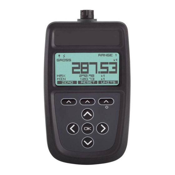
Page 13: Display
Display The PSD has a monochrome dot matrix backlit display and the display may change depending on the display mode. However, the basic operation and positions of items should remain intuitive. The example shown below allows up to three values to be displayed where one is a large, primary value with two secondary values. -
Page 14: Cumulative Zeroing
Soft keys allow you to select from alternative units and to switch between Gross and a zeroed Net value. The state of Gross or Net is displayed above the main value to the left. Cumulative Zeroing Similar to simple mode but has the advantage of being continuously able to zero the main display whilst still viewing the Gross value. -
Page 15: Delta
Soft keys allow you to toggle between Zeroed and Gross values and to Reset the min and max to the current value. The usual Units selection is also available. Delta Similar to Min / Max above but this allows you to focus on the change in value, or noise. The display shows the Delta (Difference between Min and Max values) as the main value while the min and max are displayed underneath. -
Page 16: Icons
Icons The set of icons displayed along the top left of the display are common to all display modes and have the following meanings. A warning is detected. Further investigation of External USB power has been applied. the warning may be required either via the keypad or software. - Page 17 Message Reason INPUT HIGH The mV/V input exceeds the upper limit for the selected sensitivity range of the current calibration range. INPUT LOW The mV/V input is below the lower limit for the selected sensitivity range of the current calibration range. OVERLOAD The input value exceeds the user level set as overload.
-
Page 18: Menu
Menu Menu Basics The menu is accessed by holding the OK key for around one second. It is possible to lock out the menu system so if your handheld does not display a menu it may be that your supplier has locked this feature. Individual features may also have been hidden by your supplier. -
Page 19: Menu Structure
Menu Structure MENU Menu is activated by holding the OK for 1 second. │ │ ├SYSTEM ► System Menu contains settings for display and user interface and │ │ other system wide settings. │ ├DISPLAY Handles settings to do with the display and backlight. ├CONTRAST ►... - Page 20 ├USER INTERFACE ► │ ├KEY ACTIONS ► │ │ │ │ │ │ ├● NONE │ │ │ └● BEEP │ │ │ ├KEYS UP/DOWN ► │ │ │ │ │ │ ├● RANGE SELECTION │ │ │ │ │ │ │ ├●...
- Page 21 ├TIME & DATE ► │ ├TIME NOW ●●● │ │ ├SET DATE ●●● │ │ ├SET TIME ●●● │ │ └DATE FORMAT ► │ │ ├● YYYY/MM/DD FORMAT │ │ ├● DD/MM/YYYY FORMAT │ │ └● MM/DD/YYYY FORMAT │ │ │...
- Page 22 ├MEASUREMENT RATE ► │ │ │ │ │ │ │ ├● 1 SPS One per second │ │ ├● 3 SPS │ │ Three per second ├● 10 SPS Ten per second │ │ ├● 50 SPS Fifty per second │...
- Page 23 │ Information: Name, Mode, Units, Type and last calibration date. ├USER CALIBRATION ► Only available when no active TEDS device is attached ├RANGE NAME ► Only available when no active TEDS device is attached ├RANGE 1 │ Select a Calibration Range item to display and edit its text description ├RANGE 2 │...
- Page 24 ├SET OUTPUT LOW Enter a value in the units (selected above) as the low point of the │ │ known two point calibration. │ │ │ Enter a value in the units (selected above) as the high point of the ├SET OUTPUT HIGH │...
- Page 25 ├● KILOGRAMS Select desired units. │ │ ├● GRAMS │ │ ├● TONNES │ │ ├● POUNDS │ │ ├● OUNCES │ │ └● KILOPOUNDS │ │ ├LOW/HIGH CALIBRATION │ Configure the low and high points to perform calibration. Only a two point calibration can be performed using the keypad.
-
Page 26: Editing Parameter Values
Editing Parameter Values Some menu items allow you to edit / enter a numeric value or text. Editing Numeric Values The following example screen shows what would be displayed for editing the Alarm Low level. The text at the top right states the engineering units of the value being entered. The text at the top inside the box states what parameter is currently being edited. -
Page 27: Editing Text
Pressing and holding this key for over a second then releasing will cancel the current edit. Editing Text The following example screen shows what would be displayed for editing the name of a calibration range. The text at the top inside the box states what parameter is currently being edited. One of the characters will be the current selection and this character will flash alternatively displaying its character and an underlined space. -
Page 28: Connections
Pressing and holding this key for over a second then releasing will cancel the current edit. Connections Strain Bridge Sensor Field Cable Connector Wiring To attach this connector to the handheld, align the white arrow on the connector with the white line on the handheld socket then rotate the locking collar as indicated on the connector. -
Page 29: Field Cable Preparation (4 Wire Shown)
Blue TEDS Black Ground Shield/Screen Grey Cable screen should only be connected to chassis of the sensor. If this cannot be achieved then it should be connected to Excitation –ve. View from solder connector side of the connector Field Cable Preparation (4 Wire Shown) Strip 15 to 20mm of outer sheath. -
Page 30: Connector Assembly
Connector Assembly If a cable is already connected to the connector remember to unscrew the cable clamp before unscrewing the main body of the connector otherwise, you risk twisting the cable and breaking the connections. If the main body is difficult to unscrew it may be easier to lock the connector to the handheld then grip and unscrew the main body in an anti-clockwise direction. -
Page 31: Wiring A Six Wire Strain Bridge Sensor
Wiring a Six Wire Strain Bridge Sensor Where possible six core cable should be used to connect the strain bridge sensor directly to the PSD connector. If the cable has twisted pairs refer to the wiring table above where it is indicated which connections should share a twisted pair. -
Page 32: Where Strain Bridge Sensor Chassis Is Metallic (Or Surrounding Strain Bridge Sensor Structure)
Where Strain Bridge Sensor Chassis is Metallic (or surrounding strain bridge sensor structure) Cable shield should be connected to the strain bridge sensor chassis and remain unconnected at the PSD end. Where There is No Option to Connect to Strain Bridge Sensor Chassis Cable shield should be connected to the PSD Excitation -ve and remain unconnected at the strain bridge sensor end. -
Page 33: Toolkit Configuration
Toolkit Configuration The toolkit (Windows 10 & 11) is used to configure the handheld and offer many more configuration options than the in-built menu system of the handheld itself. Everything that the user can interact with in the Toolkit is highlighted in the blue accent colour. Home When you connect the handheld to the PC using a USB cable it creates a virtual COM port on the PC. -
Page 34: Information
Connect Connect to the device using the selected serial port. button Information This page displays useful information about the connected handheld. Rev: 2 Page 34 2/2024 Instruction Manual PM-6000 Copyright © 2024... -
Page 35: Settings
Settings This page allows you to alter the device settings. Interface Tab Here you can configure the user interface of the handheld and change settings of the backlight and keypad. Item Description Backlight Mode drop- Select the required operational mode for the backlight. Choices are: down The backlight remains off The backlight is on all the while the handheld is turned on... -
Page 36: Key Actions Tab
Brightness Change backlight brightness. Move the slider to set the desired backlight brightness level. A brighter backlight will result in lower battery life. slider Auto-Off Enabled Set to ON to automatically turn off the handheld if keys are not pressed for a specified duration. - Page 37 Note that the left, right, up and down key action options may not be available on some handhelds. Description Item Keypad Press Select the required action when a key is pressed : Action drop - down None Make no sound Beep Briefly sound the buzzer L ef t/Right...
-
Page 38: Clock Tab
Long Press Decimal Places Increase or decrease the number of decimal places displayed for all displayed values using the same units as drop-down list the main display. Disabled No action. Clock Tab Here you can configure the device real-time clock. NOTE: If the batteries are removed for more than half an hour (and the handheld is not being powered by USB) the real time clock may need resetting after the new batteries are fitted. -
Page 39: Import / Export
Item Description Hour Set the handheld internal clock hour. entry field Minute Set the handheld internal clock minute. entry field Year Set the handheld internal clock year. entry field Month Set the handheld internal clock month. entry field Set the handheld internal clock day. entry field Date Format Select the desired date format. -
Page 40: Export Tab
Export Tab This page allows you to perform a simple Export or an advanced Clone Export. Export – This exports device settings to a file on the PC which will contain all data except for configuration data if that section has been locked. Clone Export –... -
Page 41: Export Tab - Clone Export
Export Tab – Clone Export Clone Export is an advanced form of export that offers the ability to export data that may be locked and protected by a password and also allows passwords to be encrypted into the exported file and get applied to the freshly cloned device when imported. -
Page 42: Import Tab
Back Go back to standard export page. button Clone Export Export Clone configuration to a file on the PC. This will open a file dialog box to allow you to button specify where the export will be saved. Import Tab This page allows you import a previously exported file. -
Page 43: Clone Export File
Clone Export File To successfully import a Clone Export file, either the calibration and configuration sections must be unprotected in the connected device or the passwords encrypted in the data file must match those in the protected sections of the connected device. After selecting the file the toolkit will inform you whether the data can be imported and if it can you can chose to click the Import button to perform the cloning action. -
Page 44: Menus Tab
Menus Tab This tab allows you to select which menu items are available from the handheld. Refer to the Menu Structure section to see what functionality the above menu options contain. Note that individual menu items (Those not shown above) are not available for individually hiding. Off –... -
Page 45: Calibration Tab
Calibration Tab This section allows you to configure the available six calibration ranges availability from the menu and whether the range is selectable via the keypad (If that keypad action has been enabled). For the internal six calibration ranges you can choose whether each is selectable and calibratable. Selectable Off –... -
Page 46: Display Modes Tab
Display Modes Tab This section allows you to enable or disable the available six display modes from selection using the keypad (If that functionality has been configured) Note that future display modes may provide the ability to select other modes via the soft keys. The selection options here will not stop that action but only the selection from the keypad. -
Page 47: Units Tab
Units Tab This section allows you to define which units of measure are available for calibration as the base engineering units and also any unit conversions that are selectable from the Units soft key that appears on most display modes. Two lists are displayed. -
Page 48: Custom Units Tab
Note that the decimal places can also be modified (globally for the currently displayed engineering units) by using a long press on the keypad left and right direction keys (If this action has been allowed). Custom Units Tab If the comprehensive list of built in units and automatic conversion does not contain the engineering units you need then this tab allows you to create your own. -
Page 49: Firmware Upgrade Tab
Firmware Upgrade Tab This section allows the firmware in the handheld to be updated. The toolkit must be launched using the ‘Run As Administrator’ option to enable firmware update to work. Item Description Rev: 2 Page 49 2/2024 Instruction Manual PM-6000 Copyright © 2024... -
Page 50: Displays Tab
Firmware Click the button to open the upgrader window. Upgrade button Click Load File button to select the .srec firmware file. Click Start Programming to initiate the update, then follow onscreen instructions. (Remove all power from the device before attempting to reconnect.) Displays Tab This tab allows Display Modes to be assigned to the six available slots. -
Page 51: Mode 1
Mode 1…6 Sub Tab This page shows which Display Mode is selected for each of the available Display Mode slots. Rev: 2 Page 51 2/2024 Instruction Manual PM-6000 Copyright © 2024... - Page 52 Configure the available Display Mode slots with the required Display Modes. Item Description Title Displays the title of the display mode currently selected for this slot. label Description Displays the description of the display mode currently selected for this slot. label Swap With Swap the current display mode with the one in another slot.
-
Page 53: Select New
Select New This pop-up dialog shows all available Display Modes that can be assigned to the currently selected Display Mode Slot. The Toolkit is installed with a library of available Display Modes but also offers the ability to import a custom Display Mode from a file. -
Page 54: Management Tab
Management Tab Access to the entire set of Configuration settings can be locked with a password. Without the password a user cannot change any of the protected settings which include the available Display Modes. This tab allows setting a new password or removing an existing password to protect or release the configuration settings. -
Page 55: Logging
Logging This page allows data from the handheld to be logged to a file and later reloaded to be viewed on the chart. A real-time chart is always visible whether logging is active or not. What is being graphed / logged? Should we be able to select source? Item Description Backlight... - Page 56 Log every 60 milliseconds. 16.6 times per second (16.6 SPS). Log every 100 milliseconds. 10 times per second (10 SPS). Log every 200 milliseconds. 5 times per second (5 SPS). Log every 500 milliseconds. 2 times per second (0.5 SPS). 1000 Log every 1000 milliseconds.
- Page 57 Autoscale Select whether to automatically scale the chart. switch Chart will not automatically scale to suit data as it is added. Click the Reset View button to perform a one off auto scale. Chart will automatically scale to the data as it is added. Select whether to show information popup window as the mouse pointer hovers over data points Show Value switch...
-
Page 58: Measurement
Show Min/Max Select whether to show lines to indicate the minimum and maximum value in the chart data. switch Nothing is displayed. Min and max (Of the currently viewed data) lines are shown in red and green respectively. Load Log File Opens a file dialog to allow you to select a previously logged data file. -
Page 59: Calibration
Each calibration range has its own set of these parameters and they will be remembered the next time the calibration range is selected again. Item Description Calibration Select from the available calibration ranges. Some may have been disabled from the Range drop- Configuration settings. - Page 60 Rev: 2 Page 60 2/2024 Instruction Manual PM-6000 Copyright © 2024...
- Page 61 Sc ale Steady The duration in seconds for the above Scale Steady c alculation. Duration edit field Tare The current value of the Tare . This is subtracted from th e Gross to give Net. edit field Ta re Now Use the current Gr oss value to set the value of T are to give a zero Net value.
-
Page 62: Summary Tab
Summary Tab The summary tab allows you to view a summary of how each range has been calibrated. Item Description This simply indicates which calibration range the row of data applies to. header Name Shows the name assigned to this calibration range. header Units Shows the engineering units that this calibration range has been calibrated in. -
Page 63: Range 1 - 6 Tabs
4-wire Calibration expects a 4 wire measurement. 6-wire Calibration expects a 6 wire measurement. Sensitivity Indicates the sensitivity range selected for this range. header ±7.5 mV/V ±15 mV/V ±30 mV/V ±60 mV/V ±120 mV/V ±240 mV/V ±480 mV/V Date The date when the calibration was performed. header Initials The initials entered at the time of calibration. - Page 64 The common controls will be described here but view the individual sections for specifics regarding each calibration type. It is important to select Sensitivity before starting a calibration. If sensitivity is changed after calibration this may result in incorrect measurement. Item Description Name...
- Page 65 Choose a sensitivity range suitable for the connected strain gauge. Choose the lowest range Sensitivity that exceeds the sensitivity of the connected bridge: Drop down ±7.5 mV/V ±15 mV/V ±30 mV/V ±60 mV/V ±120 mV/V ±240 mV/V ±480 mV/V Units drop Select the engineering units that this calibration range will be calibrated in.
-
Page 66: Calibration Types
Undo Allows the last performed step to be undone. button Import Import a previously exported calibration data file. button Export button Export the current calibration to a file for later import into the same or a different handheld. Calibration Types Depending on the calibration type chosen, the process of actual calibration will differ. - Page 67 This simply indicates which calibration point the row refers to. In this case there is only ever one point. header Offset Click and enter the required offset value. edit field Gain Click and enter the required gain value. edit field Rev: 2 Page 67 2/2024 Instruction Manual PM-6000 Copyright ©...
-
Page 68: Multi-Point
Multi-Point Multi point calibration allows linearization of up to 11 points. Note that you must use the Points [+] button to add one point at a time. Once the input and output values have been set the button will be enabled to allow another point to be added. -
Page 69: Polynomial
Acquire Click to automatically apply the current input value. i.e. apply 10kg and enter 10 in the Output field then click Acquire to automatically enter the current input value. button Output Click and enter the required output value for the given input value. edit field Polynomial This type of calibration consists of a list of values used to perform polynomial linearization. -
Page 70: Management Tab
Value Enter the polynomial value for this point. edit field Management Tab Allows setting a new password or removing an existing password to protect or release the calibration settings. Item Description New Password Allows a new password to be set to protect the calibration settings of the device. This field will be available whether a password exists or not. - Page 71 A forgotten password cannot be recovered and the handheld may need to be returned to the supplier. DO NOT FORGET YOUR PASSWORD! Rev: 2 Page 71 2/2024 Instruction Manual PM-6000 Copyright © 2024...
-
Page 72: Alarm
Alarm The single, global alarm acts on the currently selected calibration range (or TEDS device) and is solely based on the Source selected here. Item Description Source drop- Select the required mode for the backlight to operate in. Choices are: down Gross Base alarm on the Gross value. - Page 73 Latched operation means that the alarm stays active even when the source value is within limits again and requires a manual reset (Via menu) to deactivate. Trigger drop- Select how the responds to the source value relative to the two limits. down alarm Disabled...
-
Page 74: Enclosure
Enclosure The enclosure is made from ABS with a soft polymer over mold for grip and shock absorption. The enclosure, window and keypad should be wiped down with a damp cloth and a mild detergent (such as dishwashing liquid) or isopropyl alcohol. It is weatherproof and can be washed with a damp cloth. -
Page 75: Usb Connection
USB Connection The micro USB socket is waterproof but the rubber dust cover is not intended to be. Before using the USB port please check for and remove any water, sand or other debris. It is safe to rinse the USB socket under a gently running tap. -
Page 76: Fixed Mount
Order Code: ACC-MT-A Fixed Mount This mount is for more permanent fixing for dashboards, desktops and walls. Multiple fixing hole positions secure the base to the surface and a dual ball-jointed arm connects to the handheld enclosure threaded socket. This allows a wide range of positions to be achieved before tightening the arm to fix in place. -
Page 77: Usb Cable
The correctly orientated right angle USB cables are available as an accessory. Order Code: ACC-CB-A Connector Conversion Cable This cable allows the original PSD connector to be plugged in to the new PSDS using a conversion cable. The cable length is 300mm. Order Code: ACC-CB-B... -
Page 78: Specification
Specification Strain Gauge Measurement Parameter Units Note Measurement Method 6 Wire Can accept a 4 wire input. Excitation Voltage Drive Capability 10,000 Sensitivity FSR Ranges ¹ ±7.5 ±480 mV/V Linearity ² ±2 ppm/FSR In high quality operating mode Offset Temperature Stability nV/°C 2.5mV/V Gain Temperature Stability... -
Page 79: Operating Temperature
Battery Life High Quality 1200Hz Operating Temperature °C Range Storage Temperature Range °C Operating Humidity Range Environmental Protection IP64 (With connector mated or unmated) External Dimensions L: 170mm, W: 94mm, H: 42mm Excluding mated connector Weight Including batteries Units of Measure The PSD has a large internal table of engineering units allowing conversion from the calibrated units into various other units, within the same measurement category, as required. - Page 80 fathoms feet furlongs inches kilometers league leagues league light years lines microns µ miles nautical mi n miles millimeters mils nanometers parsec yards Mass kilograms drams dram grains grains grams milligrams ounces pennyweights pounds kilopounds scruples scruple Rev: 2 Page 80 2/2024 Instruction Manual PM-6000 Copyright ©...
- Page 81 slug slug tons long tons metric tonnes tonne tons short sh tn newtons kilonewtons Force newtons kilonewtons millinewtons meganewtons crinals crinal dynes dyne grams force joules per cm J/cm kilograms force kilograms force kp kilograms meter/second² Kg ms² ounces force pounds force poundals tons force long...
- Page 82 dyne/cm² dyncm² foot of water (39°F) ftH20 inch of water (39°F) inH2O gigapascal hectopascal kg force / cm² kgfcm² kg force / m² kgf/m² microbar µbar pascal newton/m² N/m² ounce(avdp)/square inch oz/in² pounds per square foot lb/ft² pounds per square inch tonne per square cm T/cm²...
- Page 83 nautical miles/min n mpm nautical miles/sec n mps Angular Velocity radians/sec rad/s degrees/sec °/s Torsional Stiffness newton meter per radian Nm/rad Torque meter kilogram m kg foot pound ft lb foot poundal ft pd inch pound in lb ounce inch oz-in milli newton meter gram centimeter...
- Page 84 nanoamps rms nA rms kiloamps rms kA rms Current amps milliamps microamps µA nanoamps kiloamps RMS Power watts rms W rms milliwatts rms mW rms microwatts rms µW rms kilowatts rms kW rms Power watts milliwatts microwatts µW kilowatts horsepower Temperature celcius °C...
- Page 85 percent Humidity humidity Frequency hertz kilohertz megahertz Resistance ohms Ω kiloohms kΩ megaohms MΩ Density kilograms per cubic meter kg/m³ grams per litre pounds per cubic foot lb/ft³ Flow Volume litres per second cubic meters per second m³/s cubic meters per hour m³/h gallons per minute cubic feet per minute...
- Page 86 cubic foot per cubic foot ftm³/ftm³ Concentration Mole mole per cubic meter mol/m³ mole per litre mol/L Acceleration meters per second² m/sec² g-force foot per second² ft/sec² Custom custom unit 1 custom1 custom unit 2 custom2 custom unit 3 custom3 custom unit 4 custom4 Undefined...
Need help?
Do you have a question about the PSDS and is the answer not in the manual?
Questions and answers