Advertisement
Quick Links
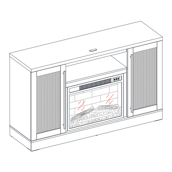
Lexington 54" Fireplace Console
If you have any questions regarding assembly or if parts are missing, DO NOT return this item to the
store where it was purchased. Please call our toll-free customer service number and have your
instructions and parts list ready to provide the model name, part name or factory number:
Or visit our web site 24 hours a day, 7 days a week for product assistance at
THIS INSTRUCTION BOOKLET CONTAINS IMPORTANT SAFETY INFORMATION.
Model # MNFP54RN231DDK
# MNFP54RN231DLT
ADULT ASSEMBLY REQUIRED
Pacific Standard Time: 8:30 a.m. - 4:30 p.m., Monday - Friday
www.whalenfurniture.com
Or e-mail your request to parts@whalenfurniture.com
PLEASE READ AND KEEP FOR FUTURE REFERENCE.
Date: 2024-06-27
1-866-942-5362
Rev. 0001-A
LOT NUMBER:
DATE PURCHASED: /
/
Advertisement

Related Manuals for Whale Lexington MNFP54RN231DDK


Summary of Contents for Whale Lexington MNFP54RN231DDK
- Page 1 LOT NUMBER: DATE PURCHASED: / Lexington 54” Fireplace Console Model # MNFP54RN231DDK # MNFP54RN231DLT ADULT ASSEMBLY REQUIRED If you have any questions regarding assembly or if parts are missing, DO NOT return this item to the store where it was purchased. Please call our toll-free customer service number and have your instructions and parts list ready to provide the model name, part name or factory number: 1-866-942-5362 Pacific Standard Time: 8:30 a.m.
- Page 2 IMPORTANT Before you begin: Open, identify and count all parts prior to assembly. Lay out parts on a flat and non-abrasive surface. You will need the parts identified on page 3, 4 of this instruction manuals. NOTE: IT IS VERY IMPORTANT TO USE GLUE WITH THE DOWELS. EXCESS GLUE CAN BE WIPED OFF WITH A DAMP CLOTH.
- Page 3 Parts and Hardware List Please read completely through the instructions and verify that all listed parts and hardware are present before beginning assembly. A- Top Panel B- Bottom Panel (Qty. 1) (Qty. 1) C- Front Skirting D- Rear Skirting (Qty. 1) (Qty.
- Page 4 Parts and Hardware List Please read completely through the instructions and verify that all listed parts and hardware are present before beginning assembly. Q-Middle Back Panel R- Handle Fireplace Insert Remote Control with Battery (Qty. 1) (Qty. 2) (Qty. 1) (Qty.
- Page 5 Assembly Instructions 1. Unpack the unit and confirm that you have all the hardware and required parts. Assemble the unit on a carpeted floor or the empty carton to avoid any scratch. 2. Securely screw sixteen Cam Bolts (2) into the designated small holes on the Bottom Panel (B), Front Skirting (C) and Side Skirtings (E and F) using a Phillips screwdriver.
- Page 6 Assembly Instructions The cam lock housings face inward. 4. Align and attach the Rear Skirting (D) between the Side Skirtings (E and F) by engaging and tightening two Cam Locks (1). Turn the Cam Locks (1) with a Phillips screwdriver until loked onto the Cam bolts. (Refer to page 2 on Cam Lock system operation supplement).
- Page 7 Assembly Instructions 6. Attach the assembled Front Skirting (C) to both Side Skirtings (E and F) with two Cam Locks (1). 7. Insert two 50 mm Pan Head Screws (6) through the Rear Skirting (D) and securely screw into the Bottom Middle Stretcher (G).
- Page 8 Assembly Instructions The flat surface faces upward 9. Using the pilot holes as a guide, orient and fasten two Triangle Metal Plate (8) at the bottom joints between the Front Skirting (C) and Side Skirtings (E and F) using four 15 mm Pan Head Screws (7) per plate.
- Page 9 Assembly Instructions 180° 11. Turn the assembled base upright. 12. Securely screw four Cam Bolts (2) into the designated small holes on the top surface of the Bottom Panel (B) using a Phillips screwdriver. 13. Securely screw eight Cam Bolts (2) into the designated small holes on both Partitions (I and J) using a Phillips screwdriver.
- Page 10 Assembly Instructions 14. Glue twelve Wood Dowels (3) into the designated holes on both Partitions (I and J) and Middle Trims (M). 15. Attach the Middle Trims (M) to the two Partitions (I and J) respectively with six 32 mm Pan Head Screws (5).
- Page 11 Assembly Instructions 16. Securely screw fourteen Cam Bolts (2) into the designated small holes on the Top Panel (A) and Media Shelf (K) using a Phillips screwdriver. 17. Glue sixteen Wood Dowels (3) into the inner holes on both Side Panels (H), Middle Crossbars (L) and Media Shelf (K) as shown.
- Page 12 Assembly Instructions The cam lock housing face inward 18. Orient and attach one Middle Crossbar (L) to the Media Shelf (K) by engaging and tightening three Cam Locks (1) using a Phillips screwdriver. The wood dowels will face the top panel The cam locks face inward 19.
- Page 13 Assembly Instructions 22. Ask for assistance to position the Top Panel (A) onto the inserted wood dowels on the previous assembly properly and fasten them into place with seven Cam Locks (1). The hinges face inward and are located at front 23.
- Page 14 Assembly Instructions Floor Leveler 24. Align and attach the Bottom Panel (B) to the assembled Side Panels (H) by engaging and tightening four Cam Locks (1) with a Phillips screwdriver. 25. Insert four 50 mm Pan Head Screws (6) through the mounting holes on the Bottom Panel (B) and securely screw into the Partitions (I and J).
- Page 15 Assembly Instructions 180° 26. Now, go back and securely tighten all the cam locks and screws. Make sure that all the parts are tight and there are no gaps between the parts. This will help keep the unit square. 27. Ask for assistance to flip around the previous assembly at its front edges as shown. 28.
- Page 16 Assembly Instructions 31. Attach one Handle (R) to the front of each Door (O) with two 22 mm Handle Bolts (14). Tighten with a Phillips screwdriver. Vertical Horizontal Depth Adjustment Adjustment Adjustment 32. Pick up the Doors (O) and attach the extended hinge arms to the hinge bases pre-installed on the Side Panels (H).
- Page 17 Assembly Instructions 35. Plug Cam Lock Covers (11) onto the visible Cams Locks to conceal the cams. 36. Stick the Rubber Bumpers (13) onto the outer front corners of both Doors (O) where the Partitions (I and J) are in contact with. Top trim Side trim 37.
- Page 18 Assembly Instructions NOTE: To prevent your TV from tipping, you must install the acrylic TV stopper if you place a flat panel television on the top panel. Otherwise, skip to next step. 40. Remove the paper backing of Acrylic Stopper (12), then properly align the acrylic stopper into the cutout on the acrylic stopper template on the front of the Top Panel (A).
- Page 19 Assembly Instructions Wooden stud Wall Long screw Wall Wall Metal bracket Short screw Connector Wall Steel cable Floor leveler Tools required (not provided): Phillips screwdriver, stud finder, tape measure, pencil, power drill and 1/8” drill bit. 42. Ask for assistance to position the assembled fireplace at the desired location against a wall. If necessary, adjust the floor levelers to correct the tilting and level the doors.
-
Page 20: Care And Maintenance
Care and Maintenance Use a soft, clean cloth that will not scratch the surface when dusting. Use of furniture polishes is not necessary. Should you choose to use polishes, test first in an inconspicuous area. Using solvents of any kind on your furniture may damage the finish. ... -
Page 21: Quality Guarantee
M A X I M U M R E C O M M E N D E D W E I G H T L O A D S MANUFACTURER: Whalen Furniture Manufacturing CATALOG : Lexington 54” Fireplace Console MODEL #: MNFP54RN231DDK / MNFP54RN231DLT FITS MOST FLAT PANEL TVS UP TO 165.1 cm / 65 in.
Need help?
Do you have a question about the Lexington MNFP54RN231DDK and is the answer not in the manual?
Questions and answers