Advertisement
Interface Manual
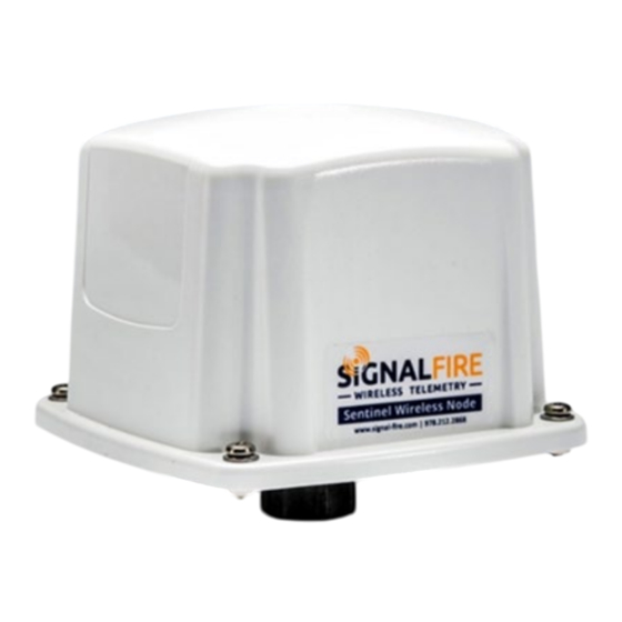
Sentinel Node HART
The SignalFire Sentinel Node is a device with the following features:
-
Powers a single HART sensor at 12.5VDC or 18.0VDC (software selectable)
-
Low power operation from an on-board DC-DC power supply
-
Sends data to a SignalFire Buffered Modbus Gateway
-
Settable Modbus ID
-
AES128bit Encryption
Rev 1.16
SignalFire Model: Sentinel-HART-DC
SignalFire Telemetry
1
Advertisement
Table of Contents

Summary of Contents for SignalFire Sentinel Node HART
- Page 1 Interface Manual Sentinel Node HART SignalFire Model: Sentinel-HART-DC The SignalFire Sentinel Node is a device with the following features: Powers a single HART sensor at 12.5VDC or 18.0VDC (software selectable) Low power operation from an on-board DC-DC power supply Sends data to a SignalFire Buffered Modbus Gateway...
-
Page 2: Specifications
WARNING: The use of any parts not supplied by the manufacturer violates the safety rating of the equipment. L’utilisation de toute composantes différentes du manufacturier élimine la sécurité intrinsèque du produit Rev 1.16 SignalFire Telemetry... - Page 3 Markings Device Label DC Converter Rev 1.16 SignalFire Telemetry...
-
Page 4: Connections And Components
If this button is pressed the Sentinel will apply power to the sensor for the configured sensor on time and scan for the HART sensor. If the Hart sensor is detected the HART_STATUS LED will blink once and its data will be read. The Sentinel will also send the collected sensor data to the gateway. Rev 1.16 SignalFire Telemetry... - Page 5 Modbus ID setting Sensor on time/supply voltage All settings are made using the SignalFire Toolkit PC application and a serial programming cable. The Modbus ID can also be set using the DIP switch (in older models only). WARNING: Perform the steps in this section (Setup) in a safe location only.
- Page 6 1 Serial Port Settings 2 Sentinel Information 3 Set Corporate ID / Encryption Key 4 Status of Last Operation 5 Reported Sensor and HART Values 6 Sentinel Settings 7 Alarm Settings Rev 1.16 SignalFire Telemetry...
- Page 7 To set up a legacy Sentinel to use encryption, click the checkbox labeled Enable Encryption inside the Set Corporate ID box. All newer Sentinels come with this option enabled with “signalfire” as the default encryption key. Corporate ID...
- Page 8 Power and Sensor Connections Wiring Requirements Follow these guidelines when connecting sensors to the SignalFire node. See pictures for proper wire routing examples. Cables entering the enclosure must be run as pictured. DC power cable should be run through the cable gland and gland should be tightened.
- Page 9 A single sensor operating in HART multi-drop mode may be connected to the Sentinel Node. The HART Sensor must be configured for HART ID 1. The Sensor HART ID may be configured using the SignalFire Toolkit; see Page 10 for details. HART+ HART- The HART sensor is a 2-wire interface between the Sentinel Node and the HART sensor.
-
Page 10: Sensor Settings
The default is 2 seconds which is used for most pressure and other simple sensors. Radar sensors often require a longer warm-up time. Contact your sensor manufacturer or SignalFire for details. It is possible to power a HART sensor full. This is useful for rapid data collection on a sensor that has a long warm-up time. - Page 11 SV rises above 15.4 it sets the High Alarm register to 1. Because the sensor is always on, if either threshold is crossed, the Sentinel will check in every 15 seconds instead of every minute as configured. Rev 1.16 SignalFire Telemetry...
- Page 12 Remote Modbus Register Mapping The Sentinel Node sends data to a SignalFire Telemetry Modbus Gateway. The data that is sent to the gateway is available at the gateway in registers where it can then be read by a Modbus RTU.
- Page 13 Analog card comm failure User sec. level is locked Sensor zero address detected Factory sec. level is locked Sensor multiple addresses Display available Sensor missing address Calibration mode is active Sensor bus short circuited Readout is valid Rev 1.16 SignalFire Telemetry...
- Page 14 Element 13 Data 44043 4042 Element 14 Data 44045 4044 Element 15 Data 44047 4046 Element 16 Data *If an Endress+Hauser Prothermo NMT81 sensor is installed, it will automatically be detected and send these additional registers. Rev 1.16 SignalFire Telemetry...
- Page 15 ATTENTION: Le produit Sentinel doit être installé dans un endroit libre de hautes vibrations. Sans quoi avec le temps, des possibles dommages pourraient compromettre la sécurité intrinsèque du produit. Les installations sur équipement en vibration constante (pompes, compresseurs) doit à tout prix être éviter. Rev 1.16 SignalFire Telemetry...
- Page 16 Debug and configuration information is available if a connection is made via the debug port on the main board. A USB converter cable (available from SignalFire) must be used for this interface. Debug and advanced configuration may be done using the SignalFire Toolkit PC application.
-
Page 17: Product Disposal Information
Revision History Revision Date Changes/Updates 1.13 5/1/23 Initial release – forked from Sentinel-HART manual 1.14 10/10/24 Added register map for E&H Prothermo NMT81 sensor. 1.15 10/14/24 Corrected E+H Prothermo NMT81 register map 1.16 11/1/2024 Add disposal information Rev 1.16 SignalFire Telemetry... - Page 18 APPENDIX - FCC and IC Statements Changes or modifications not expressly approved by SignalFire Telemetry, Inc could void the user’s authority to operate the equipment. This device complies with Part 15 of the FCC Rules. Operation is subject to the following two conditions: (1) this device may not cause harmful interference, and (2) this device must accept any interference received, including interference that may cause undesired operation.
Need help?
Do you have a question about the Sentinel Node HART and is the answer not in the manual?
Questions and answers