
Subscribe to Our Youtube Channel
Summary of Contents for Cetetherm AquaCompact 30
- Page 1 Installation, service and operating instruction Cetetherm AquaCompact DHW heater Manual AquaCompact EN 2024 05 14.docx...
- Page 2 This manual is published by Cetetherm. Cetetherm can without further notice make changes and improvements to the content in this manual if it is necessary due to printing mistakes, wrong information or changes in the hardware or software. All these types of changes will be included in future release of...
-
Page 3: Table Of Contents
Cetetherm AquaCompact Installation, service and operating instructions Contents Product overview ........................5 Working pressure and temperature ......................6 Packing format............................6 Options ..........................6 2PSA primary kit – Thermostatic 2-way control valve featuring ..............6 2PE primary kit - Electrical 2-way control valve featuring .................6 3PE primary kit - Three-way control valve including .................7... - Page 4 Special instructions for options ..................51 18.1 Special instructions for 2PSA primary kits ..................... 51 18.2 Special instructions for 2PE primary kit ....................51 Commissioning report ......................52 Declaration of Conformity ....................53 Warranty ..........................54 How to contact Cetetherm ........................54...
-
Page 5: Product Overview
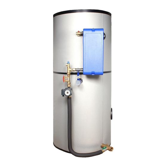
Cetetherm AquaCompact Installation, service and operating instructions Product overview The basic version of the Cetetherm AquaCompact DHW heater, semi-instantaneous system includes: AquaCompact 30 – basic format AquaCompact 60 – basic format AquaCompact M3 – basic format Aquatank Storage tank, 316Ti stainless steel storage tank,... -
Page 6: Working Pressure And Temperature
Cetetherm AquaCompact Installation, service and operating instructions Working pressure and temperature Primary side Secondary side Version Max working Max temperature Max working Max temperature pressure (bar) (°C) pressure (bar) (°C) 2PSA Kit (CB/FB/M3) 2PE kits (CB/FB/M3) 3EPkits (CB/FB/M3) Packing format AquaCompact is delivered in three packages: •... -
Page 7: 3Pe Primary Kit - Three-Way Control Valve Including
Cetetherm AquaCompact Installation, service and operating instructions Actuator Control valve Control box mounted on its support 3PE primary kit - Three-way control valve including • One 3-port control valve, PN16 • One primary pump, PN10 • One actuator, 24V AC feed-in and 0-10V DC controller current •... -
Page 8: Installation
Cetetherm AquaCompact Installation, service and operating instructions Installation Siting The AquaCompact hot water heater shall be installed in a dry place where room temperature is below 40°C, and ideally in ventilated premises. AquaCompact is placed preferably on a sub-base footing. -
Page 9: Commissioning
Cetetherm AquaCompact Installation, service and operating instructions Bottom section connection, shut-off valve inserted between the conduit hose and the cold water inlet fixture. Commissioning • Flood the various circuits and flush bleed the pumps. • Power-up. • Set the secondary (charging) flow rate using the setting valve (read-off + setting) NOTE: When first heated, the water in the tank will expand, increasing the pressure. -
Page 10: Electrical Connections
Cetetherm AquaCompact Installation, service and operating instructions Electrical connections All devices shall be connected in compliance with the governing standards. All work on control box and other electrical components must be done by qualified people. The main electrical box should be equipped with short-circuits protection Basic model with or without option 2PSA The charging pump has to be powered constantly. -
Page 11: Electrical Installation Of Control Box, Option
Cetetherm AquaCompact Installation, service and operating instructions Electrical installation of control box, option Power supply the control box with 230VAC 50 Hz. The control box with the controller Micro 3000 is called the secondary control box. Power supply the control box with 230V 50 Hz + Earth, using electric protection in the main electric power box. -
Page 12: Electrical Wiring Diagram, Option 2Pe
Cetetherm AquaCompact Installation, service and operating instructions Electrical wiring diagram, option 2PE Remote contact: Volt free contact between M and D5 terminals on the temperature controller PCB. Open Contact (by default) = unit operating normally, Closed contact= unit in standby = no temperature... - Page 13 Cetetherm AquaCompact Installation, service and operating instructions NOTE: If 230V 3pts actuator wiring, see 18 Special instructions for options.
-
Page 14: Electrical Wiring Diagram, Option 3Pe
Cetetherm AquaCompact Installation, service and operating instructions Electrical wiring diagram, option 3PE Remote contact: Volt free contact between M and D5 terminals on the temperature controller PCB. Open Contact (by default) = unit operating normally, Closed contact= unit in standby = no temperature... - Page 15 Cetetherm AquaCompact Installation, service and operating instructions...
-
Page 16: User Instruction Control Panel Micro 4000
Cetetherm AquaCompact Installation, service and operating instructions User instruction control panel Micro 4000 When the unit is power supplied, wait one minute before navigating into the menu. Designation key to display firmware/software versions. It is equipped of an orange LED if point in manual OR Green flashing if modbus connection with BMS writing priority. -
Page 17: Display Settings (Hmi)
Cetetherm AquaCompact Installation, service and operating instructions Display settings (HMI) 1. Press a few seconds on « Escape » key to access to HMI 1 /2 settings: HMI settings Then press (✓) key Local connection 2. Press on key then on ✓ key to change backlight colour. -
Page 18: End User Mode
(UTD, Standards EN, ISO etc.) All countries have different rules for how hot or cold tap water should be. Cetetherm recommends the hot water temperature is at least 55°C and a hot water recirculation not less than 50°C. At a temperature below 50°C there is a risk of bacterial growth. Note that at temperatures above 60°C the risk of scalding increases. -
Page 19: Technician Access Level
Cetetherm AquaCompact Installation, service and operating instructions 4. Now, display has changed to « Enable ON » and Safety function the alarm key green flashes, indicating a function is Enable on-going. Pump signal setpoint 100%* Valve signal setpoint 50%* 5. To stop the function from line#1 of safety function menu, press twice on ✓ key (OFF state on display). -
Page 20: Log Out
Cetetherm AquaCompact Installation, service and operating instructions 9.2. Log out You don’t have to wait 10 minutes until logging out. It is possible to log out at any time. For that : 1. Press a few seconds on ✓ key 2. - Page 21 Cetetherm AquaCompact Installation, service and operating instructions 6 / t STANDARD … 1. From the main menu and using / keys, go to line #6 as shown : Then press ✓ key to access to S1 sub-menu S1 : Actual setpoint 60°C...
-
Page 22: High And Low S1 Temperature Alarm
Cetetherm AquaCompact Installation, service and operating instructions Then press « Esc » key to get back one step and press several times key to go to line #10: Copy Monday from Tue.to Sun. Press ✓ key. In ours ample, we want to duplicate values except Saturday and Sunday. -
Page 23: S1 Temperature Controller
Cetetherm AquaCompact Installation, service and operating instructions 1. Go to line #3 of S1 Menu and press ✓ key to access to high alarm Delta T setting. Press / keys to change the value. 3 / 8 ... -
Page 24: Thermal Treatment Function
Cetetherm AquaCompact Installation, service and operating instructions 9.5. Thermal treatment function Principle : S1 temperature setpoint is raised (70°C by default) as per a clock program, for a set duration, in general between 1 and 2 hours, depending of secondary flow rate and storage tank capacity. -
Page 25: Safety Function
Cetetherm AquaCompact Installation, service and operating instructions Example : Sec. Flow rate Q=2m3/h, Tank volume 500L=V=0,5m3 and recycling flow rate=q=1000 l/h. Tank loading time, so minimal treatment duration = V/(Q-q) Let 0,5/(2-1)=0,5 hour. If you wish to maintain at this temperature for 1 hour, you need 1h30 duration (0.5h+1h) or 90 minutes. -
Page 26: Eco Function
Cetetherm AquaCompact Installation, service and operating instructions When the safety function is ON, the Alarm(s)/Function(s) button green flashes. 9.7. ECO function. Eco function principle: When control valve is sufficiently closed (valve signal<=”Y1 setpoint”) during a sufficient long time (“switch-on delay”), primary pump(s) switch(es) off and primary mixing valve closes down. -
Page 27: Pump(S) Menu
Cetetherm AquaCompact Installation, service and operating instructions 9.8. Pump(s) menu This menu appears if at least one pump is declared. Otherwise it is not visible. Settings : 1. From the main menu and using / keys, go to line “Pump(s) l / t ... -
Page 28: Modbus Rtu Communication Menu
Cetetherm AquaCompact Installation, service and operating instructions 9.10. Modbus RTU Communication Menu Be sure modbus cable wires are connected on T1 terminal (upper left corner of the control box) to get Modbus communication. Wiring made on terminals labelled A+ and B-. If cable lengh exceeds 3 meters, it is recommended to use a shielded cable, connecting shiled to REF terminal. - Page 29 Cetetherm AquaCompact Installation, service and operating instructions Modbus parameters’ list : COMMUNICATION POINTS Default values * In case of multiple controllers, change ModBus slave number Speed / Vitesse : 19200 MODBUS * En cas d’echangeur en cascade changer le N° d' esclave du mode bus...
-
Page 30: Wired Inputs / Outputs Menu
Cetetherm AquaCompact Installation, service and operating instructions 9.11. Wired Inputs / Outputs menu This sub-menu is very useful to commission or to diagnostic an unit : check valve is opening/closing, check pump is running or check contacts’ relays. It is more powerful than the « Test sequence » sub-menu. -
Page 31: Configuration Access Level
Cetetherm AquaCompact Installation, service and operating instructions 1/12 Binary (or digital) outputs BO-IO Aut.st As for analog outputs, it is possible to force these contacts to ON or ------- T10 CONNECTOR -------- OFF. To do that, pass from AUTO to MANual mode. -
Page 32: Configuration Menu
Cetetherm AquaCompact Installation, service and operating instructions 10.3. Configuration menu Note ! If Reseted contrôler or spare part controller, pump(s) and sensor(s) number MUST be configured using this sub-menu. Settings : 1. From the main menu, use / keys to go to the line l / t ... - Page 33 Cetetherm AquaCompact Installation, service and operating instructions … Default value is General alarm: will be activated for any default Possible values are : No action Nothing ✓General alarm Any default (default value) High temperature alarm on S1 High T° alarm Low temperature alarm on S1 Low T°...
-
Page 34: Alarms/Functions And Acknowledgement
Cetetherm AquaCompact Installation, service and operating instructions ** If Timer selected, and extra line will be displayed. This will add a clock program, with 6 possible daily time schedules to ON/OFF relay contact. Please refer to S1 clock program as settings are similar (except they apply to ON/OFF instead of a setpoint value). -
Page 35: Production Reset
Cetetherm AquaCompact Installation, service and operating instructions 12. Production RESET If lot of parameters have been changed (PID, functions…) and you want to find back all default settings at once, you should proceed the production reset. Access code is 2000. -
Page 36: Trouble Shooting
Cetetherm AquaCompact Installation, service and operating instructions 13. Trouble shooting FINDINGS PROBABLE CAUSES REMEDIES Controller doesn’t start No power from mains or PCB Check FU5 (230V transfo), FU7 (24VDC transformer transfo) and mains supply Pump(s) not operating Locked rotor or damaged Force to rotate. -
Page 37: Maintenance And Repairs
Only replace any defective parts with the original spare parts. Please contact your Cetetherm distributor for spare parts, note serial number and model designation. Maintenance work must be carried out by a qualified and authorized technician. -
Page 38: Clean The Heat Exchanger Plates (P Series)
7. Tighten up the exchanger, using the tightening length as initially. 8. Make sure the thermometer pocket of the control sensor is properly cleaned. Ask your local Cetetherm Company for more information on maintenance procedures, disassembly, cleaning, remounting; see the Cetetherm instructions manual, document reference number 1644725-01. -
Page 39: Open The Control Box
CIP connector: 3/4‘’ Cetetherm recommends the use of a pre-fitted Cetetherm CIP 20-type cleaning unit together with a specific cleaning agent, such as AlfaPhos that is environmentally friendly. There are several product solutions available depending on the cleaning job to be tackled. Use a neutralizing solution, such as AlfaNeutra, before rinsing. -
Page 40: Pumps' Number
Cetetherm AquaCompact Installation, service and operating instructions The service work must be carried out by an authorized service technician. Turn off the power supply before starting to work. Picture 1 Fuse Protection 230V Transfo. primary 24V AC 24V DC (Power PCB protection) -
Page 41: Remote Control Contact
Cetetherm AquaCompact Installation, service and operating instructions • Relay 2 wiring: Terminals 38 (C) and 39 (NO) on PCB ADE_430. • Relay 3 wiring: Terminals 40 (C) and 41 (NO) on PCB ADE_430. Please refer to Electric wiring diagram chapter for connections. If 230V AC through relay, do not exceed 2A by relay. -
Page 42: Assembly Of The Charging Kit To The Aquatank
Cetetherm AquaCompact Installation, service and operating instructions Assembly of the charging kit to the Aquatank NOTE: The photos are non-binding – changes are liable to made without notice. 1. Start by fitting the insulation onto the tank. The insulation must be mounted before the tank is definitively connected up. - Page 43 Cetetherm AquaCompact Installation, service and operating instructions 8. Set an initial position by fitting the threaded 9. Readjust the assembly to make sure rod of the support into the tube and screwing the exchange is perfectly vertical and the union connector at the exchange outlet parallel to the tank shell.
- Page 44 Cetetherm AquaCompact Installation, service and operating instructions 12. Connect the upper flexible pipe to the pump. 13. Repeat the procedure to link the bottom of the hose to the cold water inlet fixture located toward the base of the tank.
-
Page 45: Specific Points For Assembling The M3 Charging Kit
Cetetherm AquaCompact Installation, service and operating instructions 15.1 Specific points for assembling the M3 charging kit The kit is anchored onto a support sleeve via a clamp collar that should be positioned to the middle of the sleeve before being adjusted and tightened. Use the adjustable support fixture on the exchanger when guiding the kit into the correct position. -
Page 46: Mounting The Flexible Hose Onto The Tank
Cetetherm AquaCompact Installation, service and operating instructions 15.2 Mounting the flexible hose onto the tank... -
Page 47: Flowcharts
Cetetherm AquaCompact Installation, service and operating instructions Flowcharts 16.1 Flowchart AquaCompact Description Description Primary supply Balancing valve Primary return Charging pump (secondary) Heat Exchanger DHWC pump (recirculation pump) Shut-off valves Non Return Valve Safety valve Domestic Hot water Drain valve... -
Page 48: Flowchart Aquacompact With Primary Kit 2Psa
Cetetherm AquaCompact Installation, service and operating instructions 16.2 Flowchart AquaCompact with primary kit 2PSA Description Description Immersion temperature sensor 2-port control valve with self-acting actuator 16.3 Flowchart AquaCompact with primary kit 2PE Description Description Immersion temperature sensor Control box 2-port control valve with actuator... -
Page 49: Flowchart Aquacompact With Primary Kit 3Pe
Cetetherm AquaCompact Installation, service and operating instructions 16.4 Flowchart AquaCompact with primary kit 3PE Name Name Immersion temperature sensor V(cv) Closing valve (primary side valves) CIP sensor 3-port control valve with actuator Control box Primary pump Temperature sensor Mixing bottle... -
Page 50: Wiring The Charging Pump
Cetetherm AquaCompact Installation, service and operating instructions Wiring the charging pump Note: The charging pump has not been wired before delivery. The five wires cable connected to the control box must be wired to the charging pump. Please proceed as follow: Ensure the system is not connected to the main power supply. -
Page 51: Special Instructions For Options
Cetetherm AquaCompact Installation, service and operating instructions Special instructions for options 18.1 Special instructions for 2PSA primary kits Please refer to the guide supplied with the thermostatic control valve. 2.1 2PSA primary kit – Thermostatic 2-way control Always position the black slot upwards, see valve featuring. -
Page 52: Commissioning Report
Cetetherm AquaCompact Installation, service and operating instructions Commissioning report All parts are not applicable to the AquaCompact. -
Page 53: Declaration Of Conformity
Cetetherm AquaCompact Installation, service and operating instructions Declaration of Conformity PED 2014/68/EU art. 4.3, LVD, EMC, RoHS Declaration of Conformity Déclaration de Conformité Konformitätserklärung Conformiteitsverklaring Manufacturer / Fabricant / Hersteller / Fabrikant: Cetetherm SAS Route du Stade ZI du Moulin, 69490 Pontcharra sur Turdine, France •... -
Page 54: Warranty
Also excluded from the warranty: Fitting costs, refitting costs, packaging, transport, and any accessories or equipment not manufactured by Cetetherm, which will only be covered by any warranties issued by said third-party manufacturers. Any damage caused by connection errors, insufficient protection, misapplication or faulty or careless operations. - Page 56 Cetetherm sas ZI du Moulin, Route du Stade 69490 Pontcharra sur Turdine - France www.cetetherm.com...
Need help?
Do you have a question about the AquaCompact 30 and is the answer not in the manual?
Questions and answers