
Related Manuals for Spitzer SPZ-M300-S Series


Summary of Contents for Spitzer SPZ-M300-S Series
- Page 1 User Manual SPZ-M400/500-S MICRO INVERTER Carefully read this inverter user instructions before using. Read and save these instructions.
- Page 2 TRADEMARKS and other trademarks are the trademarks or registered trademarks of all other trademarks mentioned herein are the properties of their respective owners.
-
Page 3: Table Of Contents
Contents CONTENTS 1. Safety Instructions ..............................1 1.1 Safety Instruction .................................1 1.2 Symbol Description ................................1 1.2.1 Symbols Used in the Manual ............................1 1.2.2 Other Symbols .................................2 1.3 Radio Wave Interference Statement ..........................2 2. Product Introduction .............................. 3 2.1 Photovoltaic On-Grid System ............................3 2.2 Microinverter ..................................3 2.3 1-in-1 Microinverter System ............................4 2.4 Communication Technology ............................4... - Page 4 Contents 5.4 End-of-life Disposal ................................16 6. Human-Computer Interaction ..........................17 6.1 Installing the App ................................17 6.2 APP User manual ................................17 6.3 System debugging ................................17 7. Appendix ................................... 18 7.1 Technical Specifications ..............................18 7.2 Grid Support Details ...............................19 7.3 Wiring Diagram .................................21 7.4 Installation Map .................................21...
-
Page 5: Safety Instructions
1. Safety Instructions 1. Safety Instructions SPZ-M300-S, SPZ-M350-S, SPZ-M400-S, SPZ-M450-S, SPZ-M500-S series microinverters can efficiently convert direct current into alternating current that meets the requirements of the power grid and feed the power into the power grid. They are designed and tested in strict accordance with relevant national safety standards. -
Page 6: Other Symbols
1. Safety Instructions CAUTION • To avoid potential safety hazards, the corresponding instructions must be strictly followed. NOTICE • This operation is prohibited, and relevant personnel should stop the operation. 1.2.2 Other Symbols Symbol Description Caution When the device is running, do not step within 0.2 m of its periphery. High Voltage The high voltage generated by microinverter can endanger life. -
Page 7: Product Introduction
2. Product Introduction 2. Product Introduction 2.1 Photovoltaic On-Grid System SPZ-M500-S The on-grid system diagram of series microinverter is as follows: 2.2 Microinverter SPZ-M300-S, SPZ-M350-S, SPZ-M400-W, SPZ-M450-S, SPZ-M500-W series are 1-in-1 microinverters, which can connect one photovoltaic modules. They are module-level photovoltaic inverters with module-level monitoring function. -
Page 8: 1-In-1 Microinverter System
2. Product Introduction and the user is provided with module-level monitoring through the Web or App application to realize remote operation and maintenance. 2.3 1-in-1 Microinverter System The DC side can choose a microinverter series according to the number of connected photovoltaic modules. -
Page 9: Inverter Size And Termnial Instruction
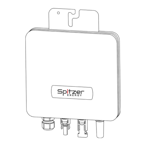
2. Product Introduction • IP67 enclosure, 6000V surge protection for higher reliability. 2.6 Inverter Size and Termnial Instruction A: AC Branch Connector B: Antenna C: DC terminal... -
Page 10: Installation
3. Installation 3. Installation Each microinverter is installed on a mount just below the solar module panel. The low-voltage DC line on the panel side of the solar module can be directly connected to the microinverter, but it must be protected from direct sunlight, rain, snow, ultraviolet rays, etc. A clearance of at least 20mm should be left around the microinverter enclosure to ensure ventilation and heat dissipation. -
Page 11: Installation Procedures
3. Installation 3.3 Installation Procedures 3.3.1 How to Make a T-Junction Bus • Step 1: Prepare several sections of T-junction connecting wires according to the number of microinverters to be installed on site. • Step 2: Removing the T-junction cable at the end. Use the T-knot removal tool to remove the Loosen the inner screw, unscrew the nut, and lower cover. -
Page 12: Microinverter Installation
3. Installation • Step 4: Secure the T-junction cable Put the T-junction connecting wire on the guide rail and fix it with cable tie. CAUTION • Nut tightening torque: 2.5±0.5N·m, Screw tightening torque: 0.8±0.1N·m, Do not over-tighten, Do not damage the sealing ring in the T-junction connector during assembly and disassembly. -
Page 13: Connect Pv Module
3. Installation 3.3.4 Connect PV module • Step 1: Install the PV module above the microinverter. • Step 2: Connect the DC output cable of the PV module with the input side of the microinverter. CAUTION • Ensure that the output current and voltage of the PV modules are consistent with the inverter. -
Page 14: Operate And Power On
3. Installation 3.3.6 Operate and Power On • Step 1: Close the main Grid circuit breaker. • Step 2: Close the AC circuit breaker of each microinverter branch, and the system will automatically generate power after about 2 minutes. • Step 3: Set up monitoring system on Smart PV Cloud Platform. -
Page 15: Fault Clearance
4. Fault Clearance 4. Fault Clearance Only qualified professionals can implement the following troubleshooting operations when the microinverter solar system is not working properly. 4.1 Status indication and error reporting 4.1.1 Start indicator When the DC side of the microinverter is powered on for the first time : •... - Page 16 4. Fault Clearance Fault code Fault description Solution 1.Occasionally, it may be a short-term power grid abnormality. When the power grid is normal, it will resume work without manual intervention. 2.If all the microinverters in the power station have 3082 Island protection frequent islanding alarms, please contact the power bureau to confirm whether there is indeed an...
-
Page 17: On-Site Inspection (Qualified Installers Only)
4. Fault Clearance Fault code Fault description Solution 1.If the input DC voltage is too high, please ensure that the input photovoltaic module voltage flow is PV1-PV4 absorption capacity overvoltage not higher than the maximum input voltage of the 3098 Inverter bridge 1 hardware microinverter. - Page 18 4. Fault Clearance technical parameter table of the user manual. • Step 7: If the problem persists, please call customer support number. Precautions for routine maintenance: DANGER • Do not attempt to repair the microinverter, if troubleshooting fails, return it to the factory for a replacement.
-
Page 19: Maintenance Guide
5. Maintenance Guide 5. Maintenance Guide 5.1 Routine maintenance • Only authorized personnel are allowed to perform maintenance operations and are responsible for reporting abnormal conditions. • Wear personal protective equipment for maintenance operations. • In normal operation, check the environment. Make sure that the environment does not meet the normal working requirements of the microinverter due to time changes, and ensure that the microinverter is not exposed to harsh weather and is not covered by foreign objects. -
Page 20: End-Of-Life Disposal
5. Maintenance Guide 5.4 End-of-life Disposal If the device is no longer in use or needs to be stored for a long time, please make sure that the packaging is intact. Store the device in a well-ventilated indoor area that will not cause damage to device components. -
Page 21: Technical Specifications
7. Appendix 7. Appendix 7.1 Technical Specifications SPZ-M500-S SPZ-M300-S SPZ-M400-S SPZ-M450-S SPZ-M350-S Product Model Input (DC) Typical module compatibility 240-450 ⁺ W 280-525 ⁺ W 320-600 ⁺ W 360-675 ⁺ W 400-670 ⁺ W MPPT voltage range 16 - 60V Max. -
Page 22: Appendix
7. Appendix SPZ-M400-S SPZ-M500-S SPZ-M350-S SPZ-M300-S SPZ-M450-S Product Model General Data Cooling Natural convection - No fans Weight 1.7kg Relative humidity 0-100% RH Relative humidity Features Communication Sub-1G Monitoring Cloud Type of isolation High frequency transformers, Galvanically isolated 7.2 Grid Support Details SPZ-M300-S, SPZ-M350-S, SPZ-M400-W, SPZ-M450-S, SPZ-M500-W Microinverter is a grid support interactive inverter, which is also known as a Grid Support Utility Interactive Inverter. - Page 23 7. Appendix Low/High Frequency Ride Through (L/H FRT) and Must Trip Settings System Range of Ride- Ride-Through Frequency Trip Time Adjustable Trip Region Through Operational Default Default (s) Time Default Until (s) Mode Settings Through No High Frequency 2 (HF2) f >...
-
Page 24: Wiring Diagram
7. Appendix 7.3 Wiring Diagram Wiring Diagram 7.4 Installation Map 7.5 Contact Information If you have any questions about this product, please contact us ! In order to provide you with faster and better after-sales service, we need your assistance to provide the following information: Device model:...
Need help?
Do you have a question about the SPZ-M300-S Series and is the answer not in the manual?
Questions and answers