
Summary of Contents for Mikasa MCD-T18H-PLUS
- Page 1 OPERATING INSTRUCTIONS MIKASA FLOOR AND ROAD SAW MCD-T18H-PLUS Version 1.0 (November 2024) FOR MORE INFORMATION EXCLUSIVE TO CONTACT US ON 1300 353 986 OR VISIT flextool.com.au...
- Page 2 CONCRETE CUTTER MCD-T18H-PLUS OPERATION MANUAL 602-02901 *602-02901* http://www.mikasas.com...
-
Page 3: Table Of Contents
TABLE OF CONTENTS INTRODUCTION ..................MACHINERY OVERVIEW ............... WARNING SIGNS ................... CAUTIONS FOR SAFETY............... General Cautions Precautions Refueling Precautions Of Location And Ventilation Precautions Before Starting Precautions During Work Precautions Of Lifting Precautions Of Transport And Storage Precautions Of Maintenance Decals Position Decals List 4.10... -
Page 4: Introduction
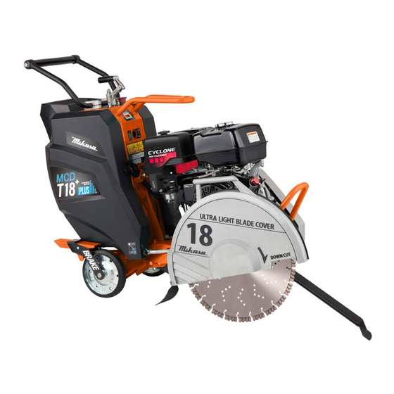
Application Mikasa Concrete Cutter is used to cut the concrete or asphalt road surface by Diamond Blade that is attached on its Blade shaft. Please choose machine type by cutting depth, and then choose appropriate blade to match the spot situation, such as material age, presence or absence of reinforcement in the concrete. -
Page 5: Warning Signs
Before performing any maintenance, be sure to turn the engine off. Mikasa does not accept any liability for accidents or problems caused as a result of not using genuine Mikasa parts or if the machine has been modified. -
Page 6: Precautions Refueling
4.2 Precautions Of Refueling DANGER Always refuel in a well ventilated area. Make sure to stop the engine and wait until the engine cools down when refueling. Select a flat surface area with no flammable material around for refueling. Be careful not to spill the fuel. -
Page 7: Precautions Of Lifting
4.5 Precautions During Work DANGER Precautions in inclined area When you use machine on inclined area, various risk is accompanied. Adhere rigidly to the following precautions to a minimum, and try for further safety retention. When you cannot get safety, never use it. Do not leave machine in the inclined area. -
Page 8: Precautions Of Transport And Storage
4.7 Precautions Of Transport And Storage WARNING Stop the engine at the time of transportation. Carry it after engine and body got cold well. By all means drain fuel before transporting the machine . Fix the machine well not to move and fall down. 4.8 Precautions Of Maintenance CAUTION Appropriate maintenance is always required for safety operation and to maintain... -
Page 9: Decals Position
4.9 Decals Position... -
Page 10: Decals List
4.10 Decals List DECAL, MIKASA LOGO(R)/T18HPL NPA-2600 MCD-T18H-PLUS 9202-26000 MCD-T18H-PLUS 9202-26020 DECAL, MIKASA LOGO(L)/T18HPL NPA-2602 DECAL, MODEL LOGO(R)/T18HPL MCD-T18H-PLUS 9202-26010 NPA-2601 9202-26030 DECAL, MODEL LOGO(L)/T18HPL NPA-2603 MCD-T18H-PLUS 9202-24130 DECAL, BRAKE /MCD-T18 NPA-2413 9202-24140 DECAL, INSTRUMENT PANEL/T18 NPA-2414 9202-24150 DECAL, CAUTIONS SET /T18... - Page 11 Eye hazard. Keep safe distance. Be careful not to approach danger source Always wear eye protection while operating the machine. during operation. No lifting position. Fire hazard. Do not use any other points (such as the Keep away any flames and sparks from the handle) except one point lifting hook for lifting machine.
-
Page 12: Appearance
5 APPEARANCE (mm) 5.1 Dimensions... - Page 13 Components...
-
Page 14: Specifications
6 SPECIFICATIONS 6.1 Main Body Model MCD-T18H-PLUS Power source Honda GX390 Dimensions (when main body is level) Overall Length (on operating) 1414 mm Overall Width 509 mm Overall Height 916 mm Weight 133 kg Traveling system Push walk behind Adjusting for cutting depth... -
Page 15: Inspection Before Operation
7 INSPECTION BEFORE OPERATION CAUTION Always stop the engine and allow it to cool before inspection and set the machine on hard and level ground. Level the machine, and check it after the machine confirmed that it does not move. The check point before the work see "each part check schedule list"... -
Page 16: Belt
Belt CAUTION Check for bolts and nuts tightening after inspection. Check the belt Check the ribbed belt between engine and blade shaft for sag or defect. Tension is normal if the deflection is 4 -7 mm when depressed at midway between the two shafts. -
Page 17: How To Read Cut Depth
How to adjust the lifting force How to Read Cut Depth After taking off the water tank, it can be adjusted with the bolt inside the frame. Cutting depth refers to the distance Drain water from tank. between the blade periphery and the Loosen bolts and nuts blow the tank. -
Page 18: Installing The Blade
Installing the Blade Parking Brake Install Flange (IN), Diamond Blade and There is a Parking Brake on right rear wheel. Flange (OUT) in such order to the blade shaft The wheel will be locked when the brake lever and tighten sufficiently with Nut (left hand pushed down. -
Page 19: Operation
8 OPERATION CAUTION Do not start the engine without priming water. Follow the starting procedure. It may cause damege of oil seal of centrifugal pump or reduction of sprinkling water valumes. Do not keep to run the engine with water dose not come out from the side of blade. In cold weather or when the engine does not 8.1 Starting start easily, set the choke lever to the “Start”... -
Page 20: Operation
The amount of sprinkling water increases to WARNING the proper amount, as the engine speed Be very careful enough because the blade increases. rotate when starting the engine at the same time. To cut-in with the blade, turn the lifting handle counterclockwise, and cut down When the engine is stopped, the tacho &... -
Page 21: After Operation
After Operation When cutting is completed, turn the lift handle slowly clockwise to lift the machine body. (Fig.26) Lift Fig.27 CAUTION Do not close (OFF) the valve of water tank Fig.26 during running the engine. If the unit is to be left in standby mode for an Return the throttle lever to lower engine extended period of time, stop the unit speed. -
Page 22: Transport
10 TRANSPORT Do not sudden unload the machine. Make Loading And Unloading sure to take down the machine from the rear wheel. WARNING In case of suddenly unloading the machine from the front wheel, the frame (front wheel) Before work of lifting, check any damage and other machine parts may be deformed. -
Page 23: Inspection And Maintenance
12 INSPECTION AND MAINTENANCE Inspection and Maintenance Schedule Inspection interval Inspection parts Inspection items Remarks Daily Flaw, deformation Appearance (before starting Leaks, oil level, dirt Gasoline Fuel tank operation) Leaks, oil level, dirt Fuel system Leaks,oil level,dirt Engine oil Engine oil Air cleaner Dust of sponge Crack, damage... -
Page 24: Grease Up
Grease Up Handle Adjustment Supply grease to the pillow block and Check the looseness of the socket head ● ● grease fitting of each parts. (Fig.33) bolts on the handle. And tighten 4 pieces of socket head bolts to fix the handle. (Fig.34) Pillow block of blade shaft Socket head bolt... -
Page 25: Troubleshooting
13 TROUBLESHOOTING Engine (1) Starting problems Gap bridging on the spark plug. Electricity Carbon or oil fouling on the spark plug. reaches the high Short circuit due to faulty insulation of the spark plug. voltage cable. Fuel is supplied, but Faulty gap of the spark plug. -
Page 26: Main Body
Machine Blade system At the time of cutting, a cut line bends. Check of blade Replace Abnormal Normal Adjustment Check the installation of the blade axle Abnormal Normal Check the transformation of the blade axle Replace Abnormal Normal Check the installation of the lifting frame Adjustment Abnormal Normal... - Page 27 MIKASA SANGYO CO., LTD. 1-4-3,Kanda-Sarugakucho,Chiyoda-ku,Tokyo,101-0064,Japan COPYRIGHT 2024, MIKASA SANGYO CO., LTD.
- Page 28 Design and technical specifications may be subject to changes. © This publication is copyright. All rights are reserved. Flextool is a registered trade mark of Parchem Construction Supplies Pty Ltd. Mikasa is a registered trade mark of Mikasa Sangyo Co. Ltd, used under licence.
Need help?
Do you have a question about the MCD-T18H-PLUS and is the answer not in the manual?
Questions and answers