Table of Contents
Advertisement
Quick Links
Advertisement
Table of Contents

Related Manuals for CRYSOUND CRY8124

Summary of Contents for CRYSOUND CRY8124
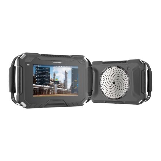
- Page 1 CRY8124 Acoustic Imaging Camera User Manual...
-
Page 2: Table Of Contents
Table of Contents User Notice Introduction Glossary Product and Accessories Product accessory list Battery and charging Product Instruction Appearance Port Power on the camera Power off the camera Sleep Software Function Main interface Interface operation Display interface Scene... - Page 3 Frequency Function settings Photos Custom tools Dropdown menu 6.10 System settings Usage Tips Capturing sound source Eliminating reflection interference Eliminating interference noise Equipment maintenance Contact Us Hangzhou headquarters Dongguan branch Houston Office...
-
Page 4: Revision History
Revision History Revision Description Revision date number 2024/04/19 Initial version 2024/07/19 Add description... -
Page 5: User Notice
Hangzhou CRYSOUND Electronic Co., Ltd. or other authorized companies. Without written permission, no entity or individual may excerpt, reproduce, translate, or modify this manual in any way. Hangzhou CRYSOUND Electronic Co., Ltd. does not provide any express or implied statements or warranties. - Page 6 Please carefully read the content of this safety notice before using the product. Only use the product for its designated purpose. 3. Do not disassemble the device without authorization. 4. If the device experiences any malfunctions or abnormal heating, please stop using 5.
-
Page 7: Introduction
Paired with sophisticated analysis software, CRY8124 assists users in analyzing, editing, and generating reports for audio, video, and image data. -
Page 8: Glossary
Glossary USB power delivery (USB PD) The device utilizes a power delivery protocol based on the USB 3.0 standard, allowing for higher power transfer through the USB port. Sound pressure level (SPL) The device measures the amplitude of the sound source using sound pressure level (SPL), which is a physical quantity that represents the magnitude of a sound wave. -
Page 9: Dynamic Range
When a frequency range is selected within the full frequency range supported by the device, the device will only measure and display a sound cloud image that is within this frequency range. Sound outside this frequency range will not be displayed. Frequency peak A peak in the spectrum denotes a strong sound energy distribution at this frequency. - Page 10 Mechanical scenario Mechanical scenario involves the detection of mechanical anomalies causing ultrasound, such as damaged conveyors. In this scenario, besides time-domain analysis, spectrogram analysis, and viewing of infrared images, multiple frequency points and single frequency points can be set to analyze the tested equipment.
-
Page 11: Product And Accessories
Integrated LED battery indicator, a single charge lasts for 5 hours. Thermal imaging camera IA1301(384*288 resolution), module (optional) IA1302(640*512 resolution), compatible with CRY8124 device. Smart battery charger Charges 1 battery at a time. Lightweight, small size design. Battery and charging Battery information The device is powered by a lithium-ion battery with a nominal capacity of 6600mAh at 7.2V. - Page 12 Use your fingers to pinch the battery tongue and pull it outward to remove the battery. 3. Check the battery level. There are 5 LED battery level indicator lights on the battery (indicating 20%, 40%, 60%, 80%, and 100% battery levels). To check the battery level, press the "PUSH"...
-
Page 13: Product Instruction
Product Instruction Appearance Function button Power button Power indicator Hand Straps Display screen Battery cap light Microphone Array Optical camera... -
Page 14: Port
Port 1 - 3.5mm audio jack During the inspection test, insert a 3.5mm earphone, and you will be able to hear an audio representation of the ultrasonic signal. 2 - SIM card slot Inserting the SIM card and enabling the mobile data function, you can upload data to the platform (supported by some models). -
Page 15: Power On The Camera
After inserting the thermal imaging camera module, the camera can display thermal images. Power on the camera When the battery is sufficiently charged, press and hold the " " button for 5s until the power indicator lights up. After powering on, the camera will enter the testing interface. Note: Before powering on, please ensure that the battery has sufficient charge. - Page 16 Enable auto sleep and set the desired time for auto sleep. 3. Tap " " to save and exit. Note: Short press the " " button to wake up the camera from sleep.
-
Page 17: Software Function
Software Functions Main interface 1 - Fixed buttons Scene, Photos, Frequency, Settings. 2 - Dropdown menu By pulling down the dropdown menu, you can access and customize various functions and open the system settings. 3 - Status bar Displays the current working status of device functional modules. 4 - Time Displays the current time of the camera. -
Page 18: Interface Operation
6 - Chart 1 You can set up PRPD spectrogram, Time domain chart, Thermal image, Time-Frequency domain graph, and camera image. 7 - Chart 2 You can set up PRPD spectrogram, Time domain chart, Thermal image, Time-Frequency domain graph, and camera image. 8 - Chart 3 You can set up PRPD spectrogram, Time domain chart, Thermal image, Time-Frequency domain graph and camera image. -
Page 19: Display Interface
Dragging the thermal image to the left or right area enters the split-screen display mode. Scene By clicking on the "Scene" button, users can select preset scenarios. The CRY8124 camera comes pre-set with four default scenarios, "General Scenario", "Gas Leak Scenario", "Partial discharge scenario", and "Mechanical Scenario". Additionally, users can customize other scenarios. - Page 20 When the camera is operating in the "General scenario", it can capture gas leaks, partial discharge, and other noise signals. It can also display the source location on the screen but does not have analysis capabilities. On the main interface, clicking on "Function Settings" will take you to the function parameter settings page.
- Page 21 Users can choose from five types: Connector, Flange, Weld, Thread, and Hole, to match the corresponding leakage point type for more accurate leakage volume testing. On the main interface, clicking on "Function Settings" will take you to the function parameter settings page. In the "Acoustic Parameter" section, select "Gas". Gas type Same as the gas type on the main interface.
- Page 22 When the camera is operating in the "Partial discharge scenario", it can capture partial discharge signals and display the source location on the screen. It also has PRPD analysis capabilities. After clicking on the icon in the top right corner of the graph, you can select the PRPD graph display.
-
Page 23: Frequency
After clicking on "Freq.", you can choose between multiple frequency points or a single frequency point. When selecting multiple frequency points, the right side of the main interface will display five frequency checkboxes. Clicking on "40kHz" can activate/deactivate the 40kHz frequency point (up to four frequency points can be deactivated). - Page 24 Acoustic pallete Sets the color scheme for the sound cloud image in the detection screen. Users can choose from options such as rainbow color, iron red, or iron gray. Dynamic range When imaging points are greater than 1, increasing the dynamic range allows for the detection of sound sources with varying sound pressures.
- Page 25 Note: Please keep in mind that some glossary related to specific devices or software may vary, and the translation provided here is a general representation of the acoustic parameter settings. Thermal parameter settings Thermal palette Allows selection of the thermal imaging color palette, such as rainbow color, white-hot, black-hot, iron red, iron gray, or high-resolution rainbow.
-
Page 26: Photos
Thermal correction Allows adjustment of temperature correction for the thermal module. Ambient temperature Allows input of the ambient temperature during measurements. Background Temperature Allows input of the background or reflected temperature during measurements. Note: Please note that the available options and glossaries may vary depending on the specific infrared device or software being used. -
Page 27: Custom Tools
Click "Select" to enter multi-selection mode. Users can choose multiple photos and videos, then click the " " button to remove them. Click on an image to enter the image viewing interface. Tap the screen to reveal the photo's name and tag button. Image favoriting Click "... -
Page 28: Dropdown Menu
Click " " next to the tool under "Show on navigation bar" to remove the corresponding tool. In the "More" section, select the tools you want to add. Click the " " button next to the tool parameter on the left to add it to the toolbar. 3. -
Page 29: Hotspot Settings
After entering the system settings interface, navigate to the Bluetooth® settings. The camera's Bluetooth name is CRY8124. Users can connect devices with Bluetooth using the following steps: 1. Click the " " button to turn Bluetooth on or off. 2. Click "... -
Page 30: Date And Time
In brightness, you can adjust the brightness of the current display (0% to 100%). 3. Click the " " button to turn on automatic brightness, which adjusts the brightness according to ambient light. 4. Click " " to save and exit. Date and time Clicking "Date and time"... -
Page 31: Restore Factory Setting
1. Download the firmware to your PC. 2. Place the firmware in the "Update" folder in the TF card, or connect the device to your PC via USB-C cable, open the "CRY8124" disk, and place the firmware in the "Update" folder. -
Page 32: Microphone Test
Users can view the user manual following these steps: Clicking " " on the right side of the user manual will take you to the user manual preview interface, where you can view the electronic version of the user manual. Clicking "... -
Page 33: Usage Tips
Usage tips Capturing sound source Observe the frequency spectrum graph for any prominent signals or peaks. If such signals exist, adjust the frequency band to encompass the frequency range where the prominent signal or peak is located. Then, observe if any sound sources appear in the display. -
Page 34: Contact Us
Contact us Hangzhou headquarters Tel: +0086-0571-88225198, +0086-0571-88225128 E-mail: info@crysound.com Add: No.10, Xianqiao Road, Zhongtai Street, Yuhang District, Hangzhou, Zhejiang Province, China Web: www.crysound.com Dongguan branch Tel: +0086-0769-21688120 E-mail: info@crysound.com Add: 7F, B1 Bldg, Songhu Lake, Intelligent Valley, Liaobu Town, Minfu Rd, Donguan City, Guangdong Province, China Web: www.crysound.com...
Need help?
Do you have a question about the CRY8124 and is the answer not in the manual?
Questions and answers