
Summary of Contents for INVT EVC16-AW7KGF1U2
-
Page 1: Home Smart Ac Ev Charger
Home Smart AC EV Charger EVC16-AW7K/11K/22KGF1U2 (UC) Installation and Operation Manual V1.1... -
Page 2: Table Of Contents
CONTENTS Home Smart AC EV Charger ················································································································································ 1 1 About This Manual ···························································································································································3 1.1 Conventions ····································································································································································3 1.2 Document Accuracy ······················································································································································· 4 1.3 Applicable Group & Area ··············································································································································· 4 1.4 How To Use This Manual ················································································································································4 1.5 Symbols, Abbreviations, and Terms ······························································································································· 4 1.6 General Documents ························································································································································6 2 SAFETY INSTRUCTIONS ····················································································································································... -
Page 3: About This Manual
About This Manual This manual provides instructions for installing, utilizing, and routine fault diagnosis & troubleshooting of INVT 7 kW, 11kW, and 22kW AC Smart EV Charger Home. Before installing the charger, please read this manual to familiarize yourself with the instructions and ensure a successful installation and smooth operation. -
Page 4: Document Accuracy
This manual contains information about one or more INVT products and may include descriptions or references to one or more standards for INVT products. The presence of any such standard description does not imply that all INVT products referenced in this document support that standard or all described functionalities All information, specifications, and illustrations in this manual are based on the latest information available at the time of printing. - Page 5 Tools required to perform the installation procedures. Ensure the charger is powered off before performing the procedures of this manual The operator needs to have professional knowledge of electricity or qualifications according to the requirement of local criteria. Note: The manual may not demonstrate all the symbols or terms of the charger, but it does not affect your understanding of this manual.
-
Page 6: General Documents
2.3 Save These Instructions The safety messages herein cover situations INVT is aware of. INVT cannot know, evaluate, or advise you as to all of the possible hazards. You must be certain that any condition or service procedure encountered does not jeopardize your personal safety. - Page 7 IMPORTANT: 1. This charger must be installed by a licensed electrician. 2. INVT is not responsible for the following conditions: -- Failure to adhere to the above-mentioned safety instructions. -- Any damage caused by failure to follow relevant procedures for equipment installation or other operations.
-
Page 8: Product Disposal
Product Description EVC16-AW7K/911K/22KGF1U2 (UC) is an intelligent charger series launched by INVT for European areas and other areas than comply with IEC standard, which is designed to charge a plug-in hybrid electric vehicle or an electric vehicle. Our charger provides a reliable, fast, safe, and smart charging solution for individual home users. -
Page 9: Led Indicator Descriptions
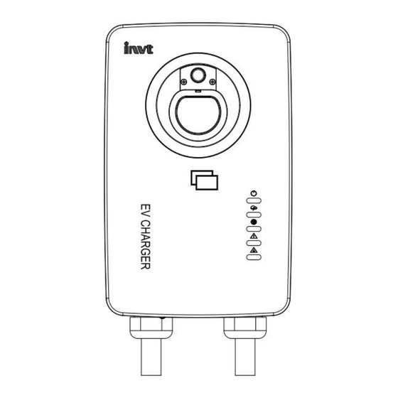
1.Connector Release Button 2.Charging Connector Holder 3.Charger Enclosure Name 4.Bottom AC cable Inlet Hole 5.USB Port for Software Upgrade and 4G Card Inlet(Reserved) 6.Emergency Stop Button 7.Circular Breathing LED 8.LED Indicator( Top to bottom ) ● Power LED ● Charging LED ●... -
Page 10: Specifications
If higher altitude 6561ft Altitude operation is required, please 2000m contact local dealer or manufacturer further assistance. Electrical Parameters Product Information EVC16-AW7KGF1U2(UC) EVC16-AW11KGF1U2(UC) EVC16-AW22KGF1U2(UC) Charging Mode Mode 3 230Vac±15% Input/Output Voltage 400Vac±15% (L1,L2,L3,N,PE),50/60 Hz (L,N,PE), 50/60 Hz... - Page 11 Protection Over current, Over voltage, Under voltage, Ground fault detection User Interface User Authentication INVT RFID Card (2 included) or INVT EV Charger App User Interface INVT Charge App Communication OCPP1.6J (Customization) Protocol Connectivity WIFI / Bluetooth Status Indication 5 LEDs + 1 Charging breath circular LED...
-
Page 12: Product Nameplate
3.5 Product Nameplate Manufacturer Logo Charger Model Charger Input Parameters Charger Rated Frequency Charger Output Voltage Charger Output Current Working Ambient Temperature Charger IP Rating Series Number and Execution Standard Production Date Charger Compliance Mark Manufacture Name NOTE: The image data is for reference only; please refer to the actual nameplate on the charger. -
Page 13: General Installation Procedure
4.2 General Installation Procedure Preparing location before installation. For detailed information, please refer to Chapter 4.3. Unpacking the packaging. For detailed information, please refer to Chapter 4.4. Carry out installation. For detailed information, please refer to Chapter 5. Powering on and off the charger. For detailed information, please refer to Chapter 6. 4.3 Ambient and Tool Requirements Before installation, please prepare: Clear an appropriate site for installation. -
Page 14: Installation
Screwdriver (Type T10) Screwdriver (Type T25) NOTE: The list may not necessarily include all the tools required for installation. We recommend you read through the installation procedure and gather all the tools needed prior to installation. Installation 5.1 General Electrical Regulation Before operating the electrical installation, ensure you have understand the following electrical rules of the charger, there are two models of AC power input connectors, single phase and three phase, the pictures are as follows:... -
Page 15: Hardwired Installation
For the charger models: EVC 16-AW11KGP1U2(UC) and EVC 16-AW22KGP1U2(UC), they are suitable for 400 (380) Vac three-phase AC power input: Wiring Terminal Definition General Requirement Note: 1. For EVC 16-AW11KGP1U2(UC) charger, the maximum continuous working current is 16A, and the cable should meet the above requirements. - Page 16 Remove the maintaining plate from the charger by removing the screws using a screw driver and the power input connector can be visible. Put the power cable (10AWG Max) through the input port and connect it to the L1(L2,L3)N, and PE connector. Tighten each connectors screw with a maximum2 N·m (17.7 in·lbs).
- Page 17 pretreat the cable(If possible, crimp the cable to a tubular terminal for subsequent connection) for preparation. 2) Remove the front plate maintenance cover 3) Remove the maintenance cover screws using a screwdriver, and you can see the terminal connect to the AC cable and the power distribution module.
-
Page 18: Location And Position
Note: 1. In addition to identify the AC input cable connection by above pictures,engineers can also distinguish the wiring by the print on the terminal row. 2. Before connecting the AC input cable to the power grid network, please complete the mechanical installation of the charger first in order to ensure safety. - Page 19 Specific technical data: parameter Recommended Specification (mm) ≥300 B(Indoor installation) ≥900 B (Outdoor installation) ≥1300 Note: The range of installation size can be selected according to local regulatory requirements or actual installation conditions of the location. DANGER: Risk of shock. Turn off the power to the outlet at the circuit breaker until the installation is completed. Install the rear plate and the charger Remove the charger rear plate from the accessories bag.
-
Page 20: Connecting The Ethernet Cable
Install the charger to the rear plate according to the location of the mounting holes. Tighten the bottom screws of the charger. 5.4 Connecting the Ethernet Cable Loosen the protective cover of the charger's LAN port to access the LAN connector. Put the Ethernet cable with the RJ45 plug to the LAN port for the LAN/Internet access preparation. -
Page 21: Rs485 Cables Wiring (Optional)
5.5 RS485 Cables Wiring (Optional) This communication port is solely intended to connect the charger and Power Distribution Module/DLB module(sold separately). If your charger does not come with the module, please ignore the description in this section. Loosen the terminal cover at the back or the bottom of the device and use a tool to punch through the wire holes. -
Page 22: Operation
You may need to add the charger through your mobile devices: Please scan the QR code below, or simply search for “INVT Charge” on Google Play or the App Store to download our App to your mobile device. (Note: APP name is “INVT Charge”, not “INVT EV Charge” ) Open our EV Charging app on your mobile device, and log in with your email or phone number. -
Page 23: Binding Rfid Card Via App
Scan the charger’s barcode and the QR code below, you can also find it on the charger’s nameplate, to add the charger. IMPORTANT: To add a charger, please ensure that the charger is already connected to the Internet or Bluetooth is enabled on your mobile device. -
Page 24: Ending Charging
3) Choose one of the following charging methods to start a charging session: -- Tap 'Start' on the charging interface of the charging App. If the Auto Start function(Plug and Play) is enabled in the charging App, the charger will automatically start charging once the connector is properly connected. - Page 25 Item Faults Solutions Make sure the circuit breaker or other power switch has been Power input failure/no voltage. turned on. 1. Do not insert the charging interface into your EV charging port The charge session does not before setting up a charging schedule for the first time. start as scheduled.
-
Page 26: Regulations Compliance
Check whether Bluetooth is enabled on your mobile device and whether the charger is powered on and working successfully. Check whether the charger is in the Bluetooth settings on Bluetooth connection failed your mobile device and pair the charger to your device via Bluetooth again. -
Page 27: Radiation Frequency (Rf) Exposure
Charger fault information or code( View through the App). The damaged or malfunctioning equipment. INVT provides complete technical support to our customers. Customers can reach us through the local offices or dealer representatives. Or contact our technical support directly. Contact information: Website: www.invt-ev.com...
Need help?
Do you have a question about the EVC16-AW7KGF1U2 and is the answer not in the manual?
Questions and answers