
Summary of Contents for Mass Flow ONLINE MAG-VIEW MVM-P Series
- Page 1 User's Guide Magnetic Inductive Flow Meter MAG-VIEW™ Series MVM‑P Please keep this operating manual for future reference. If the device is resold, please provide the operating manual along with it.
-
Page 2: Table Of Contents
MVM‑P Table of contents page About this operating manual..................3 Safety instructions ..................... 4 Device description ..................... 6 Construction and function..................7 Installation of MVM‑P ....................8 4.1 Installation instructions .................... 8 4.2 Mounting ......................... 9 Electrical connection ....................10 5.1 Wirings ........................ -
Page 3: About This Operating Manual
MVM‑P About this operating manual About this operating manual Symbols used: WARNING Failure to do so may result in death or serious injury CAUTION Failure to do so may result in minor or moderate injury. IMPORTANT Failure to do so may result in damage to property and the environment. If you have any problems or questions, please contact your supplier or contact us directly at: Exclusion of liability We accept no liability for any damage or malfunctions resulting from incorrect installation, inappropri-... -
Page 4: Safety Instructions
In order to guarantee that the device operates safely, the operator must act competently and be conscious of safety issues. MASS FLOW ONLINE B.V. provides support for the use of its products either personally or via relevant literature. The customer verifies that our product is fit for purpose based on our technical information. - Page 5 MVM‑P Safety instructions Qualified personnel The personnel who are charged for the installation, operation and maintenance of the • MVM‑P must hold a relevant qualification. This can be based on training or relevant tui- tion. The personnel must be aware of this operating manual and have access to it at all times. •...
-
Page 6: Device Description
Device description MVM‑P Device description The MVM‑P series from MASS FLOW ONLINE B.V. is a flow sensor without moving parts. The measurement is performed using magnetic induction. The MVM‑P is used for measuring or metering water and electrically conductive fluids. The compact design and independence from the intake and discharge sections allows the MVM‑P... -
Page 7: Construction And Function
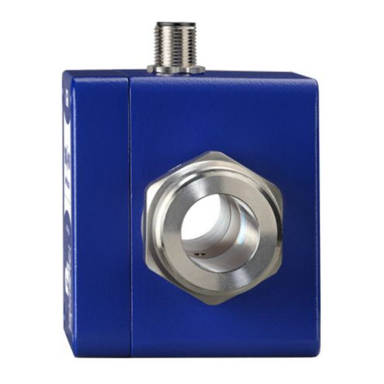
MVM‑P Construction and function Construction and function Components Housing. Electrical connection: The electrical connection is made via 5-pin plug M12x1. Operation / flow indicator LED. Process connection: The process connections are available in different sizes. Type plate (sticker). -
Page 8: Installation Of Mvm-P
Installation of MVM‑P MVM‑P 4 Installation of MVM‑P Before installing, check that the wetted materials of the device are suitable for the liquid being used ( § 9.2 "Materials table"). the equipment is switched off and is in a safe and de-energised state. ... -
Page 9: Mounting
MVM‑P Installation of MVM‑P Installation can occur in horizontal and vertical pipes. The flow sensor is only suitable for • application in completely filled pipe systems. As a matter of principle magnetic inductive flow sensors are widely independent from the •... -
Page 10: Electrical Connection
Connecting cable Suitable connection cables with moulded coupling socket are available included in the range of MASS FLOW ONLINE B.V. accessories. The shielding is already connected with the knurled nut. The maximum length of the connecting cable is 30 m. - Page 11 MVM‑P Electrical connection IMPORTANT Pay attention to the temperature resistance of the connecting cable ( § 9 "Technical data") at high media temperatures. If the temperature resistance is smaller than the medium temperature, the cable may not be directly laid on the pipe. Connection 5-pin plug M12x1 ...
-
Page 12: Wirings
Electrical connection MVM‑P 5.1 Wirings Pinout The pinout differs according to the chosen configuration of the device. Possible pinout: Pin 1: +U Pin 2: d. n. c. (do not connect) / Analogue U/I Pin 3: GND Pin 4: Frequency Pin 5: n. c. (not connected) M12x1 ... -
Page 13: Commissioning And Measuring Mode
MVM‑P Commissioning and measuring mode 6 Commissioning and measuring mode Before switching on the MVM‑P for the first time, please follow the instructions in the follow- ing section. 6.1 Commissioning Check that the MVM‑P has been installed correctly and that all screw connections are sealed. ... -
Page 14: Maintenance And Cleaning
Maintenance and cleaning MVM‑P MVM‑P with analogue output According to the configuration of the MVM‑P, the analogue output provides a voltage or current signal. This signal is proportional to the measured flow. Maintenance and cleaning Maintenance The MVM‑P is maintenance-free and cannot be repaired by the user. In case of a defect, the device must be replaced or sent back the manufacturer for repair. -
Page 15: Disassembly And Disposal
MVM‑P Disassembly and disposal 8 Disassembly and disposal CAUTION Never remove the device from a plant in operation. Make sure that the plant is shut down professionally. Before disassembly Prior to disassembly, ensure that the equipment is switched off and is in a safe and de-energised state. ... -
Page 16: Technical Data
Technical data MVM‑P Technical data The technical data of customised versions may differ from the data in these instructions. Please observe the information specified on the type plate. 9.1 Characteristics MVM‑P Type MVM-001 MVM-030 MVM-060 MVM-250 MVM-002 Measurement device characteristics Measuring range 0.0083...1 l/min •... -
Page 17: Materials Table
MVM‑P Technical data MVM-001 MVM-030 MVM-060 MVM-250 Type MVM-002 Electrical characteristics Supply voltage 12...24 VDC (±10 %) 24 VDC (±10%) Current consumption ≤ 150 mA Electrical connection 5-pin-plug M12x1 Degree of protection IP 65 and IP67 (with MFO.CB.25) (EN 60529) Process variables Medium to measure: Water and other conductive liquids... -
Page 18: Pressure Drop
Technical data MVM‑P 9.3 Pressure drop Typical pressure drop MVM-001 / MVM-002 Typical pressure drop MVM-030 VMI07 VMI10 Flow rate Q [l/min] Flow rate Q [l/min] Typical pressure drop MVM-060 Typical pressure drop MVM-250 Flow rate Q [l/min] Flow rate Q [l/min] 9.4 Temperature limits The maximum ambient temperature depends on the medium temperature and the version of the MVM‑P. -
Page 19: Dimensions
MVM‑P Technical data 9.5 Dimensions ⎔ Dimensions from drawing in mm ⌀3 MVM- L1 ±0,5 L2 ±0,5 001 / G ¼ A ⌀10 ⌀10 G ½ A ⌀20 G ¾ A G 1 A 33.5 Technical changes reserved - 19 -... - Page 20 MVM‑P - 20 - MassFlowONLINE_MVM 03/2021...
Need help?
Do you have a question about the MAG-VIEW MVM-P Series and is the answer not in the manual?
Questions and answers