Table of Contents
Advertisement
Available languages
Available languages
Quick Links
KOBALT and logo design are trademarks or registered
trademarks of LF, LLC. All rights reserved.
Serial Number
Purchase Date
Thank you for purchasing this KOBALT product.
Questions, problems or missing parts?
Before returning, contact us on:
888-356-2258, 8 a.m. - 8 p.m., EST, Monday - Sunday or ascs@lowes.com.
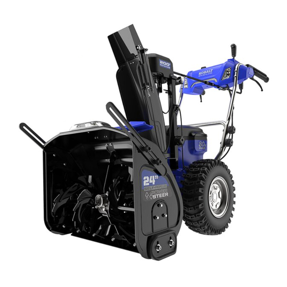
SG24408
80V SNOW
THROWER
ATTACH YOUR RECEIPT HERE
1
ITEM #5974893
MODEL #KDSB 5280-06
Español p. 33
Advertisement
Table of Contents

Summary of Contents for LF KOBALT KDSB 5280-06
- Page 1 ITEM #5974893 MODEL #KDSB 5280-06 80V SNOW KOBALT and logo design are trademarks or registered trademarks of LF, LLC. All rights reserved. THROWER Español p. 33 ATTACH YOUR RECEIPT HERE Serial Number Purchase Date Thank you for purchasing this KOBALT product.
-
Page 2: Table Of Contents
TABLE OF CONTENTS Product Specifications..........................Package Contents..........................Hardware Contents..........................Symbols..............................Safety Information..........................Preparation............................. Assembly Instructions..........................Operating Instructions..........................Care and Maintenance ......................... Transportation and Storage........................Troubleshooting............................. Warranty..............................Replacement Parts List......................... PRODUCT SPECIFICATIONS SPECIFICATIONS Battery type 80 V Lithium-ion Clearing width 24 in. Intake height 18 in. -
Page 3: Package Contents
PACKAGE CONTENTS PART DESCRIPTION QUANTITY PART DESCRIPTION QUANTITY Self-propelled drive paddle Drift cutter Intake housing Chute deflector control Auger lever Scraper plate Led headlight Skid shoe Discharge chute control Wheel Chute deflector Battery compartment Discharge chute Lower handle 3-in-1 cleanout tool Upper handle... - Page 4 PACKAGE CONTENTS HOLD PART DESCRIPTION QUANTITY PART DESCRIPTION QUANTITY ON button Self-propelled drive paddle Left zero turn trigger Chute deflector control lever Right zero turn trigger Self-propelled drive speed control switch Battery indicator Led headlight button LED headlight button Auger speed control switch Discharge chute adjustment handle Auger engagement paddle...
-
Page 5: Hardware Contents
HARDWARE CONTENTS (not to scale) Cup head square Saddle Type Handle knob Cup head square neck neck bolt with large Elastic Washer bolt head Qty. 5 (M8*55 Bolt) (M8*55 Bolt) Qty. 4 Qty. 4 Qty. 1 Pin shaft M6*25 Bolt Qty. - Page 6 HARDWARE CONTENTS (not to scale) Prevailing torque type M6 Nut Plain washer hexagon thin nuts (with non-metallic insert) Safety pin Qty. 2 Qty. 5 (M8 Nut) Qty. 2 Qty. 5 Fastening M8*25 Bolt M6*18 Bolt knob Qty. 4 Qty. 8 Qty.
-
Page 7: Symbols
SYMBOLS SYMBOLS EXPLANATION Direct current Precautions that involve your safety. Read and understand all instructions before operating the product, and follow all warnings and safety instructions. Keep hands away from the discharge area. Keep feet out of impeller. Keep feet away from rotating impeller. -
Page 8: Safety Information
SAFETY INFORMATION The following signal words and meanings are intended to explain the levels of risk associated with this product. SYMBOL SIGNAL MEANING Indicates an imminently hazardous situation, which, if not DANGER avoided, will result in death or serious injury. Indicates a potentially hazardous situation, which, if not avoided, WARNING could result in death or serious injury. - Page 9 SAFETY INFORMATION This snow thrower is capable of amputating hands and feet and throwing objects. Failure to observe the following safety instructions could result in serious injury. WARNING Read all safety warnings and instructions. Failure to follow the warnings and instructions may result in electric shock, fire and/or serious injury.
- Page 10 SAFETY INFORMATION • Operation of the snow thrower in the hand-held position is unsafe, except in accordance with the special instructions for such use provided in the operator’s manual. • Keep hands away from moving parts. • Keep guards in place and in working order. •...
- Page 11 SAFETY INFORMATION 5. OPERATION • Do not put hands or feet near or under rotating parts. Keep clear of the discharge opening at all times. • Exercise extreme caution when operating on or crossing gravel drives, walks, or roads. Stay alert for hidden hazards or traffic.
-
Page 12: Preparation
SAFETY INFORMATION 6. MAINTENANCE AND STORAGE • Check shear bolts and other bolts at frequent intervals for proper tightness to be sure the equipment is in safe working condition. • Always refer to owner’s guide instructions for important details if the snow thrower is to be stored for an extended period. -
Page 13: Assembly Instructions
ASSEMBLY INSTRUCTIONS 1a. Installing the upper handle • Align the holes in the middle handle and the upper handle. 1b. Installing the upper handle • Insert the bolt through the middle handle and upper handle. • Tighten the handle knob (AA) and the washer (BB) onto the bolt (CC). - Page 14 ASSEMBLY INSTRUCTIONS 2a. Installing the discharge chute • Loosen the knob and bolt on the discharge chute assembly. • Align the holes on the discharge chute with the holes on the lower support. • Once you have engaged the discharge chute onto the chute base, push until you hear a click.
- Page 15 ASSEMBLY INSTRUCTIONS 3a. Installing the chute control rod • Make sure that the discharge chute faces forward. • Keep the grip handle up. • Push the discharge chute control rod (D) through the slot (FF) below the control panel. • Put the end of the discharge chute control rod (D) straight through the hole of the chute support (II).
- Page 16 ASSEMBLY INSTRUCTIONS 4. Installing the battery pack • Open the battery door. • Align the lift ribs on the battery pack with the grooves in the battery compartment. • Push the battery pack into the battery compartment until the battery pack locks into place.
-
Page 17: Operating Instructions
OPERATING INSTRUCTIONS 1. Know your product FUNCTION This product allows self-propelled drive mode that it can walk itself. Self- propelled drive mode brings you easy operation. Turn assist handles for quick and effortless steering. This product is equipped with zero turn system, which gives the product accurate and smooth steering without deviation. - Page 18 OPERATING INSTRUCTIONS 2. Starting and stopping the auger and impeller To start auger/impeller: • Push the ON button (U). • Depress and hold the auger engagement paddle (T). To stop auger/impeller: • Release the auger engagement paddle (T). NOTE: Lower the scraper to the ground to remove the snow.
- Page 19 OPERATING INSTRUCTIONS 4. Self-propelled drive mode To start drive system: • Push the ON button (U). • Depress and hold the drive paddle (A). • To increase the drive speed, push the self-propelled drive speed control switch (Q) forwards. • To decrease the drive speed, pull the self-propelled drive speed control switch (Q) backwards.
- Page 20 OPERATING INSTRUCTIONS 6. Lock self-propelled drive paddle and auger engagement paddle with one hand • When you push the self-propelled drive paddle (A) and the auger engagement paddle (T) at the same time, the auger engagement paddle will be temporarily locked. •...
- Page 21 OPERATING INSTRUCTIONS 8a. Adjusting the discharge chute NOTE: You can adjust the discharge chute 200° to change the snow direction. 100° 100° 8b. Adjusting the discharge chute • Pull back the discharge chute adjustment han- dle (Z) for a short distance. 8c.
- Page 22 OPERATING INSTRUCTIONS 8d. Adjusting the discharge chute • Rotate the discharge chute adjustment handle (Z) left to move the discharge chute (F) to the left. Release the grip handle to lock the chute in the desired direction. • Rotate the discharge chute adjustment handle (Z) right to move the discharge chute (F) to the right.
- Page 23 OPERATING INSTRUCTIONS 9b. Adjusting the chute deflector • Move the chute deflector control lever (B) for- ward to adjust the chute deflector (E) down and decrease the snow throw distance. • Move the chute deflector control lever (B) back- ward to adjust the chute deflector (E) up and increase the snow throw distance.
-
Page 24: Care And Maintenance
CARE AND MAINTENANCE WARNING Remove the safety key and battery pack from the product before maintenance. CAUTION Use only approved replacement parts. Do not let brake fluids, gasoline, petroleum-based materials touch the plastic parts. Chemicals can cause damage to the plastic, and make the plastic unserviceable. Do not use strong solvents or detergents on the plastic housing or components. - Page 25 CARE AND MAINTENANCE 3. Replacing the skid shoes NOTE:The range of adjustable height for skid shoes is 1.5mm, when putting the bolts through the U-hole on the skid shoes. • Loosen the 2 sets of bolts (OO), washers (PP) and nuts (QQ) that attach the skid shoe (L) to the snow thrower housing.
- Page 26 CARE AND MAINTENANCE 5a. Replacing the safety pin NOTE: The safety pin is used to disperse the pressure of snow to protect the auger/impeller bar (UU). • Remove the nuts (WW) and safety pins (XX). Hardware Used M6 Nut Safety pin 5b.
- Page 27 CARE AND MAINTENANCE 6a. Replacing the drift cutter • Remove the batteries. • Insert the two bolts (XX) into the intake hous- ing wall. • Install the drift cutter (H) and wing nuts (YY) onto the bolts. Hardware Used M8*25 Bolt Fastening knob 6b.
-
Page 28: Transportation And Storage
TRANSPORTATION AND STORAGE 1a. Moving the product manually WARNING When the pushing resistance of the whole product becomes large or cannot be pushed, the user needs to check whether the unilateral wheel can be turned by hand when it is off the ground. If it can't be rotated easily, you need to disassemble the chassis bottom plate and unplug the motor cable. -
Page 29: Troubleshooting
TROUBLESHOOTING PROBLEM POSSIBLE CAUSE SOLUTION Adjust the height of the handle and make The handle is not in The bolts are not engaged sure that the knobs and bolts are aligned position. correctly. correctly. Charge the battery by following the The battery is not charged. -
Page 30: Year Limited Warranty
WARRANTY 5-YEAR LIMITED WARRANTY This KOBALT snow thrower is warranted to the original purchaser from the original purchase date for five (5) years subject to the warranty coverage described herein. This KOBALT snow thrower is warranted for the original user to be free from defects in material and workmanship. -
Page 31: Replacement Parts List
REPLACEMENT PARTS LIST For replacement parts, call our customer service department at 888-356-2258, 8 a.m. - 8 p.m., EST, Monday - Sunday. You could also contact us at ascs@lowes.com. PART DESCRIPTION PART # Discharge chute assembly R0203398-00 Discharge chute control rod assembly R0209493-00 VV, WW Safety pin kit... - Page 32 REPLACEMENT PARTS LIST For replacement parts, call our customer service department at 888-356-2258, 8 a.m. - 8 p.m., EST, Monday - Sunday. You could also contact us at ascs@lowes.com. PART DESCRIPTION PART # H, XX, YY Drift cutter kit R0209496-00 3-in-1 cleanout tool R0209495-00 AA, DD...
- Page 33 ARTÍCULO #5974893 MODELO #KDSB 5280-06 QUITANIEVE DE KOBALT y el diseño del logotipo son marcas comerciales o marcas registradas de LF, LLC. 80 V Todos los derechos reservados. ADJUNTE SU RECIBO AQUÍ Número de serie Fecha de compra Gracias por comprar este producto KOBALT.
-
Page 34: Especificaciones Del Producto
ÍNDICE Especificaciones del produto........................Contenido del paquete..........................Aditamentos............................Símbolos..............................Información de seguridad........................Preparación............................Instrucciones de ensamblaje........................Instrucciones de funcionamiento......................Cuidado y mantenimiento ........................Transporte y almacenamiento........................Solución de problemas..........................Garantía..............................Lista de piezas de repuesto........................ESPECIFICACIONES DEL PRODUCTO ESPECIFICACIONES Tipo de batería Iones de litio de 80 V Ancho de eliminación 60.96 cm... - Page 35 CONTENIDO DEL PAQUETE PIEZA DESCRIPCIÓN CANTIDAD PIEZA DESCRIPCIÓN CANTIDAD Paleta de tracción Despejador autopropulsada Carcasa de entrada Palanca de control del Barrena deflector del conducto Placa raspadora Faro LED Zapata Varilla de control del Rueda conducto de descarga Compartimiento de la Deflector del conducto batería Conducto de descarga...
- Page 36 CONTENIDO DEL PAQUETE HOLD PIEZA DESCRIPCIÓN CANTIDAD Paleta de tracción autopropulsada PIEZA DESCRIPCIÓN CANTIDAD Palanca de control del Botón de encendido deflector del conducto Gatillo de giro cero a la Interruptor de control de izquierda velocidad de la tracción autopropulsada Gatillo de giro cero a la derecha Botón del faro LED...
- Page 37 ADITAMENTOS (no se muestran a escala) Perno de cuello Arandela elástica Perilla de la Perno de cuello cuadrado con tapa tipo saddle manija cuadrado con tapa y cabeza grande (Perno M8*55) (Perno M8*55) Cant. 5 Cant. 4 Cant. 4 Cant. 1 Eje del Pasador Perno M6*25...
- Page 38 ADITAMENTOS (no se muestran a escala) Tuercas hexagonales Tuerca M6 Arandela lisa delgadas de torque sobresaliente (con inserto Pasador de Cant. 2 Cant. 5 seguridad no metálico) (Tuerca M8) Cant. 2 Cant. 5 Perilla de Perno M8*25 Perno M6*18 sujeción Cant.
- Page 39 SÍMBOLOS SÍMBOLOS EXPLICACIÓN Corriente directa Precauciones que involucran su seguridad. Lea y comprenda todas las instrucciones antes de utilizar el producto y siga todas las advertencias e instrucciones de seguridad. Mantenga las manos alejadas del área de descarga. Mantenga los pies alejados del impulsor. Mantenga los pies alejados del impulsor giratorio.
-
Page 40: Información De Seguridad
INFORMACIÓN DE SEGURIDAD Se usan las siguientes indicaciones y sus significados para explicar los niveles de riesgo asociados a este producto. SÍMBOLO INDICACIÓN SIGNIFICADO Indica una situación de peligro inminente que, de no evitarse, PELIGRO ocasionará la muerte o lesiones graves. Indica una situación potencialmente peligrosa que, de no ADVERTENCIA evitarse, puede resultar en la muerte o en lesiones graves. - Page 41 INFORMACIÓN DE SEGURIDAD Este quitanieve puede amputar extremidades y arrojar objetos. El incumplimiento de las siguientes instrucciones de seguridad podría provocar lesiones graves. ADVERTENCIA Lea todas las advertencias de seguridad y las instrucciones. El incumplimiento de las advertencias y las instrucciones, o declaraciones igualmente definitivas, podría provocar descargas eléctricas, incendios o lesiones graves.
- Page 42 INFORMACIÓN DE SEGURIDAD • El funcionamiento del quitanieve en la posición manual no es seguro, excepto de acuerdo con las instrucciones de uso para dicha posición en el manual del operador. • Mantenga las manos alejadas de las piezas móviles. •...
- Page 43 INFORMACIÓN DE SEGURIDAD 5. FUNCIONAMIENTO • No ponga las manos ni los pies cerca o debajo de piezas rotatorias. Manténgase alejado de la abertura de descarga en todo momento. • Tenga mucho cuidado cuando use la herramienta en entradas, aceras o carreteras con gravilla o cuando tenga que cruzar por ellas.
- Page 44 INFORMACIÓN DE SEGURIDAD 6. MANTENIMIENTO Y ALMACENAJE • Revise los pernos de seguridad y otros pernos de forma periódica para asegurarse de que el equipo se encuentre en buenas condiciones de funcionamiento. • Si debe almacenar el quitanieve durante un período prolongado, siempre consulte las instrucciones del manual del propietario para conocer detalles importantes.
-
Page 45: Instrucciones De Ensamblaje
INSTRUCCIONES DE ENSAMBLAJE 1a. Instalación de la manija superior • Alinee los orificios de la manija central y la manija superior. 1b. Instalación de la manija superior • Inserte el perno a través de la manija central y la manija superior. •... - Page 46 INSTRUCCIONES DE ENSAMBLAJE 2a. Instalación del conducto de descarga • Afloje la perilla y el perno en el conjunto del conducto de descarga. • Alinee los orificios del conducto de descarga con los orificios del soporte inferior. • Una vez que haya enganchado el conducto de descarga en la base del conducto, empuje hasta escuchar un clic.
- Page 47 INSTRUCCIONES DE ENSAMBLAJE 3a. Instalación de la varilla de control del conducto • Asegúrese de que el conducto de descarga mire hacia delante. • Mantenga la manija de agarre hacia arriba. • Empuje la varilla de control del conducto de descarga (D) a través de la ranura (FF) debajo del panel de control.
- Page 48 INSTRUCCIONES DE ENSAMBLAJE 4. Instalación del paquete de baterías • Abra la tapa de las baterías. • Alinee las secciones de elevación en el paquete de baterías con las ranuras en el compartimiento de la batería. • Empuje el paquete de baterías en el compartimiento de la batería hasta que el paquete de baterías encaje en su lugar.
-
Page 49: Instrucciones De Funcionamiento
INSTRUCCIONES DE FUNCIONAMIENTO 1. Conozca su producto FUNCIÓN Este producto permite el modo de tracción autopropulsada en el que puede avanzar solo. El modo de tracción autopropulsada le ofrece un funcionamiento sencillo. Gire las manijas de asistencia para maniobrar de forma rápida y sin esfuerzo. Este producto está... - Page 50 INSTRUCCIONES DE FUNCIONAMIENTO 2. Arranque y detención de la barrena y el impulsor Para poner en marcha la barrena/impulsor: • Presione el botón de encendido (U). • Mantenga presionada la paleta de accionamiento de la barrena (T). Para detener la barrena/impulsor: •...
- Page 51 INSTRUCCIONES DE FUNCIONAMIENTO 4. Modo de tracción autopropulsada Para iniciar el sistema de tracción: • Presione el botón de encendido (U). • Mantenga presionada la paleta de tracción (A). • Para aumentar la velocidad de tracción, empuje el interruptor de control de velocidad de tracción autopropulsada (Q) hacia delante.
- Page 52 INSTRUCCIONES DE FUNCIONAMIENTO 6. Bloquee la paleta de tracción autopropulsada y la paleta de accionamiento de la barrena con una mano • Cuando empuje la paleta de tracción autopropulsada (A) y la paleta de accionamiento de la barrena (T) al mismo tiempo, la paleta de accionamiento de la barrena se bloqueará...
- Page 53 INSTRUCCIONES DE FUNCIONAMIENTO 8a. Ajuste del conducto de descarga NOTA: puede ajustar el conducto de descarga en 200° para cambiar la dirección de la nieve. 100° 100° 8b. Ajuste del conducto de descarga • Jale la manija de ajuste del conducto de descarga (Z) hacia atrás para una distancia corta.
- Page 54 INSTRUCCIONES DE FUNCIONAMIENTO 8d. Ajuste del conducto de descarga • Gire la manija de ajuste del conducto de descarga (Z) hacia la izquierda para mover el conducto de descarga (F) hacia la izquierda. Suelte la manija de agarre para bloquear el conducto en la dirección deseada.
- Page 55 INSTRUCCIONES DE FUNCIONAMIENTO 9b. Ajuste del deflector del conducto • Mueva la palanca de control del deflector del conducto (B) hacia delante para ajustar el deflector del conducto (E) hacia abajo y disminuir la distancia del soplado de nieve. • Mueva la palanca de control del deflector del conducto (B) hacia atrás para ajustar el deflector del conducto (E) hacia arriba y...
-
Page 56: Cuidado Y Mantenimiento
CUIDADO Y MANTENIMIENTO ADVERTENCIA Retire la llave de seguridad y el paquete de baterías del producto antes del mantenimiento. PRECAUCIÓN Use solo piezas de repuesto aprobadas. No permita que líquidos de frenos, gasolina o materiales a base de petróleo entren en contacto con las piezas de plástico. - Page 57 CUIDADO Y MANTENIMIENTO 3. Reemplazo de las zapatas NOTA: el rango de altura ajustable para las zapatas antideslizantes es de 1.5 mm, al pasar los pernos a través del orificio en U de las zapatas antideslizantes. • Afloje los 2 conjuntos de pernos (OO), arandelas (PP) y tuercas (QQ) que fijan la zapata antideslizante (L) a la carcasa del quitanieve.
- Page 58 CUIDADO Y MANTENIMIENTO 5a. Reemplazo del pasador de seguridad NOTA: el pasador de seguridad se utiliza para dispersar la presión de la nieve y proteger la barra de la barrena/impulsor (UU). • Retire las tuercas (WW) y los pasadores de seguridad (XX).
- Page 59 CUIDADO Y MANTENIMIENTO 6a. Reemplazo del despejador • Retire las baterías. • Inserte los dos pernos (XX) en la pared de la carcasa de entrada. • Instale el despejador (H) y las tuercas mariposa (YY) en los pernos. Aditamentos utilizados M8*25 Perno Perilla de sujeción...
-
Page 60: Transporte Y Almacenaje
TRANSPORTE Y ALMACENAJE 1a. Movimiento manual del producto ADVERTENCIA Cuando la resistencia al empuje de todo el producto aumenta o no se puede empujar, el usuario debe comprobar si la rueda unilateral se puede girar con la mano cuando no está en contacto con el suelo. -
Page 61: Solución De Problemas
SOLUCIÓN DE PROBLEMAS PROBLEMA CAUSA POSIBLE SOLUCIÓN Los pernos no están Ajuste la altura de la manija y asegúrese La manija no se correctamente de que las perillas y los pernos estén encuentra en posición. enganchados. alineados correctamente. Cargue la batería siguiendo los La batería no está... -
Page 62: Garantía Limitada De 5 Años
GARANTÍA GARANTÍA LIMITADA DE 5 AÑOS Este quitanieve KOBALT está garantizado para el comprador original desde la fecha de compra original durante cinco (5) años y está sujeto a la cobertura de garantía que se describe en el presente. Este quitanieve KOBALT tiene una garantía para el usuario original contra defectos en los materiales y la mano de obra. -
Page 63: Lista De Piezas De Repuesto
LISTA DE PIEZAS DE REPUESTO Para obtener piezas de repuesto, llame a nuestro Departamento de Servicio al Cliente al 888-356-2258, de lunes a domingo de 8 a.m. a 8 p.m., hora estándar del Este. También puede ponerse en contacto con nosotros a través de ascs@lowes.com. PIEZA DESCRIPCIÓN PIEZA #... - Page 64 LISTA DE PIEZAS DE REPUESTO Para obtener piezas de repuesto, llame a nuestro Departamento de Servicio al Cliente al 888-356- 2258, de lunes a domingo de 8 a.m. a 8 p.m., hora estándar del Este. También puede ponerse en contacto con nosotros a través de ascs@lowes.com. PIEZA DESCRIPCIÓN PIEZA #...
Need help?
Do you have a question about the KOBALT KDSB 5280-06 and is the answer not in the manual?
Questions and answers
is there a cable connected to the zero turn levers on the Kobalt 80v snow blower?