Table of Contents
Advertisement
Quick Links
Equipment Description
Ixys Part Number:
Document No.:
117995-ICS-PD-UMN-0001
Published
Revision number
14.08.2024
C
05.10.2023
B
30.05.2023
A
Prepared
FTO
USER MANUAL
8-Port Ethernet Switch
117996, 117997, 117998
Document Name.:
Revision reason
Changed type ID to new
Added default values
Issued for release
Checked
EAP
User Manual
Revised by
FTO
VHA
VHA
Approved
VHA
Advertisement
Table of Contents

Summary of Contents for IXYS 117996
- Page 1 USER MANUAL Equipment Description 8-Port Ethernet Switch Ixys Part Number: 117996, 117997, 117998 Document No.: Document Name.: 117995-ICS-PD-UMN-0001 User Manual Published Revision number Revision reason Revised by 14.08.2024 Changed type ID to new 05.10.2023 Added default values 30.05.2023 Issued for release...
-
Page 2: Table Of Contents
Page | 2 Doc. No.: 117995-ICS-PD-UMN-0001 Name: User Manual Revision No: TABLE OF CONTENTS 1. INTRODUCTION ........................3 1.1..........................3 GENERAL NOTES 1.2........................3 PURPOSE AND SCOPE 1.3..........................3 ABBREVIATIONS 1.4..................... 3 SUPPLIER ONTACT INFORMATION 2. HEALTH, SAFETY AND ENVIRONMENT ................4 2.1. -
Page 3: Introduction
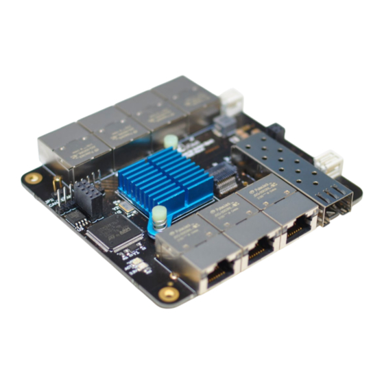
1. INTRODUCTION 1.1. GENERAL NOTES This document outlines and defines the installation, operation, and maintenance procedures for the Ixys 8- Port Ethernet Switch PCB. The manual will contain all relevant data and methods to be able to use and maintain the device for its intended purpose. -
Page 4: Health, Safety And Environment
Page | 4 Doc. No.: 117995-ICS-PD-UMN-0001 Name: User Manual Revision No: 2. HEALTH, SAFETY AND ENVIRONMENT 2.1. GENERAL Safety Notes and General Precautions shall be presented to all personnel concerned prior to testing, operation, maintenance, and repair. The operations shall be performed by the responsible engineer/supervisor. -
Page 5: Specifications
(up to 2.5Gbps). Through stack connectors, the switch can share power and data bus with other Ixys CS range boards. The attached Ixys CS expansion IO boards will automatically be discovered by the switch and the Modbus register list will add registers for the IOs on the connected boards. -
Page 6: Warranty Conditions And Guarantee
Incorrect handling or use of equipment. Packing not carried out in an ESD protective way. 3.4. ORDERING Ixys Part Number Description 117996 PCB CS Ethernet Switch 8port 117997 PCB CS Ethernet Switch 8port w/ 1sfp slots 117998 PCB CS Ethernet Switch 8port w/ 2sfp slots 3.5. -
Page 7: Drawing
Page | 7 Doc. No.: 117995-ICS-PD-UMN-0001 Name: User Manual Revision No: 4. DRAWING... -
Page 8: Operation
Modbus UDP or Modbus TCP protocol according to register list in chapter 7. It is also possible to write parameters by the same protocols. 5.2. SETUP If the switch is stacked to other Ixys CS range boards, then make sure the “CAN-Bus Termination” jumper is attached on at least one of the boards. 5.3. TROUBLESHOOTING / FAULTFINDING Preliminary fault isolation Check The electrical connections are correct as described in drawing in chapter 4. -
Page 9: Communication Protocol
Heartbeat messages are sent once each second to Multicast IP 255.255.255.255 port 65000. These messages can be detected to see IP address if unknown. 6.3. DATA TYPES The following table describes the data types used on Ixys boards. For 32bit values two Modbus registers is used where the first is the most significant. Name... -
Page 10: Registers
Page | 10 Doc. No.: 117995-ICS-PD-UMN-0001 Name: User Manual Revision No: 7. REGISTERS 7.1. READ REGISTERS 7.1.1. HEADER Data Address Description Default Note Type PCB Type Ethernet Switch Type = 45 UINT16 Serial Number UINT16 Firmware Version UINT16 Bit0 = Reserved Status UINT16 Bit1 = Water Alarm... -
Page 11: Write Registers
Page | 11 Doc. No.: 117995-ICS-PD-UMN-0001 Name: User Manual Revision No: 7.2. WRITE REGISTERS 7.2.1. OUTPUTS All Output registers from 500 to 553 and 800 to 1399 are non-volatile and stored on change except for Port Monitoring and disabling that are both reset to zero at reboot. Address Description Default... -
Page 12: Read/Write Registers
Page | 12 Doc. No.: 117995-ICS-PD-UMN-0001 Name: User Manual Revision No: 7.3. READ/WRITE REGISTERS 7.3.1. IO BOARDS Enter the IP address in a web browser and press the “Node Scan” button on the web page to detect attached nodes and add registers for the IO`s on the attached nodes. Press the “Save” button to store the Node list to non-volatile memory. -
Page 13: Detection Of New Node
Node-ID by setting change (Ref.: 6.3.2) of index 0. Be aware that any Ixys boards with jumpers or rotary hex switch set to any Node-ID above 0 will be overridden at power reset to the physically set Node-ID.


Need help?
Do you have a question about the 117996 and is the answer not in the manual?
Questions and answers