
Summary of Contents for Concept Smoke Screen SSI
- Page 1 SMOKE SCREEN INTERFACE Installer Guide (Sentinel Version 1 December 2015) Page 1 of 12...
-
Page 2: Pcb Layout
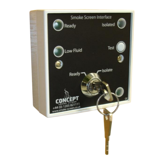
OVERVIEW The Smoke Screen Interface (SSI) is an easily installed control panel that gives the End-User a simple interface with a Smoke Screen to provide status indications, a means of isolating the Smoke Screen from operating or stopping an inadvertent activation and a test facility. - Page 3 “From Panel” Inputs from the Alarm Panel to activate the Smoke Screen and permit the easy use of the SSI test facility. PCB Pin Function SSI Operation Notes Set input from Detects a clean, normally closed circuit going Do not apply a voltage to these pins.
-
Page 4: Operation
INSTALLATION CONNECTIONS Cable entry into the SSI is either via the cut-out in the rear of the enclosure or the installer can drill holes as required in the side of the back-case. Connection schematics for different models of Sentinel PCB are given at the end of this guide; these show example setups to achieve the following functions: ... - Page 5 Smoke Screen Activation Test Function Entering Test Mode. Select the keyswitch to “Isolate” whilst pressing the “Test” button then release the “Test” button. The SSI will now beep permanently to indicate it is in Test Mode. Testing the Smoke Screen. When in Test Mode, as long as any directly attached detectors, ie PIR or door contacts, are operated, pressing the “Test”...
- Page 6 S50 & S70v2, PIR, IAS and full function SSI connection schem atic S50 or S70v2 Pin Function Notes: Trigger "Alarm Set", "Trigger" and "Hold Off" should be This system enables the SSI "Test" facility to activate the Smoke Alarm Set...
- Page 7 S50 & S70v2, PIR, IAS and lim ited function SSI connection schem atic Alarm Panel S50 or S70v2 Pin Function Notes: "Alarm Set", "Trigger" and "Hold Off" should be In this system, to use the SSI "Test" facility to activate the Smoke...
- Page 8 1 Gnd Notes: Trigger "Alarm Set", "Trigger" and "Hold Off" should be This system enables the SSI "Test" facility to activate the Smoke Alarm Set Trigger connected to normally closed clean contacts going Screen, as long as any hold-off is opened, irrespective of the open to fire the Sentinel.
- Page 9 Sentinel pin function Notes: 4 com In this system, to use the SSI "Test" facility to activate the Smoke "Mains Fail Output" changes state if the mains pow er 3 n/c Screen, the Alarm Panel has to be set and have an intruder alarm Mains Fail supply to the Sentinel fails.
-
Page 10: Installer Notes
INSTALLER NOTES Page 10 of 12... - Page 11 INSTALLER NOTES Page 11 of 12...
- Page 12 Concept Smoke Screen Limited 1-2 North End, Swineshead, Lincolnshire, PE20 3LR United Kingdom Tel: +44 (0) 1205 821111 Fax : +44 (0) 1205 820316 Email: info@smoke-screen.co.uk www.smoke-screen.co.uk SSI Installer Guide (Sentinel version 01.12.2015) Page 12 of 12...
Need help?
Do you have a question about the SSI and is the answer not in the manual?
Questions and answers