
Summary of Contents for Hensoldt Kelvin Hughes MK5 SharpEye
- Page 1 Kelvin Hughes MK5 SharpEye Upmast X-band transceiver INSTALLATION, COMMISSIONING, OPERATION & MAINTENANCE KH-2200 issue 4...
-
Page 2: Document History
February 2024 FCC Warnings added. Copyright © 2024 HENSOLDT UK. HENSOLDT, its logo and the product names are registered Trademarks. All rights reserved. When planning any aspect of the installation, commissioning, operation, maintenance or risk analysis (RADHAZ) of the system(s) described in this handbook, it is the responsibility of the individual carrying out the required task to ensure they are working from the latest issue/ revision of this document. -
Page 3: Table Of Contents
Kelvin Hughes MK5 SharpEye Chapter 1: Contents Contents Contents ............3 Installation checklist ........39 Safety notices ..........5 Operator instructions ........41 Introduction ............. 9 Power ON, OFF & system isolation ..41 Control & operation ........41 Overview ............9 Operational states ........ - Page 4 Kelvin Hughes MK5 SharpEye Chapter 1: Contents Page 4 of 76...
-
Page 5: Safety Notices
When working on HENSOLDT UK equipment, operators, Kelvin Hughes RADHAZ RANGE WITHIN WHICH engineers and agents must be trained by HENSOLDT UK to Mk5 SharpEye THE POWER DENSITY EXCEEDS work on their equipment and must work within the health and... - Page 6 All HENSOLDT UK designed equipment is designed to meet that are present when the system is operational which can the requirements of IEC 60950, safety of information include rotating equipment, radiation hazards and where technology equipment.
- Page 7 CD/ DVD or other removable Check that the centre of media, is the copyright of HENSOLDT UK, which will not gravity of the equipment cannot cause the lifting strops or accept any responsibility for any damage or loss caused in ropes to slip or move.
- Page 8 END OF LIFE: When any HENSOLDT UK supplied equipment has reached the end of its serviceable life, the various parts that make up the system should be recycled or disposed of in accordance with all current local industrial waste disposal and recycling regulations.
-
Page 9: Introduction
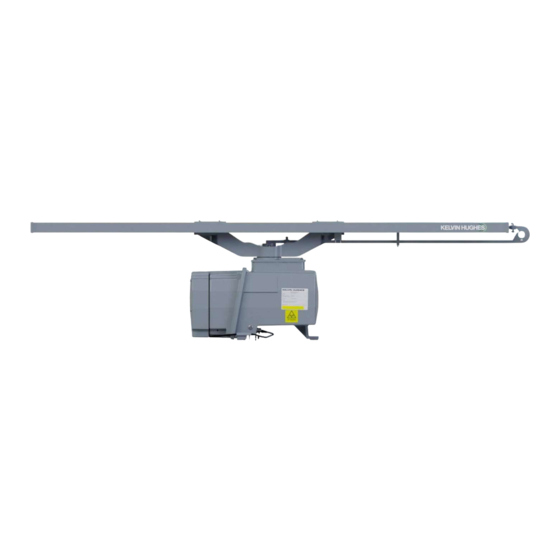
Kelvin Hughes MK5 SharpEye Chapter 3: Introduction Introduction Overview The Kelvin Hughes Mk5 SharpEye consists of an X Band SharpEye transceiver fitted inside a sealed cast aluminium enclosure that can be fitted with either a 1.3m or 1.9m low profile open array antenna (LPA). -
Page 10: Typical System
Kelvin Hughes MK5 SharpEye Chapter 3: Introduction Typical system Page 10 of 76... -
Page 11: Mechanical Installation
Kelvin Hughes MK5 SharpEye Chapter 4: Mechanical installation Mechanical installation Installation considerations & requirements Storage conditions & shelf life PACKING WARRANTY Equipment being stored prior to installation or delivery No provision is allowed to extend the warranty on must be kept in its original packing. When opened or equipment which will be in storage. -
Page 12: Mounting Structure
Kelvin Hughes MK5 SharpEye Chapter 4: Mechanical installation SERVICE ACCESS PLATFORMS & RAILINGS Equipment must be mounted in a position where service access panels can be safely and easily accessed for installation, maintenance and service work. Safe installation/ service access should be provided using platforms where necessary having a minimum size of 1m²... -
Page 13: Recommended Orientation
Where this is not possible, then the equipment is to be protected to prevent dirt and contamination from work being carried out around the equipment. HENSOLDT UK will not be held liable for damage to equipment as a result of poor environmental conditions encountered pre-commissioning. -
Page 14: Recommended Tools
Kelvin Hughes MK5 SharpEye Chapter 4: Mechanical installation CABLES PART NUMBER DESCRIPTION PCV-A137-* DC power connection available in 5, 10 & 15 metre lengths. SCV-A168-* LAN connection available in 5, 10, 15, 20, 25 & 30 metre lengths. Recommended tools... -
Page 15: Unpacking & Lifting
When unpacking, handling or planning the lifting of equipment, refer to the Safety Notices shown in section 2 with specific reference to the sections detailing General Lifting of Equipment, Antenna Lifting and Correct & Incorrect Lifting Procedures. TRANSCEIVER UNPACKING The Kelvin Hughes MK5 SharpEye is shipped in a sealed packing bag within a wooden transit / storage case. -
Page 16: X-Band Lpa Antenna Installation
Kelvin Hughes MK5 SharpEye Chapter 4: Mechanical installation X-band LPA antenna installation The following procedure is identical for both the 1.9m and 1.3m antennas. a) Locate the LPA-A159 Fitting Kit and ensure the contents are correct. The kit is provided with a drawing that gives additional installation information. - Page 17 Kelvin Hughes MK5 SharpEye Chapter 4: Mechanical installation LPA-A159 fitting kit drawing Page 17 of 76...
-
Page 18: Lifting
During the lifting and installation process, ensure that the cable and connector cannot be damaged or crushed. LIFTING/ LIFTING STROPS The Kelvin Hughes MK5 SharpEye may be lifted with the Low Profile Antenna FITTED as illustrated below. Two (2) suitably rated 3m long strops with loops at both ends should be used. -
Page 19: Turning Unit/ Transceiver Installation
Kelvin Hughes MK5 SharpEye Chapter 4: Mechanical installation Turning unit/ transceiver installation MOUNTING FASTENERS The M12 mounting fasteners supplied in the PCV-A154 fitting kit MUST be used to secure the transceiver to the mounting platform and should be tightened to a torque of 50Nm. -
Page 20: Dimensions
Kelvin Hughes MK5 SharpEye Chapter 4: Mechanical installation Dimensions Mounting footprint Page 20 of 76... -
Page 21: 1.3M Antenna
Kelvin Hughes MK5 SharpEye Chapter 4: Mechanical installation 1.3m Antenna Page 21 of 76... -
Page 22: 1.9M Antenna
Kelvin Hughes MK5 SharpEye Chapter 4: Mechanical installation 1.9m antenna Page 22 of 76... -
Page 23: M Antenna
Kelvin Hughes MK5 SharpEye Chapter 4: Mechanical installation 2.5m antenna Page 23 of 76... -
Page 24: Pcv-A2 Ac/Dc Converter
Kelvin Hughes MK5 SharpEye Chapter 4: Mechanical installation PCV-A2 AC/DC converter MOUNTING CONSIDERATIONS The optional PCV-A2 Note is an IPx6 enclosure. The unit should ideally be bulkhead mounted in a position that offers quick, unrestricted access away from direct sunlight in an area offering good ventilation. -
Page 25: Termination
If effort is minimum bend radius of 12 x the cable diameter should be required when connecting or disconnecting, the wrong assumed for HENSOLDT UK supplied cable. technique is being employed. Care should be taken when mating and de-mating... -
Page 26: Connector & Switch Locations
Kelvin Hughes MK5 SharpEye Chapter 5: Termination Connector & Switch locations Earth stud The main casing earth stud must be connected to a proven and tested earth point using the PCV-A156 earth strap supplied in the fitting kit. Alternative grounding cables, braids or arrangements must not be used. -
Page 27: Pcv-A137-* Dc Cable
Kelvin Hughes MK5 SharpEye Chapter 5: Termination PCV-A137-* DC cable Page 27 of 76... -
Page 28: Scv-A168-* Lan Cable
Kelvin Hughes MK5 SharpEye Chapter 5: Termination SCV-A168-* LAN cable Page 28 of 76... -
Page 29: Pcv-A2 Ac/Dc Supply (Optional)
Where a third party AC/ DC Power supply is to be used that is not a HENSOLDT UK supplied item, the unit must be designed in accordance with the requirements of IEC 60950-1:2005. The power supply should be designed in such a way that under single fault conditions, mains/ AC voltages cannot be applied to the DC output. -
Page 30: Cable Clamp
Kelvin Hughes MK5 SharpEye Chapter 5: Termination External fan connection Once the unit has been mechanically installed onto its mounting position, the DC cable for the external fans should be connected. Note CABLE LOCATION The fan cable is supplied taped to the chassis and should NOT be removed until ready for connection.
Need help?
Do you have a question about the Kelvin Hughes MK5 SharpEye and is the answer not in the manual?
Questions and answers