Table of Contents
Advertisement
Quick Links
WeldScanner-S3
Manual and
Technical documentation
Computer-assisted measuring system
for assessment and documentation
of welding processes
HKS-Prozesstechnik GmbH
Heinrich-Damerow-Str. 2
D-06120 Halle / Saale
Tel. +49 (0)345 68309-0
Fax +49 (0)345 68309-49
info@hks-prozesstechnik.de
www.hks-prozesstechnik.de
Advertisement
Table of Contents

Summary of Contents for HKS Prozesstechnik WeldScanner-S3
- Page 1 WeldScanner-S3 Manual and Technical documentation Computer-assisted measuring system for assessment and documentation of welding processes HKS-Prozesstechnik GmbH Heinrich-Damerow-Str. 2 D-06120 Halle / Saale Tel. +49 (0)345 68309-0 Fax +49 (0)345 68309-49 info@hks-prozesstechnik.de www.hks-prozesstechnik.de...
-
Page 3: Table Of Contents
WeldScanner S3 Operating manual and technical documentation 2016-12-06 Table of contents TABLE OF CONTENTS ............................1 DECLARATION OF CONFORMITY ........................2 1. GENERAL NOTES ............................3 1.1 S ............................... 3 AFETY NOTES 1.2 L ..............................3 ICENCE TERMS 1.3 A ............................. -
Page 4: Declaration Of Conformity
WeldScanner S3 Operating manual and technical documentation Declaration of conformity according to DIN EN ISO/IEC 17050 HKS-Prozesstechnik GmbH Heinrich-Damerow-Str. 2 manufacturers name /aderess: D-06120 Halle Deutschland / Germany µQAS-S3 PRODUCTS MODEL S3-Modul WeldScanner S3 WeldAnalyst S3 ... -
Page 5: General Notes
WeldScanner S3 Operating manual and technical documentation 1. General notes Congratulations on purchasing your new WeldScanner. Please read this user manual carefully and in its entirety before using it. 1.1 Safety notes The WeldScanner is a device that is powered by mains voltage. Proper use of the equipment, along with adherence to the safety notes, are the only ways to ensure that you, the user, do not experience any damage or come to any harm. -
Page 6: Area Of Application
WeldScanner S3 Operating manual and technical documentation 1.3 Area of application The WeldScanner S3 can be used as a mobile multimeter, oscilloscope, data logger and power source calibrator. It is a universal aid for welding experts, which can be used for error analysis and welding data documentation as well as for calibrating power sources. -
Page 7: Weldscanner S3 Device Description
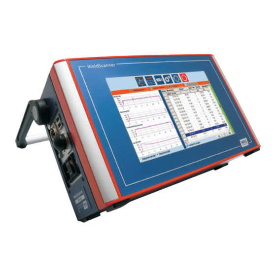
WeldScanner S3 Operating manual and technical documentation 2. WeldScanner S3 Device description 2.1 WeldScannerS3 – Housing 1 Network interface 6 Carrying handle 8 Sensor connection socket 2 USB port 7 Touch display 9 Reserve connection socket 3 Power connection socket 4 Power switch 5 Type plate 2.3 Sensor connection... -
Page 8: Operating The Weldscanner
WeldScanner S3 Operating manual and technical documentation 3. Operating the WeldScanner 3.1 Switching on the device and main menu The WeldScanner features a wide range voltage input with automatic range detection. This ensures that the device can be connected to all common power grids (110 V–230 V). -
Page 9: Begin Recording Weld Seams
WeldScanner S3 Operating manual and technical documentation 3.2 Begin recording weld seams Automatic start The device automatically recognises when a welding process begins, and recording commences. (rec – shows in red) Just as on a multimeter, the current parameters and duration of the welding process are shown. -
Page 10: Displaying And Analysing Recorded Data
WeldScanner S3 Operating manual and technical documentation 3.4 Displaying and analysing recorded data The ‘Analyse’ icon brings up a tabular list of all the measurement values stored in the circular buffer (Fig 1). In this table, the date, time, recording number and mean value of the recorded param- eters, as well as the custom field (writeable field on the start screen) are displayed to the right. -
Page 11: Settings
WeldScanner S3 Operating manual and technical documentation 3.6 Settings Press the ‘Settings’ icon to access the configuration screen. Here you can adjust all the settings relating to the measuring process. Technology Select the welding procedure to be measured in the ‘Technology’... -
Page 12: Pc Software For Analysing The Welding Data
WeldScanner S3 Operating manual and technical documentation 4. PC software for analysing the welding data The supplied WeldScanner PC software enables data recorded with the device to be read and analysed. The software runs on Windows 7 or above. Please see the enclosed instructions for installation information. Program launch Once the PC program is launched, a screen appears that is similar to the... - Page 13 WeldScanner S3 Operating manual and technical documentation Description of the PC software’s menu functions Open This provides you with the option of opening other databases. Import The ‘Import’ button enables you to choose a source directory from which you can load saved data, for example, a USB stick or a different directory.
-
Page 14: Calibration Mode (Optional)
WeldScanner S3 Operating manual and technical documentation 5. Calibration mode (optional) As an additional function of the Definition of terms: WeldScanner, you have the option of unlocking the ‘Calibration mode’. This Calibration Determination of the display deviations mode enables you to calibrate welding between power source and WeldScanner devices, as well as manage and print calibration reports. - Page 15 WeldScanner S3 Operating manual and technical documentation Carrying out calibration (Fig 1) Calibration begins with the first adjustment range => determined by the machine’s parameters. The WeldScanner gives 5 values. It runs through these twice (from bottom to top and vice versa). Each current voltage value to be set also has a certain corresponding resistance value.
-
Page 16: Technical Data Weldsanner-S3
WeldScanner S3 Operating manual and technical documentation 6. Technical data WeldSanner-S3 Größe Einheit operational input voltage 90-132V AC / 180-264V AC, Autorange input fuse T4 A/250 V input frequency 47-63Hz input power min. 3,6W / max. 50W recommended circuit breaker / fuse 6 A (Charakteristik C) or slow blow system perturbation EN 61000-3-2, class A... -
Page 17: Technical Data Of The Welding Processes
WeldScanner S3 Operating manual and technical documentation 7. Technical data of the welding processes You find these on the following sides structured according to the technologies: 1. Arc welding / welding speed 2. Arc welding / seam lenght 3. Arc welding / welding speed / AC 4. - Page 18 Hz basic settings => recording duration in the ring buffer for registration of all channels and recommended sample rate: max. 8 hours => recording duration per seam: max. 60 min HKS-Prozesstechnik GmbH / technical documentation WeldScanner-S3 / technology- table 16.12.2016...
- Page 19 Hz basic settings => recording duration in the ring buffer for registration of all channels and recommended sample rate: max. 8 hours => recording duration per seam: max. 60 min HKS-Prozesstechnik GmbH / technical documentation WeldScanner-S3 / technology- table 16.12.2016...
- Page 20 Hz basic settings => recording duration in the ring buffer for registration of all channels and recommended sample rate: max. 8 hours => recording duration per seam: max. 60 min HKS-Prozesstechnik GmbH / technical documentation WeldScanner-S3 / technology- table 16.12.2016...
- Page 21 Hz basic settings => recording duration in the ring buffer for registration of all channels and recommended sample rate: max. 8 hours => recording duration per seam: max. 60 min HKS-Prozesstechnik GmbH / technical documentation WeldScanner-S3 / technology- table 16.12.2016...
- Page 22 5.000 5.000 5.000 => recording duration in the ring buffer for registration of all channels and recommended sample rate: max. 30 min => recording duration per seam: max. 2 min HKS-Prozesstechnik GmbH / technical documentation WeldScanner-S3 / technology- table 16.12.2016...
- Page 23 20.000 20.000 => recording duration in the ring buffer for registration of all channels and recommended sample rate : max. 30 min => recording duration per seam: max. 2 min HKS-Prozesstechnik GmbH / technical documentation WeldScanner-S3 / technology- table 16.12.2016...
- Page 24 BASIC SETTINGS => recording duration in the ring buffer for registration of all channels and recommended sample rate : max. 30 min => recording duration per seam: max. 2 min HKS-Prozesstechnik GmbH / technical documentation WeldScanner-S3 / technology- table 16.12.2016...
- Page 25 20.000 20.000 => recording duration in the ring buffer for registration of all channels and recommended sample rate : max. 800 sec => recording duration per seam: max. 2 min HKS-Prozesstechnik GmbH / technical documentation WeldScanner-S3 / technology- table 16.12.2016...
- Page 26 BASIC SETTINGS => recording duration in the ring buffer for registration of all channels and recommended sample rate : max. 90 min => recording duration per seam: max. 60 min HKS-Prozesstechnik GmbH / technical documentation WeldScanner-S3 / technology- table 16.12.2016...
Need help?
Do you have a question about the WeldScanner-S3 and is the answer not in the manual?
Questions and answers