
Subscribe to Our Youtube Channel
Summary of Contents for Austdac SILBUS HHP1-S
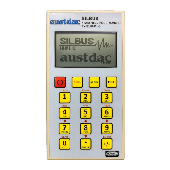
- Page 1 Title SILBUS HAND HELD PROGRAMMER TYPE HHP1-S USER MANUAL Document Number 125-769-12 Issue 1 OF 34...
-
Page 2: Revision Control
Copyright 2024 This document remains the property of Austdac Pty. Ltd. It is subject to its recall and must not be reproduced in part or whole or its contents divulged to third parties without prior written approval from Austdac Pty Ltd. -
Page 3: Table Of Contents
TABLE OF CONTENTS Revision Control ..........................2 TABLE OF CONTENTS ........................3 TABLES ............................4 FIGURES ............................4 TERMINOLOGIES .......................... 4 1 GENERAL DESCRIPTION ......................5 WARNINGS AND PRECAUTIONS (EN) ..................6 AVERTISSEMENTS ET PRÉCAUTIONS (FR) ................6 2 Handheld Overview ........................7 2.1 Case ............................. -
Page 4: Tables
8 CERTIFICATION ........................33 9 SOFTWARE REVISION AND DISPLAY ..................33 10 SPECIFICATIONS ........................34 TABLES Table 1: SILBUS Port Pinout ......................8 Table 2: Configuration Port Pinout ....................8 Table 3: Keypad Functions ......................11 Table 4: List of supported configuration commands ..............27 Table 5: SILBUS Port Connections .................... -
Page 5: General Description
1 GENERAL DESCRIPTION The SILBUS Handheld Programmer and Tester Type HHP1-S is a portable device which is used for: • Real-time monitoring of the SILBUS network • Configuration of SILBUS network components Firmware upgrades of SILBUS system modules • Configuration of SILBUS system modules •... -
Page 6: Warnings And Precautions (En)
There are no user serviceable parts in the HHP1-S. Do not open or modify the HHP1-S. The HHP1-S must only be repaired by an Austdac authorized repairer. Refer to the HHP1-S certification for any special conditions of use. AVERTISSEMENTS ET PRÉCAUTIONS (FR) Le HHP1-S est un produit certifié. -
Page 7: Handheld Overview
2 Handheld Overview 2.1 CASE The HHP1-S comes with a protective leather case. The HHP1-S may be removed from the leather case for battery replacement and access to the micro-SD card slot. The HHP1-S must have a leather case at all times for anti-static protection in hazardous area. 2.2 FRONT PANEL The front panel of the HHP1-S consists of an LCD display and 16 multi-functional buttons. -
Page 8: Silbus Port
2.3.1 SILBUS Port Function SILBUS Signal SILBUS Common Table 1: SILBUS Port Pinout 2.3.2 Configuration Port Function 3V3 Console Port Power RS485 A+ RS485 B- TTL Tx TTL Rx Table 2: Configuration Port Pinout 2.3.3 SILBUS Cable The SILBUS network monitoring cable supplied with the HHP1-S features 2mm banana plugs on the ends, providing the user with an excellent connection to terminals for interfacing with the SILBUS network via Dupline Test Socket (DTS). -
Page 9: Micro-Sd Card
The HHP1-S is supplied with a micro-SD card from Austdac. The capacity and make of the card may vary over time. Use of cards not supplied by Austdac may result in compatibility issues with the HHP1-S. The maximum storage capacity that the HHP1-S can support up to 32GB, and the micro-SD card should be rated as a class 4. -
Page 10: Figure 6: Hand Held Programmer Back Panel (Battery Compartment)
Figure 6: Hand held programmer back panel (Battery compartment) Ensure batteries are orientated correctly. Battery polarity is embossed in the base of the battery compartment for each cell. WARNING: THERE ARE ONLY FOUR TYPES OF BATTERIES THAT ARE CERTIFIED FOR USE WITH THE HHP1-S. -
Page 11: Operating Instruction
3 OPERATING INSTRUCTION 3.1 KEYPAD USAGE The HHP1-S has a multi-functional keypad and the following section describes its functions. Default/ Numeric Navigation Power ON/OFF (Hold for 3 seconds) Delete/Backspace Home Repeat Page Help View Page Down ◄ PQRS (LEFT) ▲ (UP) ►... -
Page 12: Alpha/Numeric Mode
Pressing the MENU key moves back to the previous menu or exit the edit mode and enter the navigate mode. It also toggles between the “Main menu” and the “Austdac” logo. The UP ARROW ▲ / DOWN ARROW ▼ key press moves the menu selection arrow accordingly during navigation mode. -
Page 13: Battery Status
Pressing the REPEAT button on the HHP1-S will continuously repeat the same config functionality in the background and update the output on the screen accordingly for the user. The frequency of the background process is every 10 seconds. The repeat mode will be indicated by the notation ‘R’ in the top right-hand corner of the screen. -
Page 14: Interface Description
The version of the lookup table file, such as "v001" in "lookup_table_v001.txt," may change based on the most recent updates provided by Austdac. The lookup table file is in a .txt format. -
Page 15: Operation
5 OPERATION The operation of the HHP1-S can be categorized into several sections, as outlined on the MAIN MENU page. MAIN MENU > I/O MAP SILBUS CONFIG UP/DOWN ADVANCED SETTINGS Figure 7: LCD – MAIN MENU PAGE 1. I/O MAP 2. -
Page 16: Silbus Tester
SILBUS I/O MAP SILBUS I/O > Normal ABCDEFGHIJKLMNOP Latch █ █ On: ■ Off: □ Figure 8: LCD - I/O MAP In normal mode, it shows what are all the channels enabled/disabled on a real time basis. In latch mode, it will show what channels are enabled/disabled however if a channel is enabled the display will stay enabled allowing the user to capture any glitches in the system. -
Page 17: Group Selection
5.2.1 GROUP SELECTION SILBUS TESTER Tx-LATCH: > N Group: CHANNEL: _________________ A -------- Figure 10: LCD - DIGITAL 1 GROUP By default the arrow will be pointing to the first field “TX-LATCH”. User can press the Up Arrow ▲ / Down Arrow ▼ to enable/disable TX-LATCH. To achieve the Digital Group, functionality user has to disable the TX-LATCH. -
Page 18: Silbus Status [Analink/Fastlink]
5.3 SILBUS STATUS [ANALINK/FASTLINK] The SILBUS STATUS menu displays the analog data over the SILBUS network. This has two modes, • ANALINK FASTLINK • 5.3.1 ANALINK ANALINK STS ADDRESS: >A1 STATUS: FAIL COUNT: 0 VALUE: 0.0% __________________ MENU TO EXIT Figure 12: LCD - ANALINK The ANALINK STATUS screen or menu is used as a tool to show the value and status of a selected Analink analogue channel. -
Page 19: Silbus Setup
User can edit the field “ADDRESS” using the alpha-numeric keypad. User can enter a valid channel. The field “FLINK MARK” will display the Fastlink Sync Marker Channel address set by the user. The 16 bit Fastlink value will be displayed in the field “COUNT”. Valid range is 0x0000 –... -
Page 20: Upload Config
5.5 UPLOAD CONFIG The upload configuration is used to extract the configuration profile of any SILBUS device via the console port and save it as a config file on the micro-SD card. Saved configuration is useful for record keeping and future cloning of a new SILBUS device for maintenance or system expansion. -
Page 21: Download Config
5.6 DOWNLOAD CONFIG The download configuration is used to take a previously saved configuration file from the micro-SD card and download it to the target SILBUS device. This method of configuration ensures exact cloning during maintenance and system expansions. DWNLOAD CFG DWNLOAD CFG DWNLOAD CFG Scanning…... -
Page 22: Advanced
5.7 ADVANCED The ADVANCED option in the menu consists of two features: SW UPDATE (Software Update) and CONFIG (Configuration). Both features are password-protected and can only be accessed by entering the correct password. Upon selecting the ADVANCED option, the LCD screen will prompt the operator to enter a password. This can be accomplished by pressing the ENTER key, followed by the entry of the 4-digit password, 2601, using the keypad. -
Page 23: Config
When there is no SILBUS device found on the console port, the message “No device found” will be displayed to the user. When there is no micro-SD card on the HHP1-S, the message “NO SD Card” will be displayed to the user. Only HEX files that match the connected device name will be listed. -
Page 24: Figure 25: Lcd - Fastlink Marker Setting
In the selected command configuration mode, the user will be required to enter configuration parameters. If the parameter is a number, the keypad will automatically switch to numerical mode. If the required input is alphanumeric, the user should switch the keypad mode by pressing the ALPHA key. -
Page 25: List Of Supported Config Commands
5.9.1 LIST OF SUPPORTED CONFIG COMMANDS Given below are the list of configuration commands supported by HHP1-S for different types of SILBUS devices. BLIP GSW1 Command Command Description Description SBADDR Set Digital Input Address SBCHAN Set number of SILBUS channels BOUNCE Set Digital Input Debounce SBDUAL... - Page 26 SUB1 SMB1 Command Command Description Description SBIRTH SUB1 Birth Reg Access MODE Select Modbus Slave or Master WEBTIME Set/Get Web refresh time MBSET Modbus Address, Baud & Parity Set/Get RTC date & Time MBERR Display Modbus error counters SBMAP Display SILBUS I/O Map FSTMRK Set Fastlink Rx Marker SBSTAT...
-
Page 27: Table 4: List Of Supported Configuration Commands
ABBD2 SNM1 Command Command Description Description Real Time Clock SBVOLT Earth voltage SILBUS channels Display event log dump SBOHMS Earth resistance SILBUS channels MBSET Set Modbus Address, Baud & Parity FSTMRK Set Fastlink marker address MBERR Display MODBUS error counters ANASEL Analog protocol for params INPUT... -
Page 28: Lookup Table
User should not modify or change the contents of the lookup table file. If the lookup table file is missing, users should contact Austdac to obtain the latest file. This ensures that your device operates correctly and efficiently with up-to-date configuration settings. -
Page 29: Additional Features
6 ADDITIONAL FEATURES 6.1 LCD BACKLIGHT The LCD backlight menu has the option to turn ON/OFF the LCD backlight. User when entering this menu must press ENTER key to enter the edit mode and use the Up Arrow ▲ / Down Arrow ▼ to turn ON/OFF the LCD backlight. LCD BACKLIGHT BackLight:>ON Figure 27: LCD - Handheld Settings (LCD Backlight) -
Page 30: About
The System update menu is used to make a firmware upgrade to the HHP1-S devices. The firmware binary “HHP1.a43” will be officially released by Austdac. Only this binary to be loaded into the micro-SD card and it should be loaded before getting into the System update screen. - Page 31 • Boot support If the battery level is less than 25%, the system update will be terminated and the user will be getting a prompt as below, Battery less than safe limit. Replace new battery and retry. If the binary file doesn’t belong to this device, the system update will be terminated and the user will be getting a prompt as below, Binary on the SD card does not...
- Page 32 SYSTEM UPDATE SYSTEM UPDATE IN PROGRESS IN PROGRESS PLEASE WAIT… PLEASE WAIT… ERASING UPDATING TEMP MEMORY TEMP MEMORY SYSTEM UPDATE SYSTEM UPDATE IN PROGRESS IN PROGRESS PLEASE WAIT… PLEASE WAIT… ERASING FINISHING-UP LIVE MEMORY UPDATE Upon a successful firmware update, the device reboots with the new firmware. Check the updated firmware version on the “ABOUT”...
-
Page 33: Connections
7 CONNECTIONS 7.1 SILBUS TEST X4 SILBUS TEST X4 CONNECTIONS CONNECTION DESIGNATION DESCRIPTION RED TEST LEADS WITH CLIP SILBUS NETWORK SIGNAL SILBUS NETWORK BLACK TEST LEADS WITH CLIP COMMON Table 5: SILBUS Port Connections 7.2 SILBUS PRG & CONFIG X6 SILBUS PRG &... -
Page 34: Specifications
10 SPECIFICATIONS General Name SILBUS Hand-Held Programmer and Tester Type HHP1-S Interface SILBUS terminals Configuration Port TTL SILBUS console port Physical Dimensions (Enclosure) 101.6mm (W) x 32.8mm (D) x 190.5mm (H) Dimensions (w/Protective Case) 107mm (W) x 42mm (D) x 200 (H) Mass (w/Case &...
Need help?
Do you have a question about the SILBUS HHP1-S and is the answer not in the manual?
Questions and answers