
Summary of Contents for Huaming CMA7
- Page 1 MOTOR DRIVE UNIT TYPE CMA7 Operating Instruction HM 0.460.302 Shanghai Huaming Power Equipment Co.,Ltd.
-
Page 2: Table Of Contents
6.3 Put into operation at site ⋯⋯⋯⋯⋯⋯⋯⋯⋯⋯⋯⋯⋯⋯⋯⋯⋯⋯⋯⋯⋯⋯⋯⋯⋯⋯⋯ 7. Maintenance ⋯⋯⋯⋯⋯⋯⋯⋯⋯⋯⋯⋯⋯⋯⋯⋯⋯⋯⋯⋯⋯⋯⋯⋯⋯⋯⋯⋯⋯⋯⋯ 20 Appendix 1 Overall dimension diagram ⋯⋯⋯⋯⋯⋯⋯⋯⋯⋯⋯⋯⋯⋯⋯⋯⋯⋯⋯⋯⋯⋯⋯ Appendix 2 Description of all functions of CMA7 Motor Drive Unit ⋯⋯⋯⋯⋯⋯⋯⋯⋯⋯⋯⋯ Appendix 3 Designation of terminals ⋯⋯⋯⋯⋯⋯⋯⋯⋯⋯⋯⋯⋯⋯⋯⋯⋯⋯⋯⋯⋯⋯⋯⋯ Appendix 4 CX output decimal position signal ⋯⋯⋯⋯⋯⋯⋯⋯⋯⋯⋯⋯⋯⋯⋯⋯⋯⋯⋯⋯... -
Page 3: General
1.1 Scope of application CMA7 can be used to drive all type of on-load tap changers as well as off-circuit tap changers. 1.2 Service condition The storage ambient temperature of OLTC is from -25 ℃ to 40 ℃ . The storage humidity of the OLTC should be no more than 85 percent. -
Page 4: Technical Data
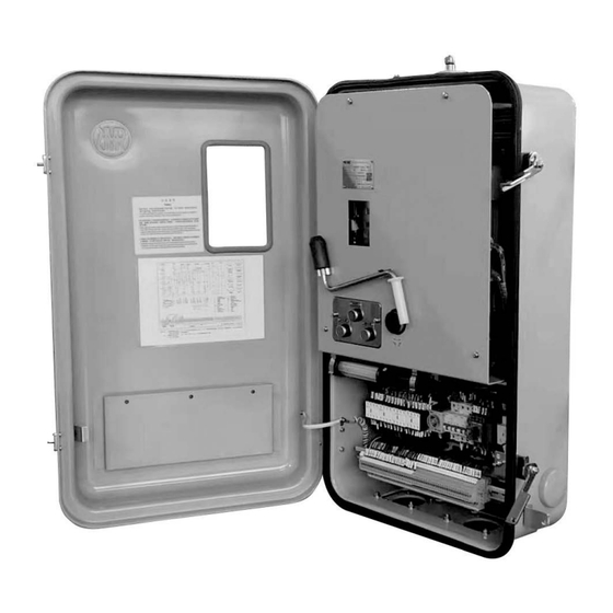
Weight (kg) * special design 3. Structure CMA7 motor drive unit consists of housing, drive mechanism, position indication and electrical control components, etc, please refer to fig.1. 3.1 Housing Housing consists of tank and cover, both of which are made of corrosion-proof aluminum alloy made in... -
Page 5: Gearing System
3.2 Gearing system Showed in fig.2, gear system comprises motor, pulley box, poly-V- driving belt, two end positions limits, transmission gear for manual operation. The poly-V-driving belt is installed inside cast aluminum alloy box, etc. Belt shaft and transmission gear shaft are structured as sleeve shaft and connected by mechanical clutch which is used for mechanical limit protection of motor drive unit, when the mechanical limit is actuated, then clutch acts, the motor will stop running. -
Page 6: Electrical Components
HM0.460.302 3.4 Electrical components H1: Signal lamp, with lamp holder, for tripping off motor protective switch Q1 K1/K2: Contactor for controlling direction of motor 1 → N: K1 close N → 1: K2 close K3: Brake contactor K20: Auxiliary contactor for step-by-step control M1: Motor Q1: Motor protective switch with magnetic tripping R1: Heater... -
Page 7: Operating Principle
4. Operating principle 4.1 Mechanical operation principle (fig.4) Normally the motor drive unit is operated electrically, but it might be operated manually during inspection or maintenance. Motor drives big drive wheel 3 via small drive wheel 2, then force will be transmitted to drive shaft 4 through which the tap changer is operated. - Page 8 “Up” when in clockwise 103. lever 123. coupling section 104. Tap change indication wheel 124. resistance ring 105. internal gear plate 125. coupling section pin 106. planet gear 126. guiding unit Fig.4 Mechanical principle diagram of Type CMA7 motor drive unit...
-
Page 9: Control Circuit
4.2.2 Control circuit Control circuit is connected to L1 and N via X1/6,7, Q1(13,14), S18(NC,C), S8(S,V), and control voltage will be interrupted once one of Q1,S18,S8 acts. Trip circuit of Q1 is interlocked with control circuit. Motor protective switch Q1 equips with a trip coil which could be energized through push-button S5, safety circuit or protective circuit against run-through positions. -
Page 10: Indication Circuit Of Remote Position
HM0.460.302 4.2.5 Indication circuit of remote position Digital remote position signal transmitter adopts code-dial sliding contacts which acts in way of break- before-make from one position to next one, together with position indicator to display position. The fixed contacts on position transmitter are connected to terminals on socket according to decimal system. 4.2.6 Heating circuit Heating resistor is permanently connected to power supply L1 and N via terminal X1/4, 5. - Page 11 220V/50Hz 380V/3PH/50Hz X1-6 X1 1 2 1 3 5 X1-11 X1-24 X1-23 X1-8 X1-9 I> I> I> /1.G6 X1-14 /1.F6 22 32 42 52 21 31 41 51 3 5 1 V1 U1 X1-7 X1-13 4.3.1.1 Start-up circuit 220V/50Hz X1-6 X1-24 X1-11 X1-23...
- Page 12 HM0.460.302 N/O contact of K1 (13, 14) close when K1 is energized, which make K3 energized, then the motor starts up, at the same time K21 (A1, A2) is energized to initiate time delay. 4.3.1.2 Step-by-step control As the motor begins to run, the green field on the indication wheel 104 will turn out of inspection window, N/C contact of cam switch S14(C,NO1) close, by which simultaneously energizes the contactor K1(A1,A2).
-
Page 13: Passage Of Positions For Middle Positions
The operation goes towards “1” position. Press push-button S2 Contactor K2 is energized Braking contactor K3 is energized Motor runs reversely Cam switch S12 is actuated Subsequent steps will be same as that of operation going towards “N” position. The sequence of tap change operation from one position to adjacent one (equal to 33 sections on step-by- step indication wheel 104), operation status of each control element as follows Closing sequence: S1 (S2), K1 (K2), K3 S14 (S12), S13, K20... - Page 14 HM0.460.302 4.3.3.1 Protection for end position 220V/50Hz 380V/3PH/50Hz N/C contact (C-NC) of limit switch S16 ( at position N ) or of S17 (at position 1) will open when driving X1 1 X1-6 mechanism runs to end position, therefore, contactor K1 or K2 can not be energized any more.
- Page 15 2(C,NO2),K2(41,42),S13(NC1,NC2) and trip off switch Q1, as a result, main circuit and control circuit are disconnected, and the motor stops running, in this case, interchange any two of lines L1,L2,L3,then operate the motor drive unit by hand crank to turn the indication wheel 104 untilthe red mark gets to the center of inspection window again, switch on Q1 and then operate motor drive mechanism again.
-
Page 16: External Connection Circuit
HM0.460.302 4.3.3.6 Protection against run-through positions Delay time of time relay K21 is set at a certain value, if the driving mechanism runs through the positions continuously when losing control signal, time to energize K21 will exceed set value, causing K21 (6-8) closed, Q1 will trip power off. - Page 17 220V/50Hz X1-6 /1.F8 X1-24 X1-23 X1-11 X1-12 X1-9 X1-8 /1.G6 /1.G7 /1.G7 X1-25 X1-26 /1.F7 /1.F5 /1.G8 /1.G8 X1-14 /1.F4 /1.G6 /1.G6 /1.G8 /1.G8 /1.F4 /1.F6 /1.G8 /1.F6 X1-27 X1-28 /1.G6 /1.G6 /1.F4 /1.F6 /1.G8 /1.F4 /1.F6 /1.F5 /1.G7 /1.F6 /1.F4 /1.F5 /1.F8...
-
Page 18: Installation
HM0.460.302 5. Installation 5.1 Mount motor drive unit onto transformer tank (refer to appendix 1) The motor drive unit should be mounted on a flat and straight surface or plate of external transformer tank by four studs, otherwise, it will be easily deformed and will cause difficulty in closing the cover, even affect normal operation. -
Page 19: Commissioning
For both direction N → 1 and 1 → N, number differences of section that the indication wheel turns from the completion of tap change operation to where red mark get to the center of inspection window should be basically identical, a slight dissymmetry is permissible. Connection should be done as follows a. - Page 20 HM0.460.302 a, b: Count the number of section to the end for both direction separately, 7 sections for 1 → N, 1.5 sections for N → 1; c: Turn hand crank towards direction with more sections to end; d: Unfasten the coupling; e: Turn hand crank as per calculated sections;...
-
Page 21: Transportation Of Transformer
6.1.2 Test for mechanical end stop device Tap changer can move to last position within its tap change range, but can’t approach its limit position, while motor drive unit can turn to its limit position by manual operation, about 2-3 revolutions before mechanical end stop is actuated. -
Page 22: Appendix 1 Overall Dimension Diagram
HM0.460.302 Appendix 1 Overall dimension diagram Unit: mm... -
Page 23: Appendix 2 Description Of All Functions Of Cma 7 Motor Drive Unit
Appendix 2 Description of all functions of CMA 7 Motor Drive Unit Description Remark Manual operation Electrical operation Remote operation Protection of limit position Protection of phase sequence Protection of manual operation Automatic re-start after temporary control voltage break-down Emergency stop Position indication Raise 1 →... -
Page 24: Appendix 3 Designation Of Terminals
HM0.460.302 Appendix 3 Designation of terminals X1 terminal number Description 1,2,3,5 Power-in end, line voltage L1,L2,L3: 380V/50Hz; Phase voltage L1 to N: 220V/50Hz Input terminal for remote control “1 → N” 10,11 Input terminal for remote control “N → 1” Common terminal for remote control Input terminal for remote control “stop”... - Page 26 HM0.460.302 Note! 1. Please ensure that this opreation instruction has been understood before operating this motor drive unit 2. The concerned documents may be revised due to the modification of products...
- Page 27 Shanghai Huaming Power Equipment Co., Ltd. Address: No 977 Tong Pu Road, Shanghai 200333, P.R.China Tel: +86 21 5270 3965 (direct) +86 21 5270 8966 Ext. 8688 / 8123 / 8698 / 8158 / 8110 / 8658 Fax: +86 21 5270 2715 Web: www.huaming.com...
Need help?
Do you have a question about the CMA7 and is the answer not in the manual?
Questions and answers