Table of Contents
Advertisement
Quick Links
Advertisement
Table of Contents

Summary of Contents for Schiller BP-200 plus
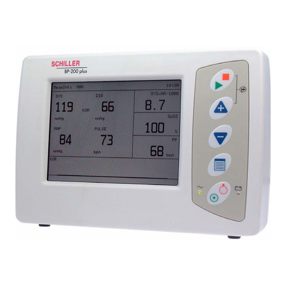
- Page 1 BP-200 plus Stress Test Blood Pressure Monitor User Guide...
-
Page 2: Sales And Service Information
Sales and Service Information The SCHILLER sales and service centre network is world-wide. For the address of your local distributor, contact your nearest SCHILLER subsidiary. In case of difficulty a complete list of all distributors and subsidiaries is provided on our internet site: www.schiller.ch... -
Page 3: Table Of Contents
Terms of Warranty ................12 Introduction ..........13 Overview................13 Operating and Display Elements ........14 2.2.1 BP-200 plus Control Keys and Indicators ........14 Modes of Operation............15 Back Panel ................16 Side Panel ................17 LCD Screen ................. 18 BP-200 plus Menu Structure.......... - Page 4 4.2.8 Interrupting an Ongoing Measurement ..........35 4.2.9 Continuous Short Term Measurement..........36 4.2.10 Ending Continuous Short Measurement .......... 36 Using the BP-200 plus with a Host System...... 37 4.3.1 Procedure ..................37 4.3.2 Interrupting an Individual Measurement........... 38 4.3.3 Viewing the Measurements on the BP-200 plus ......
- Page 5 BP-200 plus Definitions ..........52 Mean Arterial Pressure ............52 Double Product ..............52 Technical Data ........53 BP-200 plus ................. 53 SpO2 Module and ECG Amplifier Option ......55 8.2.1 SpO 2 - Pulsoximetry ................ 55 8.2.2 ECG Amplifier .................. 55 Accessories ..........
- Page 6 BP-200 plus Page 6...
-
Page 7: Safety Notes
Intended Use The BP-200 plus is intended to be used as an adjunct to exercise stress testing devices. It is intended to measure and display diastolic and systolic blood pressure, heart rate, percentage of oxygen saturation in arterial blood (SpO2) and pulse rate in adult or adolescent patients during stress tests. -
Page 8: Safety-Conscious Operation
Operating the device with defective cables may constitute a danger to life. Therefore: – Do not operate the BP-200 plus if the earth connection to the transformer is sus- pect or the mains lead is damaged or suspected of being damaged. -
Page 9: Maintenance
Safety Notes BP-200 plus User Guide Maintenance Maintenance Before cleaning, switch off the device and disconnect the power supply transformer Do not use high temperature sterilisation processes (such as autoclaving). Do not use E-beam or gamma radiation sterilisation. Do not use solvent or abrasive cleaners on either the unit or cable assemblies. -
Page 10: Safety Symbols And Pictograms
Safety Notes Safety Symbols and Pictograms BP-200 plus Safety Symbols and Pictograms 1.8.1 Symbols used in this Document The following overview shows the safety symbols and pictograms used in this manual. For a direct danger which could lead to severe personal injury or to death. -
Page 11: Symbols Used On The Device
Equipment/components and accessories no longer required must be disposed of in a municipally approved collection point or recycling centre. Alternatively, you can return the equipment to your supplier or SCHILLER AG for disposal. Improper disposal can harm the environment and human health. -
Page 12: Additional Terms
• assembly operations, extensions, readjustments, modifications, or repairs are car- ried out by persons authorised by him, and • the BP-200 plus and approved attached equipment is used in accordance with the manufacturer's instructions. There are no express or implied warranties which extend beyond the warranties hereinabove set forth. -
Page 13: Introduction
– Continuous mode that takes BP measurements continuously over a 15 minute period. When used with a stress test system, the BP-200 plus uses a QRS trigger signal to reduce signal artefacts. The unit is powered by an external low voltage medical grade dc power supply and also has slots for four optional AA size batteries for backup. -
Page 14: Operating And Display Elements
Operating and Display Elements BP-200 plus Operating and Display Elements 2.2.1 BP-200 plus Control Keys and Indicators On / Off Key Use this key to switch the unit on or off (b). Power Indicators The power LED indicator (a) is lit when external power is connected. -
Page 15: Modes Of Operation
Introduction BP-200 plus User Guide Modes of Operation Down Arrow Key This key has three functions dependent on monitor display: When in a menu, this key selects the next menu option. When in an options sub-menu, this key selects the next setting. -
Page 16: Back Panel
Back Panel ♥ ♥ All externally connected hardware must be approved by SCHILLER. Connection of any hardware not approved by SCHILLER is at the owner‘s risk. The unit guarantee may also be invalid. (also see page Patient Connectors / Sensors... -
Page 17: Side Panel
Introduction BP-200 plus User Guide Side Panel Side Panel (1) Mini SD card slot - this is used for program updates and storage of raw data for analysis. (2) USB connector. (3) Speaker. Page 17... -
Page 18: Lcd Screen
– In Host Mode - a display to show that the unit is in host mode and a count-up timer indicating the total time elapsed from the start of the test, i.e. from the first measurement taken with the BP-200 plus, e.g. HOST .. 5:07 – In Short term continuous mode - an indication that continuous measurement mode is active and a count-down timer showing the time that the continuous measurement has been active, e.g. -
Page 19: Bp-200 Plus Menu Structure
Introduction BP-200 plus User Guide BP-200 plus Menu Structure (5) Double product value. (6) This field changes according to the version: – For the ECG and SpO2 version this field displays the SpO2 value and peripheral pulse measurement. – For the standard version a single field is displayed showing the current cuff pressure. -
Page 20: Bp-200 Plus Menu Table
Introduction BP-200 plus Menu Structure BP-200 plus 2.7.3 BP-200 plus Menu Table Main Menu Options Value/Options/Notes SETUP SYSTEM Contrast (monochrome • 1 (brightest) to 10 (darkest). Note that this menu item is present LCDs only) only when black and white LCDs are installed. When a colour LCD screen is installed, this contrast menu is not required. - Page 21 Introduction BP-200 plus User Guide BP-200 plus Menu Structure Main Menu Options Value/Options/Notes SETUP MEASUREMENTS Beep Mode • None - no audible beep • Pulse - audible beep for every pulse detected (Continued) • Finish - single audible beep at the end of a measurement •...
-
Page 22: Initial Preparation
• Do not allow the unit to come into contact with acidic vapours or liquids. • The BP-200 plus should not be placed in the vicinity of X-ray or diathermy units, large transformers or electric motors. It must also be positioned at least one metre from the mains supply. -
Page 23: Potential Equalisation
The potential equalisation stud at the rear of the unit is used to equalise the ground potential of the BP-200 plus to that of all mains powered equipment in the vicinity. It is recommended that the BP-200 plus is connected to the hospital or building common ground at all times. -
Page 24: Connection To A Host System
Following are two typical examples of the connections and settings required to connect and setup the BP-200 plus for host system operation. The two examples are for the CS-200 and for the AT-10 plus. Other host systems will be similar - please consult the relevant user guide. -
Page 25: Cs-200 Connections
Defining the trigger pulse In the system configuration menu select: System > Settings > System Configuration > Other System The signal is a TTL logic level of 5 V. For use with the BP-200 plus make the following settings: • QRS trigger: •... -
Page 26: At-10 Plus Connections
Defining the trigger pulse In the system menu select: Menu Key > Peripherals > QRS Trigger The signal is a TTL logic level of 5 V. For use with the BP-200 plus make the following settings: • QRS Trigger: On Duration (ms) •... -
Page 27: Blood Pressure Measurement
The cuff must not be attached to a limb that is already used for interventions such as infusions. To ensure correct arterial pressure, apply the cuff on the same level as the right atrium. A list of BP-200 plus error messages is given in the Maintenance section (see page 48). Page 27... -
Page 28: Applying The Cuff
Blood Pressure Measurement Applying the Cuff BP-200 plus Applying the Cuff Select the appropriate cuff size according to the patient's upper arm. Three cuff sizes are available as follows: To fit arm size Cuff Designation Midpoint Arm Circumference (cm) 18 - 26... - Page 29 Blood Pressure Measurement BP-200 plus User Guide Applying the Cuff A cuff that is applied to a patient in the recumbent or sitting position is normally located at the same level as the heart. However, if the cuff is located at a level higher than the heart (for instance if the arm of a patient in bed is lifted), this may result in lower-than- actual measurement readings (approx.
-
Page 30: Fixing The Microphone Directly On The Upper Arm
If the patient‘s pulse is weak the microphone may be removed from the cuff and placed directly on the upper arm to obtain more secure measurements. A shaped adhesive pad is a standard accessory (SCHILLER Art. No. 2.100326 ) for this purpose. To place the microphone directly on the arm proceed as follows: 1. -
Page 31: Using The Bp-200 Plus In Standalone Mode
Danger of destroying the device during defibrillation. The device is CF protected only when the original SCHILLER patient cable is used. The BP-200 plus uses a 4-lead cable for 2-channel recording. The BP-200 plus uses both channels to determine the QRS pulse. The recommend electrode positions to obtain an good trigger are as follows: •... -
Page 32: Setup
Blood Pressure Measurement Using the BP-200 plus in Standalone Mode BP-200 plus 4.2.3 Setup MAIN MENU SETUP SYSTEM SETUP MEASUREMENTS SETUP VIEW SETUP LIMITS DISPLAY MEASUREMENTS STOP MEASUREMENTS INFO SYSTEM BACK Press the menu key and Select Setup Measurement (a). -
Page 33: Taking Measurements At Predefined Intervals
Blood Pressure Measurement BP-200 plus User Guide Using the BP-200 plus in Standalone Mode 4.2.4 Taking Measurements at predefined intervals Position cuff on the patient (see page 27). If carrying out a stress test position the ECG electrodes (with ECG / SpO2 version only). -
Page 34: Ending The Measurement Program
Blood Pressure Measurement Using the BP-200 plus in Standalone Mode BP-200 plus 4.2.5 Ending the Measurement Program MAIN MENU SETUP SYSTEM SETUP MEASUREMENTS SETUP VIEW SETUP LIMITS DISPLAY MEASUREMENTS STOP MEASUREMENTS INFO SYSTEM BACK Press the Menu key and select Stop Measurements (b) from the main menu 4.2.6... -
Page 35: Taking An Individual Measurement
Blood Pressure Measurement BP-200 plus User Guide Using the BP-200 plus in Standalone Mode 4.2.7 Taking an Individual Measurement In the Measurement Interval menu option (in Setup menu - see page 32) define Manual. Press the Measurement key to take a measurement. -
Page 36: Continuous Short Term Measurement
Blood Pressure Measurement Using the BP-200 plus in Standalone Mode BP-200 plus 4.2.9 Continuous Short Term Measurement Repeated short term measurements can affect venous return and cause venous congestion. Press and hold the + key and press the Measurement key to take continuous measurements (2 second interval between measurements), over a period of 15 minutes. -
Page 37: Using The Bp-200 Plus With A Host System
Blood Pressure Measurement BP-200 plus User Guide Using the BP-200 plus with a Host System Using the BP-200 plus with a Host System 4.3.1 Procedure MAIN MENU SETUP SYSTEM SETUP MEASUREMENTS SETUP VIEW SETUP LIMITS DISPLAY MEASUREMENTS STOP MEASUREMENTS INFO SYSTEM BACK 1. -
Page 38: Interrupting An Individual Measurement
Blood Pressure Measurement Using the BP-200 plus with a Host System BP-200 plus 4.3.2 Interrupting an Individual Measurement Press the Measurement key to interrupt a measurement. 4.3.3 Viewing the Measurements on the BP-200 plus The measurements will normally be viewed on the host system. The trend results can also be viewed during the recording (see following), or can be viewed on the BP-200 plus as a Measurement result. -
Page 39: During The Recording
BP readings and signal quality during a measurement. 4.4.5 Continuous Short Term Measurement Continuous short term measurements and single measurements can be commenced at any time (see page 36). These measurements are not sent to the host and are viewed on the BP-200 plus only. Page 39... -
Page 40: Spo2 And Peripheral Pulse
Safety Notes Pulse oximeter probes and probe cable extenders are designed for use with specific monitors. Only use Massimo sensors recommended from SCHILLER for measurement with the BP-200 plus. Other SpO sensors may lead to improper performance or inaccurate results. -
Page 41: Placing The Sensor
SpO2 and Peripheral Pulse BP-200 plus User Guide Placing the Sensor Alarms No Spo2 alarms will be displayed if communication fails between Sensor and Massimo Sp02 module or a general module failure. The values for PP and Spo2 shows in this case two dashes. -
Page 42: Maintenance
All software controlled devices have undergone a software risk analysis to minimise any hazards connected to software defects. Maintenance work not described in this chapter may only be accomplished by a qualified technician authorised by SCHILLER. The following table indicates the intervals and responsibilities of the maintenance work required. -
Page 43: Visual Inspection
Maintenance BP-200 plus User Guide Visual Inspection Visual Inspection Visually inspect the unit, cables, connectors, tubing, cuff and all sensors for the following: Device casing not broken, cracked or damaged in any way. LCD screen not scratched, cracked or damaged in any way. -
Page 44: Key Test
The batteries must be disposed of in municipally approved areas. Calibration The unit must be returned to a SCHILLER approved centre for calibration every year. A reminder message is displayed 30 days before calibration is due; the unit counts down the subsequent days every time the unit is switched on. -
Page 45: Cleaning
6.6.2 Cleaning the Unit The casing of the BP-200 plus, cable assembly and pressure tube can be cleaned with a soft damp cloth on the surface only. Where necessary a domestic non-caustic cleaner can be used for grease and finger marks. -
Page 46: Removing The Microphone And Inflation Bladder
Maintenance Cleaning BP-200 plus 6.6.4 Removing the Microphone and Inflation Bladder • Slide your hand into the cuff and pull out the inflation bladder. • Gently remove the microphone by pushing out from the microphone pouch. Do not pull on the microphone lead or hose as this can cause damage to the connections. -
Page 47: Re-Inserting The Microphone And Inflation Bladder
Maintenance BP-200 plus User Guide Cleaning 6.6.5 Re-inserting the Microphone and Inflation Bladder The hose/microphone assembly between the cuff and the unit can be positioned so that it exits from the top or the bottom of the cuff according to user preference. -
Page 48: Bp-200 Plus Error Messages
Maintenance BP-200 plus Error Messages BP-200 plus BP-200 plus Error Messages The following is a list of the error message that can appear on the BP-200 plus. 6.7.1 Error Message Table Message Cause Remedy Replace with fully charged accumulators. • Backup batteries voltage too Battery low low to take a measurement. - Page 49 Maintenance BP-200 plus User Guide BP-200 plus Error Messages Message Cause Remedy Avoid moving the arm during measurement. • Minimum pressure reached SYS not detected without systolic value detected (OSC). Repeat measurement; check cuff. No pulse • No pulse detected (OSC).
-
Page 50: Trouble Shooting
Maintenance Trouble Shooting BP-200 plus Trouble Shooting Trouble shooting procedures are subject to verification. Error Cause Remedy Check the cuff position. NIBP • No cuff connected or not correctly fitted. • Incorrect Cuff size Change cuff. • Inaccurate Measurement Check cuff position. -
Page 51: Electromagnetic Radiation
Recommended safety distances between portable and mobile HF telecommunication devices and the BP-200 plus The BP-200 plus is designed for operation in an electromagnetic environment with controlled HF disturbance. The user can help avoid electromagnetic disturbances by keeping the minimum distance between portable and mobile HF telecommunication... -
Page 52: Definitions
Definitions Mean Arterial Pressure BP-200 plus 7 Definitions Mean Arterial Pressure For oscillometric measurements, the MAP measurement given is the value measured by the unit. For Auscultatory measurements, the MAP is calculated as follows: MAP = DIA + (SYS - DIA) -
Page 53: Technical Data
Deflation rate Measurement Intervals On demand from host. Manual measurement interruption Manual, or automatic (2 ...20 minute intervals) Host system Standalone QRS Trigger Primary from external ECG source (host system) Secondary from optional BP-200 plus 4 lead patient cable Page 53... - Page 54 Technical Data BP-200 plus BP-200 plus Standards Non-invasive sphygmomanometers - Part 1 General requirement EN 1060-1, 1995 Non-invasive sphygmomanometers - Part 3 Supplementary requirements for electromechan- EN 1060-3, 1997 ical blood pressure measuring systems Non-invasive sphygmomanometers. Part 4 Test procedures to determine the overall system...
-
Page 55: Spo2 Module And Ecg Amplifier Option
Technical Data BP-200 plus User Guide SpO2 Module and ECG Amplifier Option SpO2 Module and ECG Amplifier Option 8.2.1 - Pulsoximetry Module Masimo™ Amplifier Fully isolated, defibrillation protected >5kV Sampling Frequency 62.5 Hz Operation Normal and high Accuracy • Adults 70 to 100% ± 2 digits •... -
Page 56: Accessories
Your local representative stocks all the disposables and accessories available for the BP-200 plus. A full list of all SCHILLER representatives can be found on the SCHILLER website (www.schiller.ch). In case of difficulty, contact our head office in Switzerland. Our staff will be pleased to help process your order or to provide any details for all SCHILLER products. -
Page 57: 10 Index
Battery symbol ........Blood Pressure Classification ....BP Recording ........BP-200 plus Error Messages ....Operating and Display Elements ... BP-200 plus with a Host System ... Operation Overview ......Calibration ..........Potential Equalisation ......Cleaning ..........Power Supply ........ - Page 58 Index BP-200 plus Page 58...
Need help?
Do you have a question about the BP-200 plus and is the answer not in the manual?
Questions and answers