Table of Contents
Advertisement
Quick Links
OP E R AT ING MA NUA L
R OOM A IR CON DIT ION E R
FLOOR CON S OLE /
U N DE R CE ILIN G DU A L T Y PE
Indoor U nit
A B Y 14A G
A B Y 14R G
A B Y 18A G
A B Y 18R G
A B Y 24A G
A B Y 24R G
Outdoor U nit
A OY 14A N
A OY 14R N
A OY 18A Z
A OY 18R Z
A OY 24A B
A OY 24R Z
K E E P T HIS OPE R AT ION M A N U A L
FOR FU T U R E R E FE R E N CE
FUJITSU GENERAL LIMITED
P/N 9360369017-03
Advertisement
Table of Contents

Subscribe to Our Youtube Channel
Related Manuals for Fujitsu ABY14AG


Summary of Contents for Fujitsu ABY14AG
- Page 1 A OY 24A B A OY 24R Z K E E P T HIS OPE R AT ION M A N U A L FOR FU T U R E R E FE R E N CE FUJITSU GENERAL LIMITED P/N 9360369017-03...
-
Page 2: Table Of Contents
CONTENTS SAFETY PRECAUTIONS ........2 SWING OPERATION ..........12 FEATURES AND FUNCTIONS ......3 ENERGY SAVE OPERATION ....... 13 NAME OF PARTS ........... 4 MANUAL AUTO OPERATION ......13 PREPARATION ............6 CLEANING AND CARE ........14 OPERATION ............7 TROUBLESHOOTING .......... -
Page 3: Features And Functions
FEATURES AND FUNCTIONS AUTOMATIC OPERATION G COOLING MODEL Merely press the START/STOP button, and the unit will begin automatic operation in the Cooling or Dry mode as appropriate, in accordance with the thermostat setting and the actual temperature of the room. G HEAT &... -
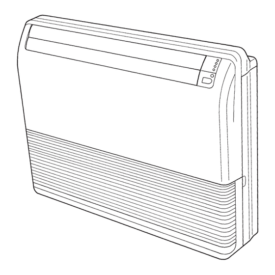
Page 4: Name Of Parts
NAME OF PARTS Instructions relating to heating (*) are applicable only to “HEAT & COOL MODEL” (Reverse Cycle). Fig. 1 Fig. 2 Fig. 4 Fig. 3 Fig. 5 SLEEP TIMER CLOCK AUTO COOL CLOCK TIMER SLEEP MASTER CONTROL TEMP TIME CONTROL ON TIMER RESET ENERGY SAVE... - Page 5 Fig. 1 Indoor Unit Fig. 5 Remote Control Unit 1 Operating Control Panel (Fig. 2) H SLEEP Button 2 MANUAL AUTO button I MASTER CONTROL Button 3 Remote Control Signal Receiver J SET TEMP./SET TIME Buttons ( 4 OPERATION Indicator Lamp (red) K Signal Transmitter 5 TIMER Indicator Lamp (green) L TIMER Button...
-
Page 6: Preparation
PREPARATION CAUTION! Turn on the Power G Take care to prevent infants from accidentally swallowing batteries. Connect the power supply plug to an electrical outlet; in the G When not using the remote control unit case of a direct line connection, turn on the circuit breaker. for an extended period, remove the batteries to avoid possible leakage and damage to the unit. -
Page 7: Operation
OPERATION Instructions relating to heating (*) are applicable only to “HEAT & COOL MODEL” (Reverse Cycle). To Select Mode Operation Press the START/STOP button. SLEEP TIMER The indoor unit’s OPERATION indicator lamp (red) will light. The air conditioner will start operating. Press the MASTER CONTROL button to select the de- COOL sired mode. - Page 8 OPERATION Instructions relating to heating (*) are applicable only to “HEAT & COOL MODEL” (Reverse Cycle). About Mode Operation AUTO: COOLING MODEL G When the room temperature is 2 °C higher than the set temperature, the mode will Cooling Operation switch between Cooling and Drying.
-
Page 9: Timer Operation
TIMER OPERATION Instructions relating to heating (*) are applicable only to “HEAT & COOL MODEL” (Reverse Cycle). Before using the timer function, be sure that the remote control unit is set to the correct current time (See page 6). To Use the ON timer or OFF timer SLEEP TIMER Press the START/STOP button... -
Page 10: Sleep Timer Operation
TIMER OPERATION About the PROGRAM timer About the ON timer G The PROGRAM timer allows you to integrate OFF timer G The timer function is designed to bring your room to a and ON timer operations in a single sequence. The se- comfortable temperature by the set time;... -
Page 11: Adjusting The Direction Of Air Circulation
ADJUSTING THE DIRECTION OF AIR CIRCULATION Instructions relating to heating (*) are applicable only to “HEAT & COOL MODEL” (Reverse Cycle). Vertical (up-down) direction of airflow is adjusted by pressing the remote control unit’s AIR FLOW DIRECTION VERTICAL SET button. Horizontal (right-left) direction of airflow is adjusted by pressing the remote control unit’s AIR FLOW DIRECTION HORIZONTAL SET button. -
Page 12: Swing Operation
SWING OPERATION Begin air conditioner operation before performing this procedure. To select Vertical airflow SWING Operation Press the AIR FLOW DIRECTION VERTICAL SWING button. SWING SWING The SWING indicator lamp (VERTICAL SWING) (orange) will light. In this mode, the UP/DOWN air direction flaps will swing automatically to direct the TIME TEST ENERGY... -
Page 13: Energy Save Operation
ENERGY SAVE OPERATION Instructions relating to heating (*) are applicable only to “HEAT & COOL MODEL” (Reverse Cycle). The air conditioner can be operated while keeping energy consumption costs down. How To Use the ENERGY SAVE OPERATION SWING SWING Press the START/STOP button (if the unit is already operating, proceed to step 2). -
Page 14: Cleaning And Care
CLEANING AND CARE G Before cleaning the air conditioner, be sure to turn it off and disconnect the power supply cord. CAUTION! G Be sure the intake grille is installed securely. G When removing and replacing the air filters, be sure not to touch the heat exchanger, as per- sonal injury may result. -
Page 15: Troubleshooting
TROUBLESHOOTING Instructions relating to heating (*) are applicable only to “HEAT & COOL MODEL” (Reverse Cycle). In the event of a malfunction (burning smell, etc.), immediately stop operation, disconnect the WARNING! power supply plug, and consult authorized service personnel. Merely turning off the unit’s power switch will not completely disconnect the unit from the power source. -
Page 16: Operating Tips
TROUBLESHOOTING Instructions relating to heating (*) are applicable only to “HEAT & COOL MODEL” (Reverse Cycle). Symptom Items to check See Page G Is the power supply plug disconnected from its outlet? CHECK ONCE Doesn’t operate at all: MORE G Has there been a power failure? —... - Page 17 In this event, the TIMER indicator lamp (green) will flash (see page. 5). Temperature and Humidity Range Cooling/Dry Mode *Heating Mode About 21 to 43 °C Outdoor temperature ABY14AG — COOLING MODEL ABY18AG About 21 to 52 °C — ABY24AG About 21 to 43 °C...
-
Page 18: Specifications
SPECIFICATIONS MODEL INDOOR UNIT ABY14AG ABY18AG ABY24AG ABY14RG ABY18RG ABY24RG OUTDOOR UNIT AOY14AN AOY18AZ AOY24AB AOY14RN AOY18RZ AOY24RZ TYPE COOLING MODEL HEAT&COOL MODEL POWER 1~220-240 V 50 Hz COOLING CAPACITY [kW] 4.0-4.1 5.3-5.4 6.55-6.65 3.95-4.05 5.2-5.3 6.5-6.6 POWER INPUT [kW] 1.67-1.80...
Need help?
Do you have a question about the ABY14AG and is the answer not in the manual?
Questions and answers