Gigabyte GA-7VA User Manual
Amd socket a processor motherboard
Hide thumbs
Also See for GA-7VA:
- User manual (96 pages) ,
- User manual (96 pages) ,
- User manual (96 pages)
Table of Contents
Advertisement
When you installing AGP card, please make sure the following
notice is fully understood and practiced. If your AGP card has
"AGP 4X/8X(1.5V) notch"(show below), please make sure your AGP
card is AGP 4X/8X(1.5V).
AGP 4X/8X notch
Caution: AGP 2X(3.3V) card is not supported by VIA
KT400. You
®
might experience system unable to boot up normally. Please insert
an AGP 4X/8X(1.5V) card
Example 1: Diamond Vipper V770 golden finger is compatible with
2X/4X mode AGP slot. It can be switched between AGP 2X(3.3V) or 4X
(1.5V) mode by adjusting the jumper. The factory default for this car d is
2X(3.3V).
The GA-7VA ( or any AGP 4X only) motherboards might not function
properly, if you install this car d without switching the jumper to 4X( 1.5)
mode in it.
Example 2: Some ATi Rage 128 Pro graphics cards made by "Power
Color ", the graphics card manufacturer & some SiS 305 cards, their
golden finger is compatible with 2X(3.3V)/4X( 1.5V) mode AGP slot, but
they support 2X(3.3V) only. The GA-7VA (or any AGP 4X only)
motherboards might not function properly, If you install this
car d in it.
Note : Although Gigaby te's AG32S(G) graphics car d is based on
ATi R age 128 Pro chip, the design of AG32S(G) is compliance
with AGP 4X(1.5V) specification. Therefore, AG32S (G)will work
fine with VIA
®
KT400 based motherboards.
Advertisement
Table of Contents

Related Manuals for Gigabyte GA-7VA


Summary of Contents for Gigabyte GA-7VA
- Page 1 (1.5V) mode by adjusting the jumper. The factory default for this car d is 2X(3.3V). The GA-7VA ( or any AGP 4X only) motherboards might not function properly, if you install this car d without switching the jumper to 4X( 1.5) mode in it.
- Page 2 M The author assumes no responsibility for any errors or omissions that may appear in this document nor does the author make a commitment to update the information contained herein. M Third-party brands and names are the property of their respective owners.
-
Page 3: Declaration Of Conformity
Ausschlager Weg 41, 1F, 20537 Hamburg, Germany declare that the product ( description of the apparatus, system, installation to which it refers) Mother Board GA-7VA is in conformity with (reference to the specification under which conformity is declared) in accordance with 89/336 EEC-EMC Directive... - Page 4 Phone/Fax No: (818) 854-9338/ (818) 854-9339 hereby declares that the product Product Name: Motherboard GA-7VA Model Number: Conforms to the follo wing specifications: FCC Part 15, Sub part B, Sectio n 15.107(a) an d Section 15.109 (a),Class B Digital Device Supplementary Information: This device co mplies with part 15 of the FCC Rules .
- Page 5 GIGABYTE obtained of the event to validate the performance of ATi and Nvidia based graphics cards (AG P 8X) with VIA Chipset based motherboards running Microsoft operating systems. Certificates of Validation will be supplied by VIA, ATi and nVIDIA for GA-7VAXP;...
- Page 7 GA-7VA AMD Socket A Processor Motherboard USER'S MANUAL AMD Athlon / Athlon XP / Duron Socket A Processor Motherboard ™ ™ ™ Rev. 1004 12ME-7VA-1004...
-
Page 8: Table Of Contents
Item Checklist ..................4 WARNING! ..................4 Chapter 1 Introduction ...............5 Features Summary....................5 GA-7VA Motherboard Layout ................7 Chapter 2 Hardware Installation Process ..........8 Step 1: Install the Central Processing Unit (CPU) ........... 9 Step1-1: CPU Speed Setup ................9 Step1-2: CPU Installation ................10 Step1-3:CPU Heat Sink Installation .............. - Page 9 Power Management Setup ................35 PnP/PCI Configurations ..................38 PC Health Status ....................39 Frequency/Voltage Control ................41 Top Performance ....................43 Load Fail-Safe Defaults ..................44 Load Optimized Defaults ..................45 Set Supervisor/User Password ................46 Save & Exit Setup ....................47 Exit Without Saving .....................
-
Page 10: Item Checklist
Item Checklist þ The GA-7VA motherboard þ 2 Port USB Cable x 1 þ IDE cable x 2/ Floppy cable x 1 o 4 Port USB Cable x 1 þ Motherboard Settings Label o Audio combo Kit x1 þ GA-7VA user's manual... -
Page 11: Chapter 1 Introduction
Chapter 1 Introduction Features Summary Form Factor — 29.3cm x 20.0cm ATX size form factor, 4 layers PCB. — Socket A processor AMD Athlon /Athlon XP/ Duron (K7) 128K L1 & 256K/64K L2 cache on die 200/266/333 MHz FSB and DDR bus speeds <Note 1>... - Page 12 CPU, chipset and most of the peripherals. Whether your system can run under these specific bus frequencies properly will depend on your hardware configurations, including CPU, Chipsets,SDRAM,Cards… .etc. GA-7VA Motherboard - 6 -...
-
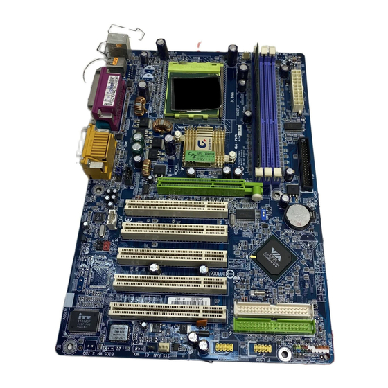
Page 13: Ga-7Va Motherboard Layout
GA-7VA Motherboard Layout RAM_LED KB_MS SOCKET A NB_FAN KT400 BATTERY PCI1 AC97 PCI2 SPDIF_IN SPDIF VT8235 PCI3 PCI4 IDE2 PCI5 IDE1 IT8705 F_PANEL BIOS F_USB1 F_USB2 PWR_LED USB 2.0 - 7 - Introduction... -
Page 14: Chapter 2 Hardware Installation Process
Step 5- Connect ribbon cables, cabinet wires, and power supply Step 6- Setup BIOS software Step 7- Install supporting software tools Step 2 Step 3 Step 5 Step 5 Step 1 Step 4 Step 5 GA-7VA Motherboard - 8 -... -
Page 15: Step 1: Install The Central Processing Unit (Cpu)
Step 1: Install the Central Processing Unit (CPU) Step1-1: CPU Speed Setup The system bus frequency can be switched at 100/133/166MHz by adjusting system switch (SW1). (The internal frequency depend on CPU.) O: ON / X :OFF Default Setting: 100MHz CPU CLOCK 100MHz 133MHz 166MHz... -
Page 16: Step1-2: Cpu Installation
M Please make sure the CPU type is supported by the motherboard. M If you do not match the CPU socket Pin 1 and CPU cut edge well, it will cause improper installation. Please change the insert orientation. GA-7VA Motherboard - 10 -... -
Page 17: Step1-3:Cpu Heat Sink Installation
Step1-3:CPU Heat Sink Installation 2. Use qualified fan approved by AMD. 1. Press down the CPU socket lever and finish CPU installation. 3. Fasten the heatsink supporting-base 4. Make sure the CPU fan is onto the CPU socket on the main- plugged to the CPU fan connector, board. -
Page 18: Step 2: Install Memory Modules
M When STR/DIMM LED is ON, do not install/remove DIMM from socket. M Please note that the DIMM module can only fit in one direction due to the one notches. Wrong orientation will cause improper installation. Please change the insert orientation. GA-7VA Motherboard - 12 -... -
Page 19: Step 3: Install Expansion Cards
DDR Introduction Established on the existing SDRAM industry infrastructure, DDR (Double Data Rate) memory is a high performance and cost-effective solution that allows easy adoption for memory vendors, OEMs and system integrators. DDR memory is a sensible evolutionary solution for the PC industry that builds on the existing SDRAM i n frastructure, yet makes awesome advances in solving the system perf o rmance bottleneck by doubling the memory bandwidth. -
Page 20: Step 4: Connect Ribbon Cables, Cabinet Wires, And Power Supply
Also make sure your OS supports USB USB 1 controller. If your OS does not support USB USB 0 controller, please contact OS vendor for possible patch or driver upgrade. For more information please contact your OS or device(s) vendors. GA-7VA Motherboard - 14 -... -
Page 21: Audio Connectors
w Parallel Port ,VGA port and Serial Ports (COMA) Ø This connector supports 2 standard COM ports and 1 Parallel Port Parallel port. Device like printer can be connected to (25 pin Female) Parallel port ; mouse and modem etc can be connected to Serial ports. -
Page 22: Step4-2: Connectors Introduction
1) CPU_FAN 10) BATTERY 2) SYS_FAN 11) F_AUDIO 3) NB_FAN 12) SUR_CEN 4) ATX_POWER 13) CD_IN 5) IDE1/IDE2 14) AUX_IN 6) FDD 15) SPDIF 7) RAM_LED 16) SPDIF-IN 8) PWR_LED 17) F_USB1/F_USB2 9) F_PANEL 18) CI GA-7VA Motherboard - 16 -... - Page 23 Ø 1)CPU_FAN (CPU FAN Connector) Please note, a proper installation of the CPU cooler is essential to prevent the CPU from running under abnormal condition or damaged by overheating.The CPU fan connector supports Max. current up to 600 mA. 2)SYS_FAN (System FAN Connector) Ø...
- Page 24 Ø PWR_LED is connect with the system power 8)PWR_LED indicator to indicate whether the system is on/off. It will blink when the system enters suspend mode. If you use dual color LED, power LED will turn to another color. GA-7VA Motherboard - 18 -...
-
Page 25: Battery
9)F_PANEL (2x10 pins connector) HD (IDE Hard Disk Active LED) Pin 1: LED anode(+) (Blue) Pin 2: LED cathode(-) SPK (Speaker Connector) Pin 1: VCC(+) (Amber) Pin 2- Pin 3: NC Pin 4: Data(-) RES (Reset Switch) Open: Normal Operation (Green) Close: Reset Hardware System PW (Soft Power Connector) - Page 26 Ø The SPDIF output is capable of provi d ing digital audio to external speakers or compressed AC3 data to an external Dolby Digital Decoder. Use this feature only when your stereo system has SPDIF OUT digital input function. GA-7VA Motherboard - 20 -...
- Page 27 16)SPDIF_IN Ø Use this feature only when your device has digital output function. SPDIF IN 17)F_ USB1 / F_USB2 Ø Be careful with the polarity of the front USB (Front USB Conn ector, Yellow ) connector. Check the pin assignment while you connect the front USB cable.
- Page 28 GA-7VA Motherboard - 22 -...
-
Page 29: Chapter 3 Bios Setup
BIOS Setup BIOS Setup is an overview of the BIOS Setup Program. The program that allows users to modify the basic system configuration. This type of information is stored in battery-backed CMOS RAM so that it retains the Setup information when the pow er is turned off. ENTERING S ETUP Aft e r pow er on the computer, pressing <Del>... -
Page 30: The Main Menu (For Example: Bios Ver. :F1)
This setup page includes all the items in standard compatible B IOS. Advanced B IOS Features This setup page includes all the items of A ward special enhanced features. Integrated Peripherals This setup page includes all onboard peripherals. GA-7VA Motherboard - 24 -... -
Page 31: Pc Health Status
Power Management S etup This setup page includes all the items of G reen function features. PnP/PCI Configurati ons This setup page includes all the configurations of PCI & PnP ISA resources. PC Health Status This setup page is the System auto detect Temperature, voltage, fan, speed. Frequency/Vol tag e Control This setup page is control CPU’... -
Page 32: Standard Cmos Features
F Time The times format in <hour> <minute> <second>. The time i s calcul a ted base on the 24-hour milit a ry - time cl o ck. For ex ample, 1 p.m. i s 13:00:00. GA-7VA Motherboard - 26 -... - Page 33 F IDE Primary Mas ter, S lave / Secondary Master, Slave The category identi f ies the ty pes of hard disk from dri v e C to F that has been installed in the computer. There are t w o ty pes: auto type, and manual ty pe. Manual t y pe is user-definable; Auto ty pe w hich w ill automatically detect HDD type.
-
Page 34: Base Memory
Extended Memory The BIOS determines how much extended memory is present during the P OST. This is the amount of memory located above 1 MB in the CPU’ s memory address map. GA-7VA Motherboard - 28 -... -
Page 35: Advanced Bios Features
Advanced BIOS Features CMOS Setup Utili t y -Copy right (C) 1984-2002 Aw ard Soft w are Adv anced BI O S Feat u res First Boot Dev ice [Fl o ppy] Item Help Second Boot Dev ice [HDD-0] Me n u L e v e l Third Boot Dev ice [CDROM] Boot Up Floppy Seek... -
Page 36: Boot Up Floppy Seek
AGP VGA card and a PCI VGA card on board. Set I n it Display First to PCI Slot. 8PCI Set I n it Displ a y First to AGP. (Default value) 8AGP GA-7VA Motherboard - 30 -... -
Page 37: Integrated Peripherals
Integrated Peripherals CMOS Setup Utili t y -Copy right (C) 1984-2002 Aw ard Soft w are Integrated Peripherals OnChip IDE Channel0 [Enabl e d] Item Help OnChip IDE Channel1 [Enabl e d] Menu Levelu IDE1 Conductor Cable [Auto] IDE2 Conductor Cable [Auto] AC97 Audio [Enabl e d]... -
Page 38: Onchip Ide Channel
Disabled AC97 Audio. 8Disabled FUSB 1.1 Control ler MDisable this option if you are not using the onboard U SB feature. Enabl e d USB Controller. (Default value) 8Enabled Disabl e d USB Controller. 8Disabled GA-7VA Motherboard - 32 -... - Page 39 FUSB 2.0 Control ler MDisable this option if y ou are not using the onboard USB 2.0 feature. Enabl e d USB 2.0 Controller. (Default value) 8Enabled Disabled USB 2.0 Control l er. 8Disabled F US B Keyboard S upport MWhen a USB key board is installed, please set at Enabled.
- Page 40 8Disabled Set Midi Port Address to 300. 8300 Set Midi Port Address to 330.(Defaul t Value) 8330 F Midi Port IRQ Set 5 for Midi Port IRQ. (Default value) Set 10 for Midi Port IRQ. GA-7VA Motherboard - 34 -...
-
Page 41: Power Management Setup
Power Management Setup CMOS Setup Utili t y -Copy right (C) 1984-2002 Aw ard Soft w are Pow er Management Setup ACPI Suspend Ty pe [S1(POS)] Item Help øUSB Dev i c e Wake-Up From S3 Disabled Menu Levelu Soft-Off by PWRBTN [Instant-off] AC Back Function [Soft-Off]... -
Page 42: Acpi Suspend Type
F Mouse Power On Can’ t Pow er on system by Mouse Ev ent . (Defaul t v al u e) 8Disabled Can Pow er on sy st e m by Mouse Ev ent. 8Enabled GA-7VA Motherboard - 36 -... - Page 43 F PME Event Wak e up M When set at Enabled, any PCI-PM event awakes the system from a PCI-PM controlled state. This feature requires an ATX pow er supply that provides at least 1A on the +5VSB lead. Disabled PME Ev ent Wake up funct i on. 8Disabled Enabl e d PME Ev ent Wake up function.
-
Page 44: Pnp/Pci Configurations
Auto assign IRQ to PCI 3. (Def a ult v alue) 8Auto Set 3,4,5,7,9,10,11,12,14,15 to PCI3. 83,4,5,7,9.,10,11,12,14,15 FPCI4 IRQ Ass ignment Auto assign IRQ to PCI 4. (Def a ult v alue) 8Auto Set 3,4,5,7,9,10,11,12,14,15 to PCI4. 83,4,5,7,9.,10,11,12,14,15 GA-7VA Motherboard - 38 -... -
Page 45: Pc Health Status
PC Health Status CMOS Setup Utili t y -Copy right (C) 1984-2002 Aw ard Soft w are PC Health Status Reset Case Open St a tus [Di s abl e d] Item Help Case Opened Menu Levelu VCORE 1.810V DDR Vtt 1.248V +3.3V 3.280V... - Page 46 Don’ t monitor current temperat u re.(Default v alue) 8Disabled F Fan Fail Warni ng ( CPU / SYSTEM) Don’ t monitor current fan speed. (Def a ult v alue) 8Disabled Alarm w hen stops. 8Enabled GA-7VA Motherboard - 40 -...
-
Page 47: Frequency/Voltage Control
Frequency/Voltage Control CMOS Setup Utili t y -Copy right (C) 1984-2002 Aw ard Soft w are Frequency/Voltage Control Spread spect r um Modulated [Auto] Item Help CPU Host Cl o ck Control [Disable] Menu Levelu øCPU Host Frequency (MHz) øPCI / AGP Frequency (MHz) 33/66 DRAM Cl o ck(MHz) [By SPD]... - Page 48 Increase DRAM v ol t age may get stabl e for Ov er_Clock. But i t may damage t o DRAM module w hen enable t h is feature. Supply v olt a ge as DRAM module reguired. (Def a ult v alue) 8Normal Set DIMM v ol t age from 2.6V~2.8V. 8+0.1V~+.03V GA-7VA Motherboard - 42 -...
-
Page 49: Top Performance
Top Performance CMOS Setup Uti l ity -Copy right (C) 1984-2002 Aw ard Software }Standard CMOS Feat u res Top Performance }Adv anced BI O S Feat u res Load Fail-Safe Defaults }Integrated Peripherals Load Optimi z ed Defaults }Pow er Management Setup Set Superv i s or Password Disabled.... -
Page 50: Load Fail-Safe Defaults
F10:Sav e & Exit Setup Load Fail-Safe Defaults Figure 11: Load Fail-Safe Defaults F Load Fai l-Safe Defaul ts Fail-Safe defaults contain the most appropriate values of the system parameters that allow minimum sy stem performance. GA-7VA Motherboard - 44 -... -
Page 51: Load Optimized Defaults
Load Optimized Defaults CMOS Setup Uti l ity -Copy right (C) 1984-2002 Aw ard Software }Standard CMOS Feat u res Top Performance }Adv anced BI O S Feat u res Load Fail-Safe Defaults }Integrated Peripherals Load Optimi z ed Defaults }Pow er Management Setup Set Superv i s or Password }PnP/PCI Configurations... -
Page 52: Set Supervisor/User Password
Setup Menu. If you select “Setup” at “Security Option” in Advance BIOS Features Menu, you will be prompted only w hen you try to enter Setup. GA-7VA Motherboard - 46 -... -
Page 53: Save & Exit Setup
Save & Exit Setup CMOS Setup Uti l ity -Copy right (C) 1984-2002 Aw ard Software }Standard CMOS Feat u res Top Performance }Adv anced BI O S Feat u res Load Fail-Safe Defaults }Integrated Peripherals Load Optimi z ed Defaults }Pow er Management Setup Set Superv i s or Password }PnP/PCI Configurations... -
Page 54: Exit Without Saving
F10:Sav e & Exit Setup Abandon all Data Figure 15: Ex it Wit h out Sav ing Type “Y” will quit the Setup Utility without sav ing to RTC CMOS. Type “N” w ill return to Setup Utility. GA-7VA Motherboard - 48 -... - Page 55 - 49 - BIOS Setup...
- Page 56 GA-7VA Motherboard - 50 -...
-
Page 57: Chapter 4 Technical Reference
Chapter 4 Technical Reference Block Diagram CPUCLK+/- (100/133/166MHz) AMD-K7 AGP 2X/4X/8X Sy stem Bus100/133/166 MHz AGPCLK 100/133/166 MHz (66MHz) DDR RAM HCLK+/- (100MHz) VT8377 MCHCLK (100/133/166MHz) 5 PCI 66 MHz 33 MHz 14.318 MHz 48 MHz BIOS VT8235 Game Port Fl o ppy IT8705 LPT Port... -
Page 58: Bios Flash Procedure
(1) With an available floppy disk in the floppy drive. P lease leav e the diskette "UN-write protected" ty pe. Double click the "My Computer" icon from Desktop, then click "3.5 diskette (A)" and right click to select "Format (M)" GA-7VA Motherboard - 52 -... - Page 59 (2) Select the "Quick (erase)" for Format Ty pe, and pick both "Display summary when finished" and "Copy system files", after that press "Start". That w ill format the floppy and transfer the needed system files to it. Beware: This procedure will erase all the prior data on that floppy, so please proceed accordingly.
- Page 60 STEP 3: Download BIOS and BIOS utility program. (1) Please go to Gigabyte w ebsite http: //www.gigabyte.com. tw/index. html, and click "Support". (2) From Support zone, click the " Motherboards BIOS & Drivers". GA-7VA Motherboard - 54 -...
- Page 61 (3) We use GA-7VTX motherboard as example. P lease select GA-7V TX by Model or Chipset optional menu to obtain BI OS flash files. (4) Select an appropriate BI OS version (For ex ample: F4), and click to dow nload the file. It will pop up a file download screen, then select the "Open this file from its current location"...
- Page 62 (5) At this time the screen shows the following picture, please click "Extract" button to unzip the files. (6) Please extract the dow nload files into the clean bootable floppy disk A mentioned in STE P 2, and press "Extract". GA-7VA Motherboard - 56 -...
- Page 63 STEP 4: Make sure the system w ill boot from the floppy disk. (1) Insert the floppy disk (contains bootable program and unzip file) into the floppy drive A. Then, restart the system. The system will boot from the floppy disk. Please press <DEL> key to enter BIOS setup main menu when system is boot up.
- Page 64 ESC: Quit hifg : Select Item (Shi f t)F2 : Change Color F5: Old Values F6: Load BIOS Defaults F7: Load Setup Defaults F10:Sav e & Ex it Save Data to CMOS & Ex it SETUP GA-7VA Motherboard - 58 -...
- Page 65 STEP 5: BIOS flashing. (1) After the system boot from floppy disk, type "A: \> dir/w" and press "Enter" to check the entire files in floppy A. Then type the "BIOS flash utility" and "BIOS file" after A:\>. In this case you have to type "A :\>...
- Page 66 Are you sure to flash the BIOS? [Enter] to continue Or [Esc] to cancel? (4) The BIOS flash completed. Please press [ES C] to exit Flash Utility. EXIT? [Enter] to continue Or [Esc] to cancel? GA-7VA Motherboard - 60 -...
- Page 67 STEP 6: Load BIOS defaults. Normally the system redetects all devices after BIO S has been upgraded. Therefore, we highly recommend reloading the BIO S defaults after B IOS has been upgraded. This important step resets everything after the flash. (1) Take out the floppy diskette from floppy drive, and then restart the system.
- Page 68 (Shi f t)F2 : Change Color F5: Old Values F6: Load BIOS Defaults F7: Load Setup Defaults F10:Sav e & Ex it Save Data to CMOS & Ex it SETUP (4) Congratulate you have accomplished the BIOS flash procedure. GA-7VA Motherboard - 62 -...
- Page 69 Method 2: Q-Flash Introduction A. What is Q-Flash Utility? Q-Flash utility is a pre-O.S . BIOS flash utility enables users to update its BIOS w ithin BIOS mode, no more fooling around any OS. B. How to use Q-Flash? a. After power on the computer, pressing <Del> immediately during POST (Power On Self Test) it will allow you to enter AWARD BIOS CMOS SETUP, then press <F8>...
- Page 70 Are you sure to update BIOS? [Enter] to contiune Or [ESC] ot abort... !Press Enter to Run. !! COPY BIOS Completed -Pass !! Please press any key to continue Congratulation! You have completed the flashed and now can restart system. GA-7VA Motherboard - 64 -...
- Page 71 Method 3: If you don’ t have DOS boot disk, we recommend that you used Gigabyte @BIOS program to flash BIOS. Press "Tools" icon. 2.Click "@BIOS Writer v1.08q". 1.Click "Gigabyte Utilities". Click here. Click "P". 3. Please select @BIOS sever site, then Click "OK".
- Page 72 In method I, if the BIOS file you need cannot be found in @BIOS server, please go onto Gigabyte's web site for downloading and updating it according to method II. d. Please note that any interruption during updating will cause sy stem unbooted...
-
Page 73: Bios Introduction
BIOS directly. Or you may want to keep a backup for your current BIOS, just choose “Save Current BIO S” to save it first. You make a wise choice to use Gigabyte, and @BIOS update y our BIOS smartly. You are now worry free from updating wrong BIOS, and capable to maintain and manage y our BIOS easily. -
Page 74: Easy Tune
/ AGP / Memory working frequency in small increments to get ultimate system performance. It oper- ates in coordination with Gigabyte motherboards. Besides, it is different from other traditional over- clocking methods, EasyTune 4 doesn't require users to change neither B IOS nor hardware sw itch/ jumper setting;... -
Page 75: 4-/6-Channel Audio Func Tion Introduction
Revision History 2-/4-/6-Channel Audio Function Introduction The installation of windows 98S E/2K/ME /XP is very simple. Please follow next step to install the function! Ster eo Speakers C onnection and Settings: We recommend that y ou use the speaker w ith amplifier t o acquire the best sound effect if the stereo output is appl i ed. - Page 76 Di s abl e “Only SURROUND-KIT”, and press “OK”. When the “Env ironment sett i ngs” is “None”, the sound w oul d be performed as stereo mode (2 channels output). Please select the other settings for 4 channels output. GA-7VA Motherboard - 70 -...
- Page 77 Basic 6 Channel Analog Audio Output Mode Use the back audio panel t o connect the audio output w ithout any additional module. STEP 1 : Line Out Connect t h e front channel s to “Line Out”,the rear chan- Line In nels to “Line In”, and the Center/Subw oofer channels to “MIC In ”...
- Page 78 6 channel output, Line In and MIC at the same ti m e. "SURROUND-KIT" is i n cluded in the GIGABYTE unique "Audio Combo Ki t " as picture. STEP 1 : Insert the “Audio Combo Kit” in the back of the case , and fix it w i t h the screw .
- Page 79 STEP 3 : Connect the front channels to back audio panel’ s “Line Out”, the rear channels to SURROUND-KIT’ s REAR R/L, and the Center/Subw oofer channels to SURROUND-KI T ’ s SUB CENTER. STEP 4 : Click the audio icon "Sound Ef f ect" from the w i n dow s tray at the bott o m of the screen.
- Page 80 PC, and fix i t w it h screw . 2. Connect SPDI F w ire to the motherboard. 3. Connect co-ax i a l or opt i cal output to the SPDIF decoder. GA-7VA Motherboard - 74 -...
- Page 81 - 75 - Memo...
- Page 82 GA-7VA Motherboard - 76 -...
-
Page 83: Chapter 5 Appendix
Revision History Chapter 5 Appendix Picture below are shown in Windows XP (CD driver version 1.0) Insert the driver CD-title that came with your motherboard into your CD-ROM driver, the driver CD-title will auto start and show the installation guide. If not, please double click the CD-ROM device icon in "My computer", and execute the setup.exe. - Page 84 8.Click "Finish" to restart computer. 7.Click "Next". B.USB Patch Driver: Enable S3 for USB Device Setup is preparing the InstallShield(R) Wizard which will guide you through the setup process. C.VIA USB2.0 Driver 1.Click "USB 2.0 Host Controller”. 2.Click "Yes". GA-7VA Motherboard - 78 -...
- Page 85 Print to File : Press this button, you can view file on the screen . We recommand you do it. If t here is any problem occurred during USB2.0 dev ice ins talling, using or upgrading. Please v isit Microsoft or GIGABYTE website f or downloading the latest drivers.
- Page 86 CD-title will auto start and show the installation guide. If not, please double click the CD-ROM device icon in "My computer", and execute the setup.exe. Press "Audio" icon. 2.Click "Next". 2.Click "Next". 1.Click "RealTek AC’ 97 Audio Driver". 3.Click "Finish" to restart computer. 3.Click "Finish" to restart computer. GA-7VA Motherboard - 80 -...
- Page 87 CD-title will auto start and show the installation guide. If not, please double click the CD-ROM device icon in "My computer", and execute the setup.exe. Press "Tools" icon. 2.Click "Easy Tune 4 (Trial Version) 1.Click "Gigabyte Utilities". 3.Click "Next". 4.Click "Next". 5.Click "Finish" to restart computer.
- Page 88 Electrostatic Discharge Floppy Disk Device Front Side Bus Hard Disk Device Integrated Dual Channel Enhanced Interrupt Request Input / Output IOAPIC Input Output Advanced Programmable Input Controller Industry Standard Architecture Local Area Network to be continued..GA-7VA Motherboard - 82 -...
- Page 89 Acronyms Meaning Logical Block Addressing Light Emitting Diode Megahertz MIDI Musical Instrument Digital Interface Memory Translator Hub Memory Protocol Translator Network Interface Card Operating System Original Equipment Manufacturer PCI A.G.P. Controller POST Power-On Self Test Peripheral Component Interconnect RIMM Rambus in-line Memory Module Special Circumstance Instructions SECC Single Edge Contact Cartridge...
- Page 90 Model name/Lot Number: PCB revision: BIOS version: O.S./A.S.: Hardware Mfs. Model name Size: Driver/Utility: Configuration Memory Brand Video Card Audio Card CD-ROM / DVD-ROM Modem Network AMR / CNR Keyboard Mouse Power supply Other Device Problem Description: GA-7VA Motherboard - 84 -...
- Page 91 W942508BH-5 2260D Winbond Winbond 256MB W942508BH-5 2110A Winbond Winbond 256MB W942508BH-5 2150D ADATA Winbond 256MB W942508BH-5 2260D APACER Winbond 256MB W942508BH-5 2260D MShould you need to find new support list, pls refer to http://www.gigabyte.com.tw for the detail. - 85 - Appendix...
-
Page 92: Troubleshooting
Failure has been ex cluded. Check if the memory install properly into the DIMM slot. Failure has been ex cluded. Insert the VGA card. Then plug in ATX power cable and turn on the system. GA-7VA Motherboard - 86 -... - Page 93 Failure has been ex cluded. If the above procedure unable to solve your problem, please contact with your local retailer or national distributor for help. Or, you could submit your question to the service mail via Gigabyte website technical support zone (http://www.gigabyte.com.tw).
- Page 94 GA-7VA Motherboard - 88 -...
- Page 95 - 89 - Memo...
- Page 96 GA-7VA Motherboard - 90 -...
Need help?
Do you have a question about the GA-7VA and is the answer not in the manual?
Questions and answers