Table of Contents
Advertisement
Advertisement
Table of Contents

Related Manuals for Luxman 7.1 Channel Reciever LR-8500


Summary of Contents for Luxman 7.1 Channel Reciever LR-8500
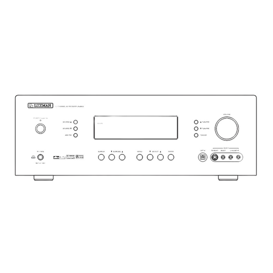
- Page 1 LR-8500 7.1 CHANNEL AV RECEIVER OWNER'S MANUAL...
-
Page 2: Important Safety Instructions
Important Safety Instructions IMPORTANT(for U.K.Customers) DO NOT cut off the mains plug from this equipment. If the plug fitted is not suitable for the power points in your home or the cable is too short to reach a power point, then obtain an appropriate safety approved extension lead or consult your dealer. -
Page 3: Table Of Contents
Thanks for choosing LUXMAN. Read this manual carefully to get the best performance from this unit. Before Use ...4 Description...5 Connections...6 - Speakers, PRE OUT, AC OUTLET, RS-232C ...8 - Audio Components...9 - Video Components ...10 - Advanced Connecting ...11 - Antennas...12 Control Functions...13 Basic Operations ...17... -
Page 4: Before Use
Read this before operation < As the unit may become warm during operation, always leave sufficient space above the unit for ven- tilation. < The voltage supplied to the unit should match the voltage as printed on the rear panel. If you are in any doubt regarding this matter, consult an electrician. -
Page 5: Description
DTS was introduced in 1994 to provide 5.1 channels of dis- crete digital audio into home theater systems. DTS brings you premium quality discrete multi-channel digi- tal sound to both movies and music. DTS is a multi-channel sound system designed to create full range digital sound reproduction. -
Page 6: Connections
Description Dolby Digital identifies the use of Dolby Digital audio coding for such consumer formats as DVD and DTV. As with film sound, Dolby Digital can provide up to five full-range chan- nels for left, center, and right screen channels, independent left and right surround channels, and a sixth ( ".1") channel for low-frequency effects. -
Page 7: Connecting A Subwoofer
Surround back speakers Surround back speakers are required when a full 7.1-chan- nel system is installed. Speakers should be placed on a rear wall, behind the lis- tening position. The center of the speaker should face into the room. Subwoofer We recommend using a subwoofer to have maximum bass effect. -
Page 8: Speakers, Pre Out, Ac Outlet, Rs-232C
SPEAKERS, PRE OUT, AC OUTLET, RS-232C (OPTIONAL) POWERED SUBWOOFER ZONE II AUDIO OUTPUT RC-232C RIGHT RIGHT RIGHT FRONT ZONE II SPEAKER OUTPUTS Surround Back/ZONE II Speaker Outputs: These speaker terminals are normally used to power the surround back left/surround back right speakers in a 7.1-channel system. -
Page 9: Audio Components
AUDIO COMPONENTS CD PLAYER AUDIO DIGITAL The output audio signal from the TAPE OUT jack is the same signal which is currently selected. Caution: • Do not connect this unit and other components to mains power until all connections between components have been completed. -
Page 10: Video Components
VIDEO COMPONENTS DVD PLAYER AUDIO COMPONENT VIDEO OUT DIGITAL VIDEO, S-VIDEO , COMPONENT JACKS There are 3 types of video jacks on the rear panel. VIDEO jack The video signal for the VIDEO jacks is the conventional com- posite video signal. S-VIDEO jack The video signal is separated into luminance (Y) and color (C) signals for the S-VIDEO jack. -
Page 11: Advanced Connecting
VIDEO COMPONENTS AND ADVANCED CONNECTING SATELLITE TUNER AUDIO REMOTE IR IN/OUT PUT ZONE II IR INPUT CENTER SURR. FRONT SURR. WOOFER BACK POWER AMPLIFIER CONNECTING MULTI CHANNEL AUDIO SOURCE The 7.1 CH DIRECT INPUT jacks are for multichannel audio source such as a SACD multichannel player, DVD audio player or external decoder. -
Page 12: Assembling The Am Loop Antenna
CONNECTING THE ANTENNA TERMINALS FM antenna FM external antenna ASSEMBLING THE AM LOOP ANTENNA 1. Release the vinyl tie and take out the connection line. 2. Bend the base part in the reverse direction. 3. Insert the hook at the bottom of the loop part into the slot at the base part. -
Page 13: Control Functions
Front Panel Main Power Switch Press this button to turn the unit standby or off. Power Indicator This LED Lights amber when the unit is in the standby mode to signal that the unit is ready to be turn on, when the unit is in operation, the indicator is blue. - Page 14 Display Remote Control Unit Control Functions Illuminates when a station is tuned. STEREO indicates in the tuner mode. RDS MODE indicator SLEEP indicator Lights up when the sleep timer is active. POWER System power on and off. FUNCTION buttons Use these buttons to select function modes. Numeric buttons These buttons serve as a 10 button numeric keypad to enter tuner preset positions.
- Page 15 SURR (v/^) Press this button to select from among the available surround mode options for the mode group selected. - Press to select CHANNEL LEVEL. (AMP only) TOP MENU - Press to call up the top menu. (DVD only) DIRECTION - Use to more through the options on menu screens.
- Page 16 DELAY - Press this button to begin the process for setting the delay times used LR-8500 when processing surround sound or to compensate for video-to-audio delays caused by the use of digital sources or video displays. SET UP - Enter or exit the system setup menu. (DVD only) ENTER Press to enter setting.
-
Page 17: Basic Operations 1
Control Functions is connected to the ZONE II IR Input jack, this button will raise or lower the volume in the remote room. INPUT Selectors When the LR-8500 is off, press one of these buttons to select a specific input and turn the unit on. When the unit is already in use, pressing one of these buttons will change the input. - Page 18 STANDBY/ON SELECT SOURCE SURROUND MODE MENU ENTER GROUP SELECTOR SURROUND MODE SELECTOR SOURCE (6/n ) Press to select input sources. VOLUME knob To control the overall listening level, turn the MASTER VOL- UME knob or press the VOLUME buttons (+/–) on the remote control unit.
-
Page 19: Surround Mode
Surround Mode One of the most important features of the LR-8500 is its ability to reproduce a full multichannel surround sound field from digital sources, analog matrix surround- encoded programs and standard stereo programs. Surround modes may be changed at any time by using either the front panel or remote controller. -
Page 20: Zone Ii Operation
When operation the LR-8500 from a remote room loca- tion where an IR sensor link has been connected to the LR-8500's rear-panel IR Input you may use ZONE II either the main remote control or the ZONE II remote controller. To activate the feed to the remote room, while you are main listening room where the LR-8500 is located, Press the MULTI button on the main remote con-... -
Page 21: Speaker Configuration
SPEAKER FRONT SMALL CENTER SMALL SURR SMALL SBACK SIZE SPEAKER SPEAKER SPEAKER SPEAKER LARGE LARGE LARGE NONE NONE FRONT L 9.0 M CENTER 9.0 M FRONT R 9.0 M SPEAKER FRONT L FRONT L 0.0 M CENTER CENTER 0.0 M FRONT R FRONT R 0.0 M SURR R DELAY DISTANCE... - Page 22 VOLUME TEST-T ENTER DELAY Input the distance from your listening position Press the DELAY button to "FRONT L DISTANCE" appears on the front panel's display. Press the ENTER button. "FRONT" appears on the display. Press the t button. "FRONT L 3.O M" appears on the display. Press the buttons to change the setting.
-
Page 23: Tuner Operation
TUN/PRE SELECT SOURCE AM/FM T.MODE The LR-8500's tuner is capable of tuning AM, FM and FM Stereo broadcast stations. Stations may be tuned manually, or they may be stored as favorite station presets and recalled from a 50-position memory. Station Selection Press the AM/FM button on the remote controller to select the tuner as an input The tuner may be selected from the front panel by either... -
Page 24: Rds
RDS (Radio Data System) (Remote Controller Only) RDS is a broadcasting service which allows stations to send additional information along with the regular radio program signal. RDS can be received only in FM band. Every time the RDS button is pressed, the mode is changed as follows: PS (Program Service Name) When you select PS, "PS"... -
Page 25: Video Operations
Video Operations Playing Video Sources Note: When playing videos that feature surround sound, refer to "Available Surround Modes". Select the DVD, VIDEO 1, VIDEO 2, AUX 1, AUX 2 mode by pressing the SOURCE button (6/n) Play the component corresponding to the FUNCTION selected. -
Page 26: Function Setup
FUNCTION SETUP FUNCTION SETUP INPUT FUNC : DIGITAL IN : ANALOG DIGITAL POLLING : BACK TO MAIN MENU You can select associate one of the digital inputs with the selected input source. Some digital video input sources, such as a cable box or HDTV set-top, may change between analog and digital outputs, depending on which channel is in use. -
Page 27: Dolby Surround
Theater The Theater mode creates a sound field that resembles the acoustic feeling of a standard live-performance theater. Hall 1, Hall 2 The two Hall modes create sound fields that resemble a small (Hall 1) and medium-sized (Hall 2) concert hall. 5-Channel Stereo, 7-Channel Stereo This mode takes advantage of multiple speakers to place a stereo signal at both the front and back of a room. -
Page 28: Speaker Setup
In normal use, this feature is turned off, which means that digital sources are processed at their native sample rate. For example, a 48kHz digital source will be processed at 48kHz. However, the LR-8500 allows you to upsample the incoming 48kHz signals to 96kHz for added resolution. NOTE: This feature is only available for the Dolby Pro Logic ll-Music, Dolby Pro Logic ll-Movie, Dolby Pro Logic and Dolby 3 Stereo modes. -
Page 29: Distance Adjust
no adjustments are needed and you may skip this section. However, should you wish to change one of the settings. The available choices at which point low-frequency infor- mation will be sent to the subwoofer, rather than to the main speaker channel, are 40Hz, 60Hz, 80Hz, 100Hz, 120Hz and 200Hz. -
Page 30: Zone Ii Setup
video display screen whenever the volume, input source, surround mode, tuner frequency or any of the configura- tion settings are changed. Set to change the length of time that the semi-OSD dis- plays remain on the screen. • FULL OSD TIME OUT The full-OSD menu system is used to simplify the setup and adjustment of the LR-8500, using a series of on screen menus. - Page 31 System Configuration phone is firmly connected. The microphone cable is approximately 6 m long, which should accommodate most listening room situations. If required, you may use an optional extension cable, available at most electronics stores, for use in larger rooms. However, we recommend that you avoid using extension cords for the microphone cable, as they may adversely affect the test results.
- Page 32 During this test, you will see a message in the last line of the menu screen change as the volume level is adjusted. • Speaker Check: The system will circulate a test signal to determine which channels have a speaker connected. During this test, you will see the name of each channel position displayed while a signal is sent to that speaker.
-
Page 33: Controlling Other Components Connected To The Lr-8500
Controlling other Components Connected to the LR-8500 The LR-8500 is equipped with a powerful remote control not only receiver's functions, but also most popular brands of audio and video equipment, including CD players, cassette decks, TV sets, cable boxes, VCRs, satellite receivers and other home theater equipment. -
Page 34: Programming The Remote
Programming the Remote VCR Brand List Brand CODE No. AKAI ALBA AMSTRAD ANITSCH ARC EN CIEL ARISTONA AWIA BAIRD BAUER. BOSCH BLAUPUNKT BRANDT ELECTRONIQUE BRIONVEGA BUSH C.EDISON CANON CAPEHART CONTINENTAL EDISON CRAIG CURTIS MATHES DAEWOO DAYTRON DECCA DEGRAAF DUAL DUMONT DYNATECH EMERSON FERGUSON... - Page 35 Programming the Remote VCR Brand List Brand CODE No. SAISHO SALORA SAMSUNG SANSUI SANYO SCHAUB LORENZ 041 SCHNEIDER SEI-SINUDYNE SELECO SENTRA SHARP SHINTOM SIEMENS SIERA SINUDYNE SONY STERN SUNKAI SYLVANIA SYMPHONIC TASHIKO TATUNG TEAC TEKNIKA TELEAVIA TELEFUNKEN TENOSAL THOMSON THORN- FERGUSON TOSHIBA TOTELEVISION...
- Page 36 Programming the Remote SAT Brand List Brand CODE No. PHILIPS PHONOLA PROSAT QUADRAL QUELLE RADIOLA REDIFFUSION SABA SALORA SAMSUNG SAT PARTNER SATPORTNER SCHAUB LORENZ 026 SCHNEIDER SIEMENS SIERA SILVA STARCOM STARSAT TECHNISAT TELEFUNKEN TELESYSTEM THORN- FERGUSON TRIAD UNIDEN UNITED CABLE V TECHNOLOGY VORTEC ZENDER...
- Page 37 Programming the Remote TV Brand List Brand CODE No. ERRES EUROPHON FERGUSON FIDELITY FINLUX FISHER FORGESTONE FORMENTI FORTRESS FRABA FRONTECH FUJITSU FUNAI GELOSO GOLDSTAR GOODMANS GORENJE GREATZ GRANADA GRUNDIG HANSEATIC HANTAREX HEMMERMANN HIFIVOX HINARI HITACHI HYPER IMPERIAL INGELEN INNO HIT INTERFUNK IRRADIO Brand...
- Page 38 Programming the Remote TV Brand List Brand CODE No. PATHE CINEMA PERDIO PHILCO PHILIPS PHOENIX PHONOLA PIONEER PRANDONI- PRINCE PREMIER PRINCE PROTECH QUASAR QUELLE RADIOLA RADIOMARELLI RANK REDIFFUSION ROBOTRON SABA SAISHO SALORA SAMBERS SAMPO SAMSUNG SANYO SCHAUB LORENZ 001 SCHNEIDER Brand SELECO SHARP...
-
Page 39: Troubleshooting
SYMPTOM Unit does not function when • No AC power Main Power Switch is pushed • Intermittent input connections Display lights, but no sound or picture • Mute is on • Volume control is down Unit turns on, but front-panel •... -
Page 40: Specifications
Amplifier Section Output Power Power Output (20 Hz - 20 kHz, THD<0.07%, 8 ohms) Front L&R 110 W / Ch Center 110W / Ch Surround L & R 110 W / Ch Surround Back 110 W / Ch Power Output (EIAJ, 1 kHz, 8 ohms) Front L&R 140 W / Ch Center... - Page 41 LUXMAN CORPORATION, JAPAN...
Need help?
Do you have a question about the 7.1 Channel Reciever LR-8500 and is the answer not in the manual?
Questions and answers