Garmin 20 Pilot's Manual
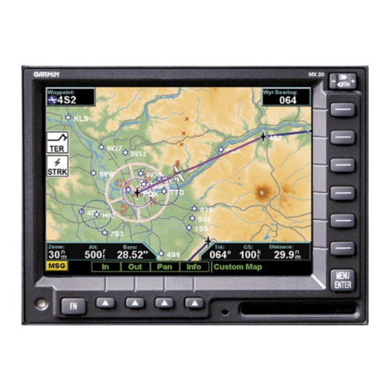
Color multi-function display
Hide thumbs
Also See for 20:
- User manual (20 pages) ,
- Set up and go manual (20 pages) ,
- Quick reference manual (2 pages)
Table of Contents
Advertisement
Quick Links
Advertisement
Table of Contents
Troubleshooting

Related Manuals for Garmin 20


Summary of Contents for Garmin 20
- Page 1 MX20 color Multi-Function Display pilot’s guide...
- Page 2 All rights reserved. Except as expressly provided herein, no part of this manual may be reproduced, copied, transmitted, disseminated, downloaded or stored in any storage medium, for any purpose without the express prior written consent of Garmin. Garmin hereby grants permission to download a single copy of this manual onto a hard drive...
-
Page 3: History Of Revisions
560-1026-09 Rev A Ordering Information To receive additional copies of this MX20 Pilot’ s Guide, order part #560-1026-09 Rev A (Garmin P/N 190- 00479-00 Rev D). The MX20 Installation Guide is part #560-1025-xx. The MX20 Quick Reference Guide is part #561-0263-xx. - Page 4 > You may use the SOFTWARE only on the MX20. > Restricted Functionality. You are licensed to use the SOFTWARE to provide only the limited functionality (specific tasks or processes) for which the MX20 has been designed and marketed by Garmin. This license specifically prohibits any other use of the software programs or functions, or inclusion of additional software programs or functions that do not directly support the limited functionality on the MX20.
- Page 5 SOFTWARE. > Product Support. Product support for the SOFTWARE is not provided by MS, Microsoft Corporation, or their affiliates or subsidiaries. For product support, please refer to Garmin’ s support number provided in the documentation for the MX20. Should you have any questions concerning this EULA or if you desire to contact Garmin for any other reason, please refer to the address provided in the documentation for the MX20.
-
Page 6: Accessories And Packing List
Introduction Welcome… Welcome to a new era of aviation navigation. Once again, Garmin has set new standards in features and ease Accessories and Packing List of use for the general aviation public. The MX20 Multi-Function Display provides a focal point for integrating many of your navigation needs in an easy to use and convenient package. -
Page 7: Limitations
Introduction Limitations Limitations The Traffic function is not a collision avoidance system. It is an aid to visual acquisition and does not relieve the flight crew of their responsibility to “see and avoid.” There are no evasive aircraft maneuvers authorized, recommended, or provided for as a result of displayed traffic targets. -
Page 8: Table Of Contents
Auto Zoom ............19 Airport Chart ............ 27 ADS-B Traffic ..........6 Map Scale ............19 Terrain .............. 27 Skywatch/TCAD/TIS-A Traffic ....... 6 Pan ..............20 Obstructions ............. 28 Terrain ............6 Info ..............20 Traffic ..............28 Lightning ............6 Info In Pan Mode .......... - Page 9 Introduction Table of Contents Map Orientation ..........30 TAS Time-Out ..........38 Ident (GDL 90 UAT only) ......46 Invert ..............31 No Bearing Advisories ........38 Confirm Code ..........47 Nav Data ............31 TAS Menu Options ..........38 Operation ............
- Page 10 Introduction Table of Contents Symbology ............53 Menu Options for Overlay Page 2 ....64 Winds Aloft Altitude ........74 Traffic Status Indicators ........54 Label ............64 TFR Lbl ............74 Flight Plan (FPL) Function........55 Flight Plan ........... 64 Label ............
- Page 11 Introduction Table of Contents Radar (RADAR) Function........98 Diagnostics ..........82 Viewing the Chart as an Overlay ....... 90 Activation ............ 82 Display of Coverage Area ......90 Off Mode ............. 99 Activating XM Radio Services ......83 Chart Zooming ..........91 Standby/On Mode ........
- Page 12 Introduction Table of Contents Garmin Data Cards ..........121 Mute ............107 Channels ............107 Installing and Removing Data Cards ....121 Specifications ............ 122 Categories ............108 Direct Access ........... 108 Physical Specifications ........122 XM Advisory Messages ........109 Power ..............
-
Page 13: Getting Started
Getting Started Functions Getting Started MX20 Functions This section explains how to get started using the MX20. Information in this section describes the controls, • MSG - Message Log data card, display, and basic operation. After reading this section, go to the Detailed Operation section for •... - Page 14 Getting Started Functions The Message Log displays information from the MX20 or reported to the MX20 by its external sensors. A flashing MSG annunciator notifies you of a new message that should be viewed. The Custom Map function allows you to completely customize the displayed map by overlaying selected information.
-
Page 15: Controls
Getting Started Controls Controls Power/Brightness Two variations of the Power/Brightness control exist, a rotary knob or a rocker switch. Both are described here. Power Rotary Switch The power switch is located in the upper right corner of the MX20. Turn the power rotary knob clockwise past the detent to turn the power on. -
Page 16: Menu Item
When fully inserted, the data card and eject button will be flush and slightly recessed into the bezel. When contacting your dealer or the Garmin customer service department, eject the data card and write down the information shown on the label. -
Page 17: Display
Getting Started Display Display The MX20 display provides text and graphic information to give a “picture” of your flight and surroundings. The display brightness may be set manually or allowed to automatically adjust to ambient light conditions. At the bottom of the display, labels above the function keys change to show the different choices for each function to allow access to commonly used actions. -
Page 18: Annunciations
Getting Started Annunciations Annunciations Advisory flags, data flags, and messages appear on the display to give information about the status of the MX20 or to provide operating information. Advisory Flags Annunciations will appear on the upper left side of the display to provide advisories for Traffic, Terrain, and Lightning. -
Page 19: Message Flag
Getting Started Data Flags Data Flags Data flags appear on the left side of the display to notify you when there is a loss of reported information. Message Flag The data usually displayed, such as lightning or nearby terrain, may still exist, but may not be displayed for The Message flag will appear on the technical reasons. - Page 20 Getting Started Data Flags Data Flag Description Terrain coverage is not available for some part of the terrain advisory coverage area. Terrain advisories may not be provided. When connected to the SL30, indicates the SL30 is not avail- able or valid. ILS, OBS, and VORs will not be highlighted. No valid traffic information is being received from the optional Ryan TCAD sensor.
-
Page 21: Basic Operation
Getting Started Basic Operation Basic Operation Use the following items to get a basic feel for the operation of the MX20. The basic steps for using any of the Power On separate functions of the MX20 are: Turn the power rotary knob clockwise past the •... -
Page 22: Start Up Screen
Getting Started Start Up and Baro Correction Start Up Screen The Start Up screen is displayed while the MX20 goes through its initialization and testing routines. System information is shown that provides the MX20 software and database versions. The results of the self test are shown. -
Page 23: Function Selection
Getting Started Function Selection Function Selection Press the FN key to view the different Functions. The functions are shown above the function “smart” keys on the lower part of the display in blue. Press the function key under the function label to activate that function. The labels above the function key will change to reflect the custom “smart”... -
Page 24: Advisory Hot Key
Getting Started Advisory Hot Key Advisory Hot Key The “Advisory Hot Key” feature allows advisory conditions to be quickly viewed with minimal effort by the pilot. This feature is comprised of three components: 1) An advisory condition is indicated by a white advisory flag on the left side of the screen and the corresponding Function label will also be highlighted in white when selecting a new Function with the FN key. -
Page 25: Alert Hot Key
Getting Started Alert Hot Key, Options, Thumbnail Alert Hot Key Traffic alerts go one step further than the Advisory hot key feature and will automatically bring up the Func- tion Menu showing the Traffic function. This is called the “prompt” mode. A single key press can then be used to switch the display to the Traffic function. -
Page 26: Traffic On Thumbnail
Getting Started Thumbnail and TIS Traffic on Thumbnail TIS, TAS, or TCAS traffic is shown on the Thumbnail in the same symbology used within the Traffic Function. ADS- B traffic is not shown on the Thumbnail. Any traffic within sensor range and 5 nm is shown, in addition to traffic causing an amber Traffic Alert (TA) traffic. - Page 27 Getting Started Function Summary...
- Page 28 Getting Started Function Summary...
- Page 29 Getting Started Function Summary...
-
Page 30: Message Log (Msg)
Detailed Operation Message Log Message Log (MSG) The Message function displays information about the status of the MX20. Messages may be logged by either the MX20 internal system or by one of the external sensors. The amber MSG flag will flash until the message is viewed. -
Page 31: Custom Map (Map)
Detailed Operation Custom Map Custom Map (MAP) The Custom Map function provides a graphic display of map features in relation to the aircraft location to Map Scale help improve your situational awareness. Review the Limitations section in the front of this guide that apply to The In and Out function keys control the map the use of data displayed on the moving ma\p. -
Page 32: Pan
Detailed Operation Custom Map The Pan keys are used to move the display around so you can see beyond the initial boundaries of the screen. The PAN function key is one of the “smart” keys available at the bottom of the screen. When you select the Pan function, four “arrow”... -
Page 33: Info In Pan Mode
Detailed Operation Custom Map Info In Pan Mode INFO smart key supports operation in conjunction with the PAN feature. On any of the maps (Custom Map, IFR and VFR), entering the INFO mode while pan is active, will show information about the nearest airport to the center of the screen. This allows panning around the immediate area and obtaining information about airports in the vicinity without changing the current “TO”... -
Page 34: Invert
Detailed Operation Custom Map at the top of the screen and a 360° ring with the aircraft symbol position in the center. Desired Track Up sets the desired track to the next waypoint as the top of the screen. Press the MENU ITEM key next to this option to scroll through the options. -
Page 35: Custom Map Menu Option
Detailed Operation Custom Map Custom Map Menu Option Page 2 The second option page of the Custom Map function lets you select options for the choices of Airports, VORs, NDBs, Intersections, and Airspace. The last option selection takes you to the next page of options. Airports The Airports option allows you to choose the level of airport information displayed on the Map screen. -
Page 36: Vor Obs
Detailed Operation Custom Map The VOR information box for the selected VOR will show the distance and radial-from bearing between your present position and the VOR. The radial and distance information comes from your GPS, not the SL30. The MX20 must have VOR symbols turned on for this feature to be active in the Custom Map function. VOR information is always shown in the IFR and VFR Chart functions. -
Page 37: Ndbs
Detailed Operation Custom Map NDBs The NDBs option allows you to choose the type of NDB information displayed on the Map screen. You may select the display of NDB icon and identifier, icon only, or no information by each subsequent press of the NDB MENU ITEM key. -
Page 38: Custom Map Menu Option
Detailed Operation Custom Map Custom Map Menu Option Page 3 The third option page of the Custom Map function lets you select options for the choices of Low Airways, High Airways, Water, Roads, and political boundaries. The last option selection takes you to the next page of options. -
Page 39: Custom Map Menu Option
Detailed Operation Custom Map Custom Map Menu Option Page 4 The fourth option page of the Custom Map function lets you select options for choices of Airport Charts, Ter- rain, Obstructions, Traffic, and Lightning Strikes. Airport Chart Airport surface charts provide a graphical presentation of the airport surface area (runways, taxiways, build- ings, towers and other objects), within the immediate airport vicinity. -
Page 40: Obstructions
Detailed Operation Custom Map Obstructions Obstructions, such as towers and other man-made objects, are part of the MX20 updateable database. Obstruc- Obstruction icon tions over 250 feet high are shown on the maps with tower symbols. The symbol is color coded to signify the relative altitude of the tower to your aircraft’... -
Page 41: Strikes
The Strikes menu option controls the display of lightning strike information if the MX20 receives strike data from an external source, such as the WX500. Each reported lightning strike is shown as a red “x” on the display. Strikes are not shown if the zoom level is below 20 nm. Lightning strike icon (red “x”) -
Page 42: Ifr En Route (Ifr) Chart Function
Detailed Operation IFR En Route Chart IFR En Route (IFR) Chart Function The IFR En Route Chart function shows an IFR en route style map for the display. The IFR display shows navigational aid information and the flight plan course line. The “smart” keys on the bottom of the screen control zooming in and out, panning, and the display of information on the current TO waypoint. -
Page 43: Invert
Detailed Operation IFR En Route Chart Invert The Invert option changes the display of text and the background color. The Invert option switches between a white background with black text and a black background with white text. Nav Data The Nav Data option allows you to control the display of navigation data on the Map displays. Subsequent presses of the MENU ITEM key for this option provides choices of no nav data, nav data in the corners (waypoint, bearing, zoom, and distance), or full nav data. -
Page 44: Airport Chart
Detailed Operation IFR En Route Chart Airport Chart Airport surface charts provide a graphical presentation of the airport surface area (runways, taxiways, build- ings, towers and other objects), within the immediate airport vicinity. From either the Custom Map or the IFR en route Map, airport surface charts will automatically be loaded and displayed as an overlay if the following conditions are met: •... -
Page 45: Vfr Chart (Vfr) Function
Detailed Operation VFR En Route Chart VFR Chart (VFR) Function The VFR Chart function shows an VFR sectional style map for the display. Topographic features are shown. The VFR display shows navigational aid information and the flight plan course line. The “smart” keys on the bottom of the screen control zooming in and out, panning, and the display of information about the current TO waypoint. -
Page 46: Nav Data
Detailed Operation VFR En Route Chart Nav Data The Nav Data option allows to control the display of navigation data on the Map displays. Subsequent presses of the MENU ITEM key for this option provides choices of no nav data, nav data in the corners (waypoint, bearing, zoom, and distance), or full nav data. -
Page 47: Split Screen (Split) Function
Detailed Operation Split Screen Split Screen (SPLIT) Function The Split Screen capability allows you to display up to two enabled functions side by side. Press the MENU ITEM key next to the desired map to highlight the selection. When two functions are displayed, you must first deselect a highlighted selection before selecting another function. -
Page 48: Tas / Tcad Traffic (Traf) Function
Detailed Operation TAS/TCAD Traffic TAS /TCADTraffic (TRAF) Function The MX20 I/O Traffic model supports interfaces to third party traffic sensors. The traffic function, when inter- faced to the Goodrich Skywatch, the Honeywell IHAS (both referred to as TAS sensors), or the Ryan TCAD is capable of displaying traffic targets as supplied by those sensors. -
Page 49: Symbology
Detailed Operation TAS/TCAD Traffic Symbology Traffic is shown with either the relative or absolute altitude indicated above or below the target symbol. If the traffic is below or equal to your ownship altitude, the label is shown below the symbol. If the traffic is above your ownship altitude, the label is shown above the symbol. -
Page 50: Test (Skywatch)
Detailed Operation TAS/TCAD Traffic Test (Skywatch) TAS Test will be displayed if the Traffic sensor is in the Test Mode. Not Displayed An amber “Traffic Not Displayed” will be shown if the GPS position or the Traffic sensor has failed. TAS Fail System Failure, shown in amber. -
Page 51: Self-Test
Detailed Operation TAS/TCAD Traffic Self-Test When in Standby Mode, a TAS Self-Test can be initiated by selecting this option. TCAD 9900B Menu Options Altitude Option (Relative/Pressure) The Altitude option lets you select between relative and pressure altitude in hundreds of feet. The Altitude op- tion choice is shown in the upper left corner of the screen. -
Page 52: Shield Heights
Detailed Operation TAS/TCAD Traffic Shield Heights This allows the shield heights to be adjusted for the En Route, Standard, and Terminal shield modes. See the TCAD operator’ s manual for additional details. Shield Ranges This allows the shield ranges to be adjusted for the En Route, Standard, and Terminal shield modes. See TCAD operator’... -
Page 53: Ads-B Traffic (Traf) Function
Detailed Operation ADS-B Traffic ADS-B Traffic (TRAF) Function The Traffic Function allows you to view other traffic in the area, when installed with a UAT data link radio. The term “UAT” refers to the “GDL 90” UAT. This screen can also show your flight plan. Traffic is shown in relation- ship to your aircraft. - Page 54 Detailed Operation ADS-B Traffic Automatic Dependent Surveillance-Broadcast (ADS-B) is a surveillance technology being deployed in selected areas of the NAS. ADS-B broadcasts a radio transmission approximately once per second containing the aircraft’ s position, velocity, identification, and other information. ADS-B can also receive reports from other suitably equipped aircraft within reception range.
-
Page 55: Traffic Description
Detailed Operation ADS-B Traffic Additionally, UAT systems provide a VFR mode that may be used by pilots when not wanting to receive air traffic services. The “Set 1200” feature will broadcast a “VFR” ID to other aircraft and ground receivers, similar to the “1200”... -
Page 56: Tis-B Traffic
Detailed Operation ADS-B Traffic TIS-B Traffic Traffic Information Service – Broadcast (TIS-B) is supported by displaying non ADS-B equipped aircraft that are received over the UAT data link radio. Non ADS-B equipped aircraft that are detected by ground-based radar can be up-linked to all aircraft in the area that are UAT data link equipped and within the GBT service volume. As TIS target location is determined by ground based radar, coverage, range and target positional accuracy are highly dependent on relative location to the actual radar site. -
Page 57: Tis-B Limitations
Detailed Operation ADS-B Traffic TIS-B Limitations 1. TIS-B is NOT intended to be used as a collision avoidance system and does not relieve the pilot’ s responsibility to “see and avoid” other aircraft. TIS-B shall not be used for avoidance maneuvers during times when there is no visual contact with the aircraft. -
Page 58: Degraded Target
Detailed Operation ADS-B Traffic clearance based on TIS-B displayed cockpit information must be approved by the controlling ATC facility prior to commencing the maneuver. Uncoordinated deviations may place an aircraft in close proximity to other aircraft under ATC control not seen on the airborne equipment, and may result in a pilot deviation. -
Page 59: Confirm Code
Detailed Operation ADS-B Traffic Confirm Code When the MX20 starts up and you then press any function key, a pop-up will appear for you to confirm or set your aircraft FID (Flight ID). Press OK to confirm the displayed FID or press 1200 to set the FID to 1200. The FID will not be sent to the GDL 90 UAT until you confirm the FID. -
Page 60: Transmit Status
Detailed Operation ADS-B Traffic Transmit Status (ADS-B Broadcast Options - GDL 90 UAT only) Selecting Tx Alt allows ADS-B position reports to be transmitted with altitude information. Tx Alt Off removes altitude information from the ADS-B position reports. Standby suspends ADS-B position reports, but displays other aircraft data when available. -
Page 61: Enter Code (Gdl 90 Uat Only)
Detailed Operation ADS-B Traffic Enter Code (GDL 90 UAT only) This is where you enter the ATC-assigned transponder code. This code entered into the MX20 does NOT control the code on Mode A, C, or S transponders. It only sends the selected code to the GDL 90 UAT for inclusion into the position report. -
Page 62: Traffic Altitude Filter
Detailed Operation ADS-B Traffic Traffic Altitude Filter For ADS-B equipped installs, an altitude filter allows targets that are outside of a ±2000 foot vertical range to be filtered off the display. This option is controlled via the Traffic Function Menu and causes the on-screen mode to change from “ALL” to “±2000”... -
Page 63: Traffic Menu Option
Detailed Operation ADS-B Traffic Traffic Menu Option Page 3 The third menu option page of the Traffic function lets you select options for the choices of Display mode, Flight ID Editing, and Labeling. The last option selection takes you back to the first page of options. Display Mode The display mode lets you select either a graphic or text version of traffic information. -
Page 64: Tis-A Traffic (Traf) Function
The MX20 I/O supports the Traffic Information Services – Addressed (TIS-A) function when interfaced to a third party TIS-A sensor. The traffic function, when interfaced to the Garmin GTX 330 is capable of displaying traffic targets supplied by that sensor. Standard TCAS-type symbology is used and several menu options are available for adjusting traffic presentation and sensor operation. -
Page 65: Tis-A Menu Options
Detailed Operation TIS-A Traffic Targets are displayed at full brightness for the first six (0 to 6) seconds. If the TIS-A data is not refreshed, the targets will be displayed at a reduced brightness for the next six (6 to 12) seconds during an interval known as “coasting,”... -
Page 66: Traffic Status Indicators
Detailed Operation TIS-A Traffic Traffic Status Indicators The following status indicators are displayed in the lower right portion of the display: “TIS Operating” to indicate the TIS-A Sensor is operating and within TIS-A service coverage. “TIS Coasting” to indicate that the target information is between 6 and 12 seconds old. This may happen if the TIS-A sensor has missed a radar sweep. -
Page 67: Flight Plan (Fpl) Function
Detailed Operation Flight Plan Flight Plan (FPL) Function Use the Flight Plan function to view details about your flight plan route. Press the UP/DOWN arrow “smart” INFO keys to step through the waypoints in your flight plan. Press the “smart” key to view information about the waypoint. -
Page 68: Terrain (Ter) Function
Detailed Operation Terrain Terrain (TER) Function The Terrain Function shows a map of the terrain in the area relative to your airplane’ s position and altitude. The MX20 has a standard internal based terrain function. The MX20 also supports an external TAWS sensor. When the external TAWS sensor is connected, it replaces the MX20’... -
Page 69: Terrain Option Page
Detailed Operation Terrain Color Description Terrain that is within 500 feet, or above, your current altitude YELLOW Terrain that is within 1000 feet of your current altitude GREEN Terrain that is within 2000 feet of your current altitude BLACK Terrain that is more than 2000 feet below your current altitude LIGHT BLUE No terrain data is available Terrain Option Page... -
Page 70: Set Barometer
Detailed Operation Terrain Set Barometer Use the Set Barometer option to enter the correct barometric pressure for your area or adjust the current value. This option is best for making large changes. The BARO + and BARO - keys are more useful for minor correc- tions. -
Page 71: Uat Flight Information Service (Fis) Function
A cyan checkerboard pattern indicates that no data is available for area, and rainfall in that area is unknown. When weather data is received, the airborne system will display that data for 20 minutes, or until the power is cycled. If no new data has been received for a given area, the rainfall will be removed and the area will revert back to the cyan checkerboard pattern. -
Page 72: Text Display
Detailed Operation UAT - FIS Text Display FIS text messages are available on the text display and include METARs and TAFs. Messages are composed of four parts: message type, location, time, and message body. Viewing Text 1. Press the FN key and then the FIS function key when displayed. 2. -
Page 73: Wsi Inflight™ Flight Information Service (Fis) Function
Detailed Operation WSI - FIS WSI InFlight™ Flight Information Service (FIS) Function The Flight Information Service (FIS) Function allows access to graphic and text weather data messages on WSI InFlight-equipped installations. Graphical weather includes US and Canadian radar, METARs, and TAFs. You can select Graphical WX, Text, or Status information by pressing the MENU/ENTER key and then choosing the type of information with the MENU ITEM keys. -
Page 74: Graphical Weather (Wx) Display
Detailed Operation WSI - FIS Graphical Weather (WX) Display Weather radar images are available for display from the FIS sensor by selecting the Graphical WX option. A cyan cross-hatch pattern indicates no data has been received from the FIS sensor. Solid cyan areas represent areas where the ground based weather radars are unable to monitor weather. -
Page 75: Menu Options For Overlay
Detailed Operation WSI - FIS Menu Options for Overlay Page 1 1. Press the OVRL function key to allow selection of the Overlay choices when viewing the Graphical WX option. 2. Press to display menu items for the Overlay. Press to see more MENU/ENTER NEXT PAGE... -
Page 76: Temporary Flight Restrictions (Tfrs)
Detailed Operation WSI - FIS Temporary Flight Restrictions (TFRs) Temporary Flight Restrictions (TFRs) indicate areas where flight restrictions have been imposed. They are depicted as areas with reddish-brown outlines and a cross-hatch pattern. The area may also contain the TFR identifier. -
Page 77: Legend
Detailed Operation WSI - FIS Legend Press MENU/ENTER key and then press the LEGEND Menu Item key to display the legends describing the graphic display colors. Press the LEGEND Menu Item key once to display a legend for the Metar, Weather, and Radar colors. -
Page 78: Text Display
Detailed Operation WSI - FIS Text Display FIS text messages are available on the text display and include METARs, TAFs, AIRMETs, SIGMETs, and TFRs. Individual text messages are updated every five minutes and composed of four parts: message type, location, time and message body. -
Page 79: Smart Key Function
Detailed Operation WSI - FIS Using this interface, the pilot can easily select the desired message type (such as METAR), then select the airport of interest (such as KPDX), then select a specific METAR report by time (such as 141512Z). At all times, the message displayed in the upper FIS Message area on the screen matches the highlighted entry in the FIS Category area below. -
Page 80: Sorting Fis Messages
Detailed Operation WSI - FIS Sorting FIS Messages Special sorting capabilities are provided for in the central “location” column. This sorting allows weather reports to be sorted by location based on different criteria. When the green Selection Pointer is located in the second column, the fourth “smart” key changes to read “Sort.”... -
Page 81: Function
Tops, NEXRAD, Winds Aloft, and (Radar) Coverage. When any of these products are displayed and the zoom level is less than 20 nm, “Map Scale Limts Wx” will be displayed in the lower right corner. GDL 69/69A FIS Menu Page 1 with NEXRAD Activated... -
Page 82: Temporary Flight Restrictions (Tfrs)
Detailed Operation GDL 69/69A - FIS Temporary Flight Restrictions (TFRs) Temporary Flight Restrictions (TFRs) indicate areas where flight restrictions have been imposed. They are depicted as areas with reddish-brown outlines. The area may also contain the TFR identifier label. The TFR identifier label includes the TFR number and upper altitude. -
Page 83: Nexrad Intensity
Detailed Operation GDL 69/69A - FIS NEXRAD Intensity Colors are used to identify the different NEXRAD echo intensities (reflectivity) measured in dBZ (decibels of Z). “Reflectivity” is the amount of transmitted power returned to the radar receiver. Reflectivity (designated by the letter Z) covers a wide range of signals (from very weak to very strong). -
Page 84: Metars
Detailed Operation GDL 69/69A - FIS METARs When enabled, METARs (METeorological Aviation Reports) are shown as colored flags at airports that provide METAR reports. Press the METARs Menu Item key to enable or disable METARs. Refer to the Legend for a description of the color code. -
Page 85: Cloud Tops
Detailed Operation GDL 69/69A - FIS Cloud Tops When enabled, Cloud Tops data depicts the cloud top altitude determined from satellite imagery. Refer to the legend for a description of the Cloud Tops color coding. The update rate is every 15 minutes. Note: Cloud Tops and Echo Tops use the same color scaling to represent altitude. -
Page 86: Winds Aloft
Detailed Operation GDL 69/69A - FIS Winds Aloft The Winds Aloft selection provides the pilot with the wind speed and direction. The winds at a given altitude are selected in the Winds Aloft Alt menu item. The update rate is every 12 minutes. Winds Aloft Legend Winds Aloft Altitude The Winds Aloft selection provides the pilot with the wind speed and direction at a selected altitude from... -
Page 87: Legend
Detailed Operation GDL 69/69A - FIS Legend Press MENU/ENTER key and then press the LEGEND Menu Item key to display the legends describing the graphic display coding. 1. Press the or arrow keys NEXRAD Legend Cloud Tops Legend AIRMET/SIGMET Legend to display the legends for the selected services. -
Page 88: Map Orientation
Detailed Operation GDL 69/69A - FIS FIS Product Times Goes Blue After (Minutes) Goes Yellow After (Minutes) NEXRAD Graphical METAR Lightning Cell Movement 4.25 Radar Coverage METAR Echo Tops 10.5 Winds Aloft AIRMET SIGMET Cyclone County Warnings Freezing Level City Forecasts Cloud Tops 10.5 Map Orientation... -
Page 89: Forecast
Detailed Operation GDL 69/69A - FIS Forecast Weather forecast information is provided for an available City, SIGMETs, AIRMETs, Freezing Levels, County warnings, and Cyclones. While using this feature you can also customize the display of information showing map labels, flight plan line, legend. 1. -
Page 90: Airmet
Detailed Operation GDL 69/69A - FIS AIRMET AIRMETs (AIRman’ s METeorological Information) advises the pilot of weather that may be hazardous to single engine, other light aircraft, and Visual Flight Rule (VFR) pilots. This advisory affects an area of a least 3,000 square miles at any one time and provides data about ceiling, obscuration, and turbulence issued by the National Weather Service (NWS). -
Page 91: Cyclone
Detailed Operation GDL 69/69A - FIS Cyclone This product is not available at this time. Label Press MENU/ENTER key and then press the LABEL Menu Item key to toggle the station labels on and off. Flight Plan Press MENU/ENTER key and then press the FLIGHT PLAN Menu Item key to toggle the Flight Plan course line on and off. -
Page 92: Text
Detailed Operation GDL 69/69A - FIS Text The Text sub-function displays text messages of the available weather information. Use the function smart keys at the bottom of the display to select the message that you would like to view from the list in the FIS Category window. -
Page 93: Sorting Tafs And Metars
Detailed Operation GDL 69/69A - FIS Sorting TAFs and METARs Displayed text products can be sorted by distance from your present position (Nearest Pos), distance from destination (Nearest Dest), or alphabetically (Alpha). 1. Press Menu/Enter. 2. Press the top menu item to toggle between the choices. Temporary Flight Restrictions (TFRs) The full page view of the TFR is available when TFR Text is selected. -
Page 94: Product Status
Detailed Operation GDL 69/69A - FIS Product Status The Product Status page displays a list of all products supported by the MX20. The status is shown as available or not available. Available means the product is a part of your chosen subscription level and the MX20 has data that can be displayed. -
Page 95: Activating Xm Radio Services
Weather and/or audio data from your GDL 69/69A are provided by XM Satellite Radio, a company separate and independent from Garmin Corporation. Have your radio hardware IDs ready before contacting XM Satel- lite Radio. During the process, you can select services for subscription. Keep in mind that the GDL 69 has no audio capability, audio services will not be available with the unit. -
Page 96: Lightning Strikes (Lt) Function
25 nm to display lightning strikes. The display range is shown in the lower left corner of the display. For instance, if you zoom In to a range of 20 nm, no strikes will be shown, but if you zoom Out to 30 nm strikes will be shown. -
Page 97: Strike
Detailed Operation Lightning Strike Individual strikes are noted. Cell Only lightning strikes associated with a group, or cell, of strikes are displayed. Heading Stabilization The Heading Stabilization function of the WX500 can be turned on or off with this selection. System Data Select the System Data option to display information about the WX500. -
Page 98: Noise Monitor
Detailed Operation Lightning Noise Monitor The Noise Monitor feature is a function of the WX500. For details about using this feature refer to the WX500 owner’ s documents. The Noise Monitor displays reports of electrical noise, whether they are from lightning or other noise sources within the range of the system. -
Page 99: Chart View (Chart) Function (Optional)
Detailed Operation Chart View Chart View (CHART) Function (Optional) The optional MX20 Chart View feature provides the capability to view Jeppesen Sanderson Inc. electronic charts. Two basic types of charts can be viewed: Approach charts and airport surface charts. Approach charts can be manually loaded and overlaid on the moving map during flight, while airport surface charts are automatically overlaid while on the ground. -
Page 100: Chart Data Source
Detailed Operation Chart View Chart Data Source The same set of charts that are available in electronic form from the Jeppesen JeppView™ product are available for loading onto the MX20 platform. These consist of approaches, SIDS, STARS, airspace charts, and airport surface diagrams. -
Page 101: Chart Overlay In The Custom/Ifr Map
Detailed Operation Chart View Chart Overlay in the Custom/IFR Map On the Custom Map or the IFR En Route Map, approach charts (not airport surface charts) must be manually “loaded” as there are multiple approach charts that can apply for a given region (i.e. multiple approach charts for the same airport). -
Page 102: Loading The Approach Chart
Detailed Operation Chart View Loading the Approach Chart Once the airport is selected, the individual approach chart to be overlaid can be loaded from a list of geo-ref- erenced approach charts available for that airport. Not all approach charts can be overlaid in this fashion and only geo-referenced charts will be presented for selection from the Custom Map. -
Page 103: Chart Zooming
Detailed Operation Chart View Chart Zooming Auto zoom mode is supported from the Custom Map and is recommended to reduce the workload associated with maintaining an appropriate zoom level. In auto zoom mode (entered by zooming all the way down or all of the way up), the zoom scale will be calculated to maintain the current destination waypoint of your GPS receiver on the screen at all times. -
Page 104: Chart View Function
Detailed Operation Chart View Chart View Function The Chart View Function is accessed by pressing the FN Function key and selecting the Chart View (CHART) function. The Chart View Function incorporates five menu items that control two basic operations: • Selecting a chart (for static viewing) •... -
Page 105: Menu Items
Detailed Operation Chart View 4. View the chart. Adjust the zoom level using the IN or OUT “smart” keys. Press the PAN “smart” key and use the movement Menu Item keys on the right side of the display. Use the INFO “smart” key to step through the different details of the chart. -
Page 106: Load Current
Detailed Operation Chart View Load Current The Load Current operation allows the current (viewed) approach chart to be set as the loaded approach chart. When this operation is performed, any previously loaded chart is replaced with the chart that is cur- rently being viewed. -
Page 107: Operational Considerations
Detailed Operation Chart View charts, when viewed from the Chart View Function, the aircraft’ s ownship position is not shown on the airport surface chart. If an approach chart is currently loaded and being displayed (aircraft is in the air), it will take priority over displaying the airport surface chart. -
Page 108: Chart Notams
Detailed Operation Chart View When an approach chart is loaded and being flown, and the aircraft ground speed drops below the air/ground threshold (set from within the SYS Function), it is assumed that a landing has been performed. At this point, the loaded approach chart is automatically unloaded and the airport surface chart will be presented on the screen showing runways, taxiways, etc. -
Page 109: Typical Operational Scenario
Detailed Operation Chart View Typical Operational Scenario The following scenarios makes the assumption that: • The appropriate charts are available and geo-referenced • The default ground zoom level is set to 0.5 nm • The default air zoom level is set to “AUTO” Typical Taxi Scenario On power up and GPS position acquisition, the Custom Map Function will show the aircraft on the surface chart at a zoom level of 0.5 nm. -
Page 110: Radar (Radar) Function
Radar Radar (RADAR) Function The MX20 I/O Radar product supports an interface for the Garmin GWX 68, Allied Signal/Bendix-King ART2000/2100, and RS-181A weather radars. The GWX 68 must be installed via a separate installation approval. The GWX 68, RS-181A, and ART2000 weather radars are seamlessly integrated with the other functionality of the MX20 with a “RADAR”... -
Page 111: Off Mode
Detailed Operation Radar On initial power-up and entry to the Radar Function, the radar unit may go to the Off mode. Selections can be made to command the unit into one of the following initial modes: • STBY • ON •... -
Page 112: Map Mode
Detailed Operation Radar • Black • Green • Yellow • Red • Magenta Black is the weakest return while Magenta shows where the strongest returns were obtained. While in the weather mode (GWX 68 only), the gain can be adjusted with the Gain - and Gain + keys. MAP Mode The Map (MAP) mode is used for obtaining returns from the ground. -
Page 113: Range Control
Detailed Operation Radar Range Control The range can be adjusted using the RNG and RNG keys. Values for the radar are shown in the table below. Unit GWX 68 ART2000/2100 RS-181A Range (nm) 2.5 - 320 10 - 240 10 - 240 Tilt Control The Tilt (TILT) control is used to adjust the current tilt angle of the radar head when horizontal sweeping is... -
Page 114: Hold Control
Detailed Operation Radar ment key will show a Gain bar graph. The white reference line on the right side of the bar graph is only present in the GWX 68. Values are shown in decibels in the table below. GWX 68 ART2000/2100 RS-181A Gain (dB) -
Page 115: Radar Setup Page
Detailed Operation Radar and ±5° in vertical scanning. The Sector Scan can be moved horizontally by changing the Bearing and vertically by changing the Tilt. Radar Return Signals Interpreting radar return signals is beyond the scope of this manual. Please refer to the radar user’ s guide for details on interpreting radar data. - Page 116 Detailed Operation Radar Fault Message Description Action An irregularity with the onboard Power off the radar. The radar needs high voltage power supply. It may service. be hazardous to place the radar in transmit mode. The Automatic Frequency Control Power off the radar. The radar needs is unable to lock on to the transmit service.
-
Page 117: Xm Satellite Radio
Detailed Operation XM Satellite Radio XM Satellite Radio Audio entertainment is available through the XM Satellite Radio Service when activated in the optional installa- tion of the GDL 69A. The MX20 serves as the control head for your remotely mounted GDL 69A. XM Satellite Radio allows you to enjoy a variety of radio programming over long distances without having to constantly search for new stations. -
Page 118: Save Preset
Detailed Operation XM Satellite Radio Save Preset The Save Preset menu item allows you to store the displayed channel into a selected preset position for easy later recall. 1. In the XM radio function, press the Menu/Enter key. 2. Press the Save Preset menu item key on the Main Menu page. If necessary, press the Next Page key to reach the Main Menu page. -
Page 119: Menu Pages 2-4
Detailed Operation XM Satellite Radio Menu Pages 2-4 The second, third, and fourth option pages list Presets 3 through 15. The last option of each page takes you to the next page of options. The last option on Menu page 4 of this function returns you to the Main Menu page. Volume The Volume control allows you to set the audio volume level, as well as mute the audio. -
Page 120: Categories
Detailed Operation XM Satellite Radio Categories Categories of channels, such as Jazz, Rock, or News, can be selected to list the available channels for a type of music or other contents. 1. In the XM radio function, press the Cat function smart key on the bottom of the display. 2. -
Page 121: Xm Advisory Messages
Detailed Operation XM Satellite Radio XM Advisory Messages Message Condition Description Check Antenna Antenna not connected The XM antenna(s) or antenna cable are disconnected from the radio. Updating Updating encryption code The encryption code has been changed over the air by XM and the radio has not received the newest code information yet from the XM signal. -
Page 122: Activating Xm Satellite Radio Services
Weather and/or audio data from your GDL 69/69A are provided by XM Satellite Radio, a company separate and independent from Garmin Corporation. Have your radio hardware IDs ready before contacting XM Satel- lite Radio. During the process, you can select services for subscription. Keep in mind that the GDL 69 has no audio capability, audio services will not be available with the unit. -
Page 123: System (Sys) Function
Detailed Operation System System (SYS) Function The System function allows you to set general Nav preferences, obtain version information, and perform tests on the operation of your MX20. System Nav Pages Ownship Symbol The Ownship Symbol option allows you to choose the type of icon that will represent your aircraft on the display. -
Page 124: Display Latitude/Longitude Lines
Detailed Operation System Display Latitude/Longitude Lines Use this option to choose to display or not display Lat/Lon lines on the map displays. Initial En Route Zoom and Initial Ground Zoom Transition Speed A zoom scale auto-transition point is supported that helps to reduce the pilot workload by automating the selection of the zoom scale based on the phase of flight. -
Page 125: Slave Zoom To Gps Zoom
Detailed Operation System Slave Zoom to GPS Zoom This is only available when installed with a GNS 480-series GPS navigator. When enabled and the MX20 is in Auto Zoom mode, the MX20 will automatically set the zoom scale to that used on the GNS 480-series naviga- tor. -
Page 126: Gps And Data Link Status
Detailed Operation System System Info The System Info page includes information about the software and database versions of the MX20. The data port status is also displayed. The Data port status description allows you to verify correct system installation and to monitor the health of each of the devices sending information to the MX20. Use this information when you contact your dealer or the factory. -
Page 127: System Test Page
Red, Green, Blue, White Test Pattern Choosing the Red, Green, Blue, or White options floods the screen with the selected color. Use this option to verify proper operation of the display or when contacting Garmin Customer Service. System Test Page Menu Items... -
Page 128: Caring For Your Mx20
• Apply a small amount of isopropyl alcohol and wipe the area (this is your last resort). Contacting the Factory If efforts to resolve the problem fail, contact your dealer or the factory for technical assistance. The Garmin customer service staff will gladly assist you. -
Page 129: Troubleshooting
If you cannot correct the problem, contact your dealer. If your dealer is unavailable, contact the Garmin factory at the address and phone number listed in the preceding section. Be sure to have the information from the System Info page and the data card available before you contact your dealer or the factory. - Page 130 Appendix Troubleshooting Problem Possible Cause Action POS data flag shows Antenna or wiring Check the antenna and wiring Ensure that a waypoint is selected as the current destination and a Nav Position source wpt flag is not shown Ensure that the serial data output is configured properly Position source serial data Have dealer/installer check for any...
- Page 131 Appendix Troubleshooting Problem Possible Cause Action TER (Terrain) flag Terrain database Ensure that the proper database is used for your location and it passed the startup test Have dealer/installer check for proper altitude input Altitude source No traffic display ADS-B system installation You must have the ADS-B system installed If you do have an ADS-B system,...
- Page 132 Appendix Troubleshooting Problem Possible Cause Action XPDR flag TIS-A Sensor Installation Ensure that the TIS-A unit is installed and functional. ADSB flag GDL 90 is reporting that its internal Ensure the GDL 90 is installed and GPS is not reporting a position or functional.
-
Page 133: Garmin Data Cards
Installing and Removing Data Cards The MX20 uses an optional Garmin data card to display digital charts and maps on-screen or save user data. Install the data card in the card slots located on the left side of the unit. Install or remove the data card only when the unit is off. -
Page 134: Specifications
Physical Specifications operating range Size: 6.25” W x 5.00” H x 8.0” D Humidity: 95% at 55°C (15.9 x 12.7 x 20.3 cm) Altitude: 35,000 feet (continuous) Weight: 3.92 lbs (1.78 kg) unit only 0.73 lbs (0.33 kg) mounting tube Display: 6”... -
Page 135: Gdl 69/69A Fis Legends
Appendix GDL 69/69A FIS Screens GDL 69/69A FIS Legends The following legends describe the graphical information on the GDL 69/69A FIS displays. AIRMET/SIGMET Legend NEXRAD Legend Cloud Tops Legend City Forecast Legend METAR Legend Echo Tops Legend County Warnings Legend Freezing Levels Legend Winds Aloft Legend... -
Page 136: Sample Gdl 69/69A Fis Displays
Appendix GDL 69/69A FIS Screens Sample GDL 69/69A FIS Displays The following displays provide examples of information shown in the GDL 69/69A FIS function. XM FIS METARs XM FIS with NEXRAD Weather and Legend XM FIS City Forecast XM FIS Echo Tops XM FIS Radar Coverage XM FIS Winds Aloft... -
Page 137: Care Information
Display Backlight The display backlight is rated by the manufacturer Cleaning the Unit as having a usable life of 20,000 hours. This life may be more or less than the rated time depending Your MX20 has a durable display, but reasonable on the operating conditions of the MX20. -
Page 138: Glossary
Appendix Glossary Glossary Accuracy— Estimated position accuracy in feet or meters. Advisories and Alerts — all alerting on the MX20 is advisory in nature only. Any alerting must be accompanied by visual acquisition of the traffic or terrain and no aircraft maneuvering is allowed based upon data presented by the MX20. -
Page 139: Glossary Cont'd
Appendix Glossary Glossary cont’d Skywatch® — An active surveillance traffic advisory system. Skywatch is a registered trademark of L3 Communications. Speed —Display rate of travel in miles/kilometers/nautical miles per hour. Time —The time for the selected time zone. Track — The direction of movement relative to a ground position. Also referred to as “ground track.” Waypoint (Destination) —... - Page 140 Appendix Abbreviations Abbreviations dB — Decibel GM — Greenwich Mean Time The following is a list of abbreviations and dBZ — Decibel of Reflectivity GND — Ground acronyms used on the MX20 and their meanings: DIS, DIST — Distance GPS — Global Positioning System ABV —...
- Page 141 Appendix Abbreviations lb — Pounds nm — Nautical Miles STARS — Standard Terminal Arrival Route LINK — Data Link NOTAM — Notice to Airmen STBY — Standby LT — Lightning NRM — Normal SYS — System °M — Degrees Magnetic OBS —...
- Page 142 Appendix Abbreviations TRK — Track (also Ground Track) UAT — Universal Access Transceiver UNR — Unrestricted VFR — Visual Flight Rules VOL — Volume VOR — VHF Omnidirectional Radio Range WB — Warning Boxes WX — Weather XPDR — Transponder...
-
Page 143: Software License Agreement
Information LOWING SOFTWARE LICENSE AGREEMENT. PLEASE READ THIS AGREEMENT CAREFULLY. Garmin grants you a limited license to use the software embedded in this device (the “Software”) in binary ex- Serial Number Use this area to record the serial number in case it is lost, ecutable form in the normal operation of the product. -
Page 144: Limited Warranty
Garmin retains the exclusive right to repair or replace the unit or software or offer a full refund of the purchase price at its sole discretion. SUCH REMEDY SHALL BE YOUR SOLE AND EXCLUSIVE REMEDY FOR ANY BREACH OF WARRANTY. -
Page 145: Contacting The Factory
Appendix Contacting the Factory Contacting the Factory If the MX20 unit fails to operate despite troubleshooting efforts, contact Garmin Technical Support for as- sistance. GARMIN International, Inc. 1200 East 151st Street Olathe, KS 66062-3426 Phone: (913) 397-8200 FAX: (913) 397-8282 http://www.garmin.com... - Page 146 Data card 4, 88, 117, 121 City 77 AIRMET 63, 66, 69, 77, 78 Bearing line 102 City forecast 69 Data Fields 126, 127 Airports 20, 23, 55, 89, 93 Boundaries 26 Data flags 7 Cleaning 125 Airport chart 27, 32 Brightness 3, 9...
- Page 147 GDL 69/69A 69, 75, 82, 83, 105, 110, Loaded 93 Filter 39 Ident 8, 46, 120 Loading 109 FIS 2, 20, 59, 60, 61, 68, 123 IFR 30, 78 GDL 90 2, 7, 8, 41, 46, 48, 49, 51, Load Chart 22, 32, 90 Category 80...
- Page 148 Service vehicle 46 Messages 2, 7, 18 Ram 104 Set baro 58, 111 Pan 19, 20, 21, 30, 33, 69, 91, 93 METARs 20, 60, 63, 66, 69, 71, 72, 75 Range ring 50 Shield 39, 40 Photosensor 3, 9...
- Page 149 Time 49 XM Radio 2, 8, 69, 81, 105, 107 Position 47, 51 TIS 6, 14, 44, 46, 52 UAT 7, 14, 20, 41, 44, 46, 47, 48, 51, Activating 81, 82, 83, 110 Surface 46 59, 114 TIS-A 1, 8, 14, 52...
- Page 150 Index Weather 69 XPDR 8, 120 Zoom 13, 19, 22, 30, 31, 33, 34, 35, 36, 37, 41, 47, 56, 69, 87, 90, 91, 92, 93, 94, 95, 96, 112, 113 Zoom level 12, 19, 21, 28, 29, 69 Z AIRMET 63...
- Page 152 Street, Olathe, Kansas 66062, U.S.A. Garmin (Europe) Ltd. Unit 5, The Quadrangle, Abbey Park Industrial Estate, Romsey, SO51 9DL, U.K. Garmin Corporation No. 68, Jangshu 2 Road, Shijr, Taipei County, Taiwan www.garmin.com Garmin AT P/N 560-1026-09 Rev. A (Garmin P/N 190-00479-00 Rev D)
Need help?
Do you have a question about the 20 and is the answer not in the manual?
Questions and answers