Table of Contents
Advertisement
Quick Links
Advertisement
Table of Contents

Summary of Contents for NOLDEN NR8000-v3 Tower
- Page 1 NR8000-v3 Tower Hotrunner- temperature controller 16 - 144 zones STS Version 3.0 Operations manual Nolden Regelsysteme GmbH Werner-von-Siemens-Strasse 18 D-53340 Meckenheim ++49/ 2225 / 70951-00 · ++49/ 2225 / 70951-99 info@nolden-regler.de © 11/2023 All rights reserved...
- Page 2 NR8000-v3 Tower casing - STS v 3.0 Dear customer, thank you for having chosen a NOLDEN temperature controller. This high quality device has been produced in our ISO 9001-certified factory and was shipped to you after a thourough quality test.
- Page 3 In particular, descriptions and technical specifications are not warranted characteristics in the legal sense. NOLDEN Regelsysteme GmbH has the right to make changes to the product described or documentation without prior notice, if they are made for reasons of reliability and quality improvements, or by technical progress.
-
Page 4: Table Of Contents
Operations manual NR8000-v3 Tower casing - STS v 3.0 Content Chapter Page Features.……………………………………………………………….. Safety advice…………………………………………………………… 2.1 Environmental advice…………………………………………………. 2.2 Qualification of personnel…………………………………………….. Specification…….……………………………………………………… Installation and wiring…...…………………………………………….. 4.1 Installation.……………………………………………………………… 4.2 Power connection……………………………………………………… 4.3 Mould wiring……………...…………………………………………….. 4.4 Alarm connector / Signal contact…………………………………….. - Page 5 Operations manual NR8000-v3 Tower casing Content (cont.) Chapter Page Part „Mould memory“………...………………………………………… Part „Alarms“……...…………………………………………………….. Part „Settings“………...………………………………………………… Settings - User………….…………………………………………. Settings - Language……………………...……………………….. Settings - System……..…………………………………………... Settings- Temperature control……...…………………………… Settings - further options………..……………………………… Appendix…………………………………………………………………. Keyword index….…...…………………………………………………… CE-conformity certificate………………………………………………... 88 NOLDEN Regelsysteme GmbH...
-
Page 6: Features
Ready to use compact multizone temperature controller for all 230V hotrunner systems - Compact unit for 16 up to 144 zones - User friendly touchscreen operation with NOLDEN STS Smart Touch System - Adaptive control NOLDEN evoControl© based on neural networks with automatic self-tuning for every zone - OPC-UA-interface to injection moulding machine according to EUROMAP 82.2... -
Page 7: Safety Advice
Operations manual NR8000-v3 Tower casing Safety advice 1. Please read this advice carefully. 2. Keep this operations manual for use near the machine. 3. This is an electrical device driven with high voltage, please respect the current CE- and safety regulations. -
Page 8: Environmental Advice
Operations manual NR8000-v3 Tower casing - STS v 3.0 Safety advice (cont.) 13. (Cont.) If spare parts are required, only parts recommended by the supplier must be used. The use of other parts may cause damage and/or hazard for operation personnel. - Page 9 Operations manual NR8000-v3 Tower casing To 1.) Operator - Scope of activities : Starting and stopping of current operation, reading of actual operational situation and current alarms, limited altering of heating parameters - Qualification : Trained for the operation of the actual device and its risks and hazards by a qualified person, at least of the level „Tool setter / shift leader“...
-
Page 10: Specification
Operations manual NR8000-v3 Tower casing - STS v 3.0 Specif ication Mains voltage : 230/240V +/- 10%, 48...63 Hz Nominal rating/nominal current : Max. 16A per zone Up to 32 zones : max. 22 kW / 3 x 32A gesamt Up to 48 zones : max. - Page 11 Automatic soft-start : (factory defaults) Powersetting 50% / temperature 80°C / time 5 min Sensor-/load-connectors : 16 or 24-pole standard-industry female plug 16A/400V Pin assignment NOLDEN-Norm, other norms available (see appendix) Accuracy : 0,25% FS Insulation voltage : 2,5kV mains/sensor circuit...
-
Page 12: Installation And Wiring
Operations manual NR8000-v3 Tower casing - STS v 3.0 Installation and wiring 4.1 Installation The installation site must provide easy access for the operator without hazard. Suffi- cient mechanical stability must be guaranteed, also secure the device from slipping on the installation surface. -
Page 13: Alarm Connector / Signal Contact
Operations manual NR8000-v3 Tower casing Load and TC-connection following NOLDEN-Norm NR24 : Other pin assignment norms see appendix chapter 10 of this operations manual 4.4 Alarm- / signal connector For every heating zone, three alarm functions can be programmed individually. These alarms operate 2 common floating contacts as cumulative exits for all zones together, they are wired on a 7-pin connector on the back side. - Page 14 Operations manual NR8000-v3 Tower casing - STS v 3.0 Back side NR 8000 Tower (up to 48 zones) : Fig.: Back side NR 8048 Alarm exit / external Stand-By Mould connectors (6 zones each) Main switch Power cord Interface injection press for valve gate control (option)
- Page 15 Operations manual NR8000-v3 Tower casing Back side NR 8000 high tower casing (up to 80 zones) : Fig.: Back side NR 8064 Alarm exit / external Stand-By Mould connectors (6 zones each) Main switch Power cord NOLDEN Regelsysteme GmbH...
- Page 16 Operations manual NR8000-v3 Tower casing - STS v 3.0 Back side NR 8000 high tower casing (up to 144 zones) Fig.: Back side NR 8144 Alarm exit / external Stand-By Interface OPC-UA Mould connectors (6 zones each) Main switch Power cord...
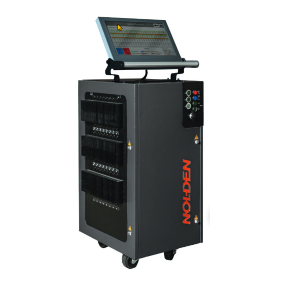
- Page 17 Operations manual NR8000-v3 Tower casing Front view NR 8000 Tower (up to 48 zones) : Fig.: Front NR 8048 Touchscreen Handle to move the system Operation panel with heating switch and direct access keys Lateral door with power electronics Load fuses for every zone...
- Page 18 Operations manual NR8000-v3 Tower casing - STS v 3.0 Front view NR 8000 Tower (up to 80 zones) : Fig.: Front NR 8064 Touchscreen Handle to move the system Operation panel with heating switch and direct access keys Lateral door with power electronics...
- Page 19 Operations manual NR8000-v3 Tower casing Front view NR 8000 Tower (up to 144 zones) : Fig.: Front NR 8144 Touchscreen Operation panel with heating switch and direct access keys Lateral door with power electronics Load fuses for every zone Front door...
-
Page 20: Changing Fuses
Operations manual NR8000-v3 Tower casing - STS v 3.0 4.5 Changing fuses Before exchanging whatever fuse, it is mandatory to disconnect the unit from mains voltage supply and protect against re-connecting! Exchanging the externally accessible load fuses : 1. Remove the fuse holder cap with an appropriate (wide) screw driver 2. - Page 21 Operations manual NR8000-v3 Tower casing Exchanging the internally accessible controller fuse (picture see below) : 1. Remove the casing cover (pay attention to internal earth wiring!) 2. Pull out the fuseholder on the electrical terminal block on C-rail (unit floor) 3.
-
Page 22: Operation
Operations manual NR8000-v3 Tower casing - STS v 3.0 Operation 5.1 Main switch Before wiring the device, make sure that the master switch on the back side is in Herewith, all poles are disconnected from the mains voltage. position OFF „0“. -
Page 23: Operating Elements And Keys
Operations manual NR8000-v3 Tower casing 5.2 Keys and operation elements Control panel NR 8000-v3 Tower up to 80 zones Phase control lights (one for each phase) Standby-switch (second setpoint) Manual boost (temporary setpoint increase) Main switch electronics and touchscreen ON / OFF-switch heating USB-socket The stand-by function can also be activated from an external signal source, e.g. -
Page 24: Safety Loadshedding
Operations manual NR8000-v3 Tower casing - STS v 3.0 5.3 Safety loadshedding : In addition to both alarms A1 and A2, a safety loadshedding function („alarm A0“) is wired to the heating masterrelay of the system. This functions cuts automatically the total heating power of the mould, when a process-high temperature in access of 50°C is measured somewhere in the mould. -
Page 25: Nolden Sts Smart Touch System
The “Arrow” or “Back”-button will lead you to the last visited screen (this can also be the homescreen, if you just were there). On the Homescreen, the 6 main functions of the NOLDEN STS can be chosen : Alarms Real time analysis... -
Page 26: Part „Heating" - View Total Situation
Operations manual NR8000-v3 Tower casing - STS v 3.0 Depending on other options eventually installed, more buttons may appear on the homescreen. Those programs are then described in a separate manual for every option. Hotrunner is the most frequently used screen, all actual values and conditions are shown here. - Page 27 Operations manual NR8000-v3 Tower casing In the upper part of the screen, functions to operate all heating zones together are shown : Quicklink to mould memory Display actual mould name ON / OFF all (see chapter 6.6) active zones Temp + / -...
- Page 28 Operations manual NR8000-v3 Tower casing - STS v 3.0 - Boost : For all zones, the boost-setpointaddition is activated for a limited period of time. This Boost holding time is hold after the boost-setpoint temperature is reached, then, every zone goes back to the last operation setpoint.
- Page 29 Operations manual NR8000-v3 Tower casing Examples for the display of one single zone (cont.) : Zone number (consecutive) Group of zones, example shown : Manifold (see chapter 6.3.4) Name of the zone, defined by the operator Operational state, example shown: Coupled to other zone...
- Page 30 Operations manual NR8000-v3 Tower casing - STS v 3.0 selecting or de-selecting of certain zones, Finally, you may select „All zones“ by pressing the associated button, also this choice can be modified afterwards. When all required zones are selected, you can increase or decrease the setpoint of each individual zone by the indicated amount.
-
Page 31: Zones - View In Groups
Operations manual NR8000-v3 Tower casing 6.2.1 Zones - view in groups Zonen 1 - 8 150°C 150°C 150°C 150°C 150°C 150°C 150°C 150°C 6,7 A 0,8 A 1,2 A 1,2 A 0,8 A 6,7 A 6,7 A 1,2 A With the arrow keys, you can roll through all groups of zones. In this screen, all zones... -
Page 32: Zones - Details
Operations manual NR8000-v3 Tower casing 6.2.2 Zones - detail view 230°C 230°C 1,6 A Arrow keys next / previous zone Display name and group of the actual zone Display alarms ON-/OFF-switch heating actual zone Display and modification of parameters Entering zones configuration... - Page 33 Operations manual NR8000-v3 Tower casing Ad 1.) and 2.) Display name and group of the actual zone, arrow keys Here, the name of the selected zone is displayed, if a name is assigned. If no name is assigned, just the number of that zone is shown. Beside the name of the zone, the affiliation of a group of zones is displayed.
- Page 34 Operations manual NR8000-v3 Tower casing - STS v 3.0 Remark 2 : To ease the entering of names, a „quick choice“ menu with frequently used names (tip, manifold etc.) can be used. After having chosen the desired name, this name appears then in the entering field.
- Page 35 Operations manual NR8000-v3 Tower casing If a higher and a lower alarm limit value are defined, the entering menu looks as be- low : 10°C 20°C If only one (or none) of both alarm limit values is activated, only the respective entry field can be operated.
- Page 36 Operations manual NR8000-v3 Tower casing - STS v 3.0 Ad 5.) Display and modification of parameters: Actual temperature, background colour indicates the operational state (see chapter 6.2). Actual setpoint temperature, can be 230°C 230°C altered when field is preseed Actual powersetting of the controller...
- Page 37 This button is normally blocked for the user, the key lock is indicated by a light colou- ring of the key. This is also true for key locks in all parts of the NOLDEN STS. Locked keys guide you directly into the user management section (see chapter 9.1), where you may adjust your user right level, if appropriate.
- Page 38 Operations manual NR8000-v3 Tower casing - STS v 3.0 To remember the zone, from which the values are copied, it is marked light (see previous page, zone 1). Zones switched off are marked in grey (see below, zones 9 –...
- Page 39 Operations manual NR8000-v3 Tower casing Example shown : Actual temperature 250°C Setpoint value 250°C Lower alarm limit 200°C Higher alarm limit 300°C If the actual temperature is outside these treshold limits, temperature alarm is then activated for this zone. In all screens, this zone is then marked in red.
-
Page 40: Settings - Zones Configuration
Operations manual NR8000-v3 Tower casing - STS v 3.0 6.2.3 Zones conf iguration In the zones configuration, mould and/or production order specific parameters of the controller system can be set, that typically do not have to be changed during current operation. All parameters of all zones can be stored in the mould memory and easily reloaded during the next use of that same mould. - Page 41 Operations manual NR8000-v3 Tower casing Dialogue menu „Setpoints“ : When selecting this function, the following dialogue menu opens : - Setpoint 1 - Operation : This parameter is the setpoint for normal operation of every zone, it is the only one of all parameters shown here that can also be changed by a normal operator with the user rights „Operator“...
- Page 42 Operations manual NR8000-v3 Tower casing - STS v 3.0 Example: Setpoint 1 = 200°C, Boostaddition = 10°C, gives a Boost-setpoint of 210°C The boost-setpoint is activated by choosing the temporary boost via the screen or with the dedicated „Boost“-key on the front panel. Upon reaching of the boost-set- point, temperature is hold for a programmable time, then automatically brought to the normal setpoint 1.
- Page 43 Operations manual NR8000-v3 Tower casing - Power setting limitation : Value in % Limitation of the power setting is only required for a too high heating power instal- led in this zone (e.g. heater with the desired dimensions only available with higher power).
- Page 44 Operations manual NR8000-v3 Tower casing - STS v 3.0 Dialogue menu „Softstart“ : 230°C Softstart-setpoint : Value in °C 5 min Softstart-duration : Value in min Softstart-powersetting : Value in % 50 % Softstart vorgewählt: Softstart can be preset for every zone individually. The entered softstart parame- ters are only active for the actual zone, if the sliding switch „Softstart preset“...
- Page 45 Operations manual NR8000-v3 Tower casing Dialogue menu „Alarm-configuration“ : After choosing alarm configuration, a selection menu appears first to determine which alarm shall be configurated : 50°C 0,5 A 100 % - Load shedding / Limit alarm : When pressing the button „Limit value alarm“, the numpad opens (see also chapter 6.2.2), where you can enter the desired limit alarm value.
- Page 46 Operations manual NR8000-v3 Tower casing - STS v 3.0 - Temperature alarm : After having chosen „Temperature alarm“, the following window opens : 20°C 10°C The upper and lower alarm threshold value can be activated and set separately. After having activated one or both alarms, the associated alarm scheme is shown on the right side.
- Page 47 Operations manual NR8000-v3 Tower casing All temperature alarms of all zones are operating the common alarm A1, which is wired to a floating contact on the alarm connector on the back of the device, see chapter 4.4 . Is the temperature alarm configurated as a range alarm or low temperature alarm, the common alarm A1 can be used for production release of an injection press.
- Page 48 Operations manual NR8000-v3 Tower casing - STS v 3.0 Leakage alarm : To monitor the actual powersetting of all active zones, a maximum alarm power- setting (in%) can be defined. If this alarm threshold value is reached in one or more zone(s), leakage alarm is activated.
- Page 49 Operations manual NR8000-v3 Tower casing The leakage alarm does not influence the actual control behaviour, that means the alarm threshold value does not limit actual heating power-setting. If this shall be done, a powersetting limitation can be set, see chapter „zones configuration - set- points“.
- Page 50 Operations manual NR8000-v3 Tower casing - STS v 3.0 Dialogue menu „Manual powersetting“ : Touching the button „Manual powersetting“ opens the following menu : 100 % To switch over to manual powersetting, move the sliding switch to „ON“. If the displayed powersetting is not suitable, press the display field, the known numpad then opens (see also chapter 6.2.2), where you can enter the desired powersetting...
- Page 51 Operations manual NR8000-v3 Tower casing Dialogue menu „Synchronized heating“ : With the function „Synchronized heating“, all zones are heated up together, this means that all zones reach the same temperature at approximately the same time. This avoids that quick zones (e.g. the hot tips) reach their setpoint temperature much earlier than slower ones (e.g.
- Page 52 Operations manual NR8000-v3 Tower casing - STS v 3.0 The name, that all zones shall have in common, must be given to the first zone in the row, which then will be number 1. Press then the Autonaming“ button, which opens the copying field known from other copy procedures in the zone detail view.
- Page 53 Operations manual NR8000-v3 Tower casing Dialogue menu „Grouping of zones“ : Each zone can be assigned to one of 7 groups : „Tip“ = Nozzle „Man“ = Manifold „A“ = Group A „B“ = Group B „C“ = Group C „D“...
- Page 54 Operations manual NR8000-v3 Tower casing - STS v 3.0 When modifying this threshold value, press afterwards the button „Restart auto- grou- ping“, this performs the process again according to the new threshold value. The automatic group assignment can be changed at any time by the operator. Also, you can de-activate manually the assignment to a group.
- Page 55 Operations manual NR8000-v3 Tower casing Up to 5 groups of zones can be heated up one by one. Every group is heated until a predefined temperature is reached, then waits for a given delay time (if set), then the next group starts its heating in the same manner.
-
Page 56: Part „Mould Diagnosis
Operations manual NR8000-v3 Tower casing - STS v 3.0 6.3 Mould diagnosis The mould diagnosis function performs a wiring check of all connected thermo- couples and heating elements on good allocation to the same zone. Check of good functioning of every thermocouple and heater itself is done continuously during cur- rent operation and does not require a mould diagnosis. - Page 57 Operations manual NR8000-v3 Tower casing Attention : During the mould diagnosis, a weak heating pulse is subsequently given on every zone, then the temperature increase on that zone is checked. This is done at low temperature (max. 120°C), so that normally, no cooling device is required (only for very delicate moulds).
- Page 58 Operations manual NR8000-v3 Tower casing - STS v 3.0 For more information about the analysis result in one particular zone, press the field of this zone, the following window then shows up : This can also be done during the current analysis to follow its progress. The pre-set diagnosis time is count-up, as soon as the sensor is detected, diagnosis for this zone stops and the next zone is taken.
- Page 59 Operations manual NR8000-v3 Tower casing The „enhanced view“ gives immediately the result for every zone with a symbol, but depending on the total number of zones, you must use the roll bars on the right side to see all zones. Also in the enhanced view, you can access the detail result by pres- sing the associated zone field (see previous page).
-
Page 60: Part „Analysis
Operations manual NR8000-v3 Tower casing - STS v 3.0 The memory device is connected via the USB-port on the back side of the device. Attention: Given the USB interface definition, any USB-port is hasardous as well from the hardware- (EMV) as from the software standpoint. Please consider this when defining rules of access to the unit. - Page 61 Operations manual NR8000-v3 Tower casing If the control behaviour of a given zone shall be analyzed in detail, pressing the „zone“ button opens a curve showing that zone: Analysis Zone: 1 With the arrow keys (left and right of the zone number), you can scroll through all zones.
-
Page 62: Part „Mould Memory
Operations manual NR8000-v3 Tower casing - STS v 3.0 Mould memory With the mould memory, all parameters of all zones can be stored to be reloaded if this mould is re-used for the next time in production. The mould memory is used for all functions or options present in the actual device, that means, all settings of all functions are stored here. - Page 63 Operations manual NR8000-v3 Tower casing Attention : When a mould is loaded from the memory (also the default settings), all actual parameters are overwritten and so, lost. If you have found an actual set of para- meters by trials, save them first as described below as a different mould (new name).
- Page 64 Operations manual NR8000-v3 Tower casing - STS v 3.0 Loading a set of parameters : 1. Choose the desired mould (the name is then marked in GREEN Werkseinstellung - Reset Werkseinstellung - Reset NR8000 - Backup Sealing cap 123450 2. Press „Loading mould“...
- Page 65 Operations manual NR8000-v3 Tower casing Deleting a set of parameters : 1. Choose the desired mould (the name is then marked in GREEN 2. Press „Deleting mould“ 3. Acknowledge with „OK“ Delete Sealing Cap 123450 ? Attention : Deleting a mould from the memory removes all associated parameters and set- tings irrevocably.
-
Page 66: Part „Alarms
Operations manual NR8000-v3 Tower casing - STS v 3.0 Alarms With the program „Alarms“, all actual and previous alarms can be checked. After having choosen the program, a list of all actual alarms appears first. If an alarm dissappears (problem solved), this alarm is also automatically deleted from the list. - Page 67 Operations manual NR8000-v3 Tower casing History NOLDEN Regelsysteme GmbH...
-
Page 68: Part „Settings
Settings This button on the Homescreen leads you to the functions „Settings“ of the NOLDEN STS. The extent of the available functions depends on the rights of the actual user (see next page). Functions which are not allowed with the actual rights are covered dark (see example below, „System“) - Page 69 Operations manual NR8000-v3 Tower casing Bediener The active user at this very moment is indicated by a green colouring of the button (see red arrow). After the choice of the desired type of user, a PIN-code must be entered, which can be specificly defined by an administrator.
- Page 70 Operations manual NR8000-v3 Tower casing - STS v 3.0 With user rights as „Administrator“ , an enhanced view is shown : Administrator Here, two other functions are accessible, that are not displayed to other users : - Modification of password...
-
Page 71: Settings - Language
Operations manual NR8000-v3 Tower casing - Change user rights at start-up : When selecting this function, the following menu opens, where the user right level when starting-up the system can by modified (Factory default = „Operator“) 9.2 Settings - Language Deutsch The choice of the actual language is confirmed by a green colouring of the key. -
Page 72: Settings - System
Operations manual NR8000-v3 Tower casing - STS v 3.0 9.3 Settings - System Settings in this menu are valid for one part on the whole system, that means all present options and functions together. The other part concerns every single option in the system with parameters that should not be accessible for normal users. - Page 73 15m depending on local conditions. 2. Selecting HTML-page : The easiest way to do so is to scan the QR-code shown on the NOLDEN screen and press „Activating link“, „Connecting“ or so on your device. With newer devices, a QR- code scanner is integrated into the camera.
-
Page 74: Date/Time Setting
Operations manual NR8000-v3 Tower casing - STS v 3.0 - Date-/ Time setting : The date-/time setting is an operating system function of the industrial computer used in this unit, all time relevant program functions use it. This is of particular significance for functions with date / time stamp such as e.g. - Page 75 Operations manual NR8000-v3 Tower casing - Software-Update : With this function, the complete program software of the controller can be updated. This function is only accessible for users with the user right level „Admini- strator“. The update is definitive, this operation cannot be withdrawn without additional actions.
- Page 76 Operations manual NR8000-v3 Tower casing - STS v 3.0 The „OK“ key is only enabled, if a functioning USB memory device is recognized on the USB data port on the back side. Otherwise, the key is shown in light grey and cannot be operated.
- Page 77 82.3, 82.4 (cooling systems, robots) are not suitable. If the NOLDEN unit is equipped with additional interface types, eg. the classical TTY- interface (Arburg / HB-Therm), only one of both can be used. As TTY-interface is always active and can‘t be activated or switched off, it is mandatory to switch off...
-
Page 78: Settings Temperature Control
„KNN“ is the abbreviation for „Künstliche Neuronale Netzwerke“ (German) or „Artificial Neural Networks“. Is designates the control algorithm, which is used by the NOLDEN STS, please see also the general explanation on next page. Temperature control of your NOLDEN unit is fully automatic, that means with automatic adaptation to the characteristics of every connected heating zone. - Page 79 Operations manual NR8000-v3 Tower casing For normal control operation, „Automatic“ must be selected. Is this done, the auxiliary control program „Mode 1“, Mode 2“ or „Mode 3“ actually selected by the system is displayed, both by a green colour of the key. If „Automatic“ is disabled and one of the three auxiliary programs is manually activated, no automatic adaptation of the control to the heated zone takes place anymore.
- Page 80 „hidden layers“. This control algorithm is used by the NOLDEN STS instead of the traditional PID control method used up to now by most systems. The most prominent disadvantages of PID control, the so called „overshoot“...
-
Page 81: Settings - Further Options
Operations manual NR8000-v3 Tower casing Thermocouples type „J“ (Fe-CuNi) or „K“ (Ni-CrNi) can be selected. In case of ther- mocouples type „J“, you may also choose between an upper limit of the measuring range of 400 or 800°C. Attention : When changing the type of thermocouple („J“... - Page 82 Operations manual NR8000-v3 Tower casing - STS v 3.0...
-
Page 83: Appendix
Operations manual NR8000-v3 Tower casing 10 Appendix Other pin assignments for 24-pole connector SN 10-24 („HASCO“) SN 03-24 SN 04-24 SN 05-24 (Thermocouple / heater separated) Heater NOLDEN Regelsysteme GmbH... - Page 84 Operations manual NR8000-v3 Tower casing - STS v 3.0 Appendix (cont.) Other pin assignments for 16-pole connector SN 10-16 („HASCO“) SN 04-16 SN21-16 „Euromap 14“ Heater (heavy connector) (narrow connector) Serial interface TTY 20mA (ARBURG or others, OPTION) Ilme CKF03...
-
Page 85: Keyword Index
Operations manual NR8000-v3 Tower casing 11 Key word index Subject : Page : Actual temperature zone..…………………………………………. 28 ff. Alarm configuration...……………………………………………… 46 ff. Alarm connector…………………………………………………… 13 ff. Alarm de-activate (Temperature)………………………………..46 ff. Alarm history……………………………………………………….. 66 Alarm limit values..………………………………………………… 38, 46 ff. - Page 86 Operations manual NR8000-v3 Tower casing - STS v 3.0 Key word index (cont.) Subject : Page : Mains connection.…………………………………………………... 10 - 14 Manual powersetting……………..………………………………… 50 Measuring zone………………………………………….…………. 43 Mould conncetion cable..…………………………………………. 12 - 14 Mould data - loading.………………………………………………. 64 Mould data - deletin.………………………………………………. 65 Mould data - changing.…………………………………………….
- Page 87 Operations manual NR8000-v3 Tower casing - STS v 3.0 Key word index (cont.) Subject : Page : Update - see software-Update…..………………………………… 75 ff. User right level.…………………………………………………….. 68 User right level at system start...…………………………………. 70 USB-export………………………………………………………….. 59, 65 USB-connector……………………………………………………… 14 ff.
-
Page 88: Declaration Of Conformity
Operations manual NR8000-v3 Tower casing - STS v 3.0 DECLARATION OF CONFORMITY This declaration is valid for the following products : Model designation : Multizone-Temperature controller Type : NR8016-v3 Tower up to NR8144-v3 Tower Hereby is confirmed, that these products meet in their design and...
Need help?
Do you have a question about the NR8000-v3 Tower and is the answer not in the manual?
Questions and answers