
Summary of Contents for Monitrol Varifan ECS-5C
- Page 1 MANUAL ECS-5C Installation / User’s Guide ATTENTION ELECTRICIAN SEE WIRING DETAILS ON PAGES A-3 TO A-6 AND ADDITIONAL INFORMATION IN SECTION B www.monitrol.com...
-
Page 2: Warnings And Precautions
ECS-5C, including the alarm system and backup devices, after installation, after changes to the installation and every month after that. Fuse verification and replacement, as well as the proper setting of control values shall be the responsibility of the owner of this equipment. Section A-2 ECS-5C www.monitrol.com... - Page 3 ECS-5C WIRING DIAGRAM WIRING DIAGRAM ECS-5C SECTION A ECS-5C Section A-3 www.monitrol.com...
-
Page 4: Wiring Diagram
ECS-5C WIRING DIAGRAM Wiring Diagram GREEN RELATIVE HUMIDITY BLACK PROBE RH-3 MGCB WHITE RED CONNECTOR 8VAC INT 4 / EXT INSIDE 4 / OUTSIDE INT 3 INSIDE PROBE 3 INT 2 INSIDE PROBE INT 1 INSIDE PROBE Section A-4 ECS-5C www.monitrol.com... - Page 5 ECS-5C WIRING DIAGRAM DIP-1C INLET POSITIONER MGCB MGCB MODULE 8VAC INT 4 / EXT INSIDE 4 / OUTSIDE INT 3 INSIDE PROBE 3 INT 2 INSIDE PROBE INT 1 INSIDE PROBE ECS-5C Section A-5 www.monitrol.com...
-
Page 6: Electrician's Notes
ENDS. NEVER CONNECT BOTH ENDS OF THE SHIELD TO GROUND PLATE . THE USE OF A SHIELD FOR ALL PROBES IS MANDATORY. REFER TO THE DIP-1C MODULE USER’S MANUAL FOR ADDITIONAL DETAILS ON DIP-1C MODULE AND INLET WIRING. Section A-6 ECS-5C www.monitrol.com... -
Page 7: Section B
ECS-5C INSTALLATION INSTALLATION ECS-5C SECTION B ECS-5C Section B-7 www.monitrol.com... -
Page 8: Unpacking
Shielded two-wire twisted pair cable, AWG #22 (used for communication) see electrician note for capacitance selection. 4 screws (to hang the unit onto the wall). Screwdrivers. Soldering iron kit or approved sealed connectors. Drill and hole saw kit. Section B-8 ECS-5C www.monitrol.com... -
Page 9: General Installation Guidelines
All cable connections must be soldered or done with approved sealed connectors. Probe cables must be 500’ (150m) or less. Communication cables must be 820’ (250m) or less. It is prohibited to use overhead cables outside the building. ECS-5C Section B-9 www.monitrol.com... -
Page 10: Electrical Power
The bracket slots also serve to adjust the position of the controller. Once you have adjusted the controller position, tighten the four mounting screws. FIGURE NO. 1 Mounting Position and Devices Section B-10 ECS-5C www.monitrol.com... -
Page 11: Connection Procedure
It should also be protected from physical damage. FIGURE NO. 2 Typical Temperature Probe Wiring PROBE SHIELD FIGURE NO. 3 Typical Relative Humidity Probe Wiring MODULES LINE 230V ECS-5C Section B-11 www.monitrol.com... -
Page 12: Typical Power Backup Wiring
FIGURE NO. 4 Typical Power Backup Wiring DISTRIBUTION DISTRIBUTION PANEL PANEL LINE LINE 230 VAC 230 VAC source 2 source 1 NO 2 COM 2 NC 2 COM 1 NC 1 NO 1 8 PIN RELAY DPDT (OMRON model MK2EP-UA-AC120) Section B-12 ECS-5C www.monitrol.com... -
Page 13: Typical Thermostat Backup Wiring
3 to 5 degrees above the fan’s relative set point or 3 to 5 degrees under the heater relative set point. FIGURE NO. 5 Typical Thermostat Backup Wiring on Relay RELAY T15WD L2(N) ECS-5C Section B-13 www.monitrol.com... -
Page 14: Figure No. 6 Typical Thermostat Backup Wiring On Variable Stage
ECS-5C INSTALLATION FIGURE NO. 6 Typical Thermostat Backup Wiring on Variable Stage ECS-5C X1300 VAR 1 230 V (ECS-5C) 120V (ECS-5C/120) T15WD L2 (ECS-5C) N (ECS-5C/120) Section B-14 ECS-5C www.monitrol.com... -
Page 15: Typical Alarm Connection Wiring
/or auto-dialer. The relay will activate 6-8 seconds after an alarm is triggered. FIGURE NO. 7 Typical Alarm Connection Wiring TEMP. PROBES MODULES ALARM 30V/1A ALARM SYSTEM / AUTO DIALER ECS-5C Section B-15 www.monitrol.com... -
Page 16: Powering Up Procedure
Verify all Connections Seal all cable entry holes. Hermetically Close the ECS-5C Close the front panel. Put the power on Secure the front panel with a lock Section B-16 ECS-5C www.monitrol.com... -
Page 17: Downloading The Configuration
(MMX) and place it in the bottom part of the enclosure or in another safe location. Once the MMX Chip is removed, the ECS-5C starts up and executes the configuration. Note: During this procedure, some components are live and can be dangerous if touched. ECS-5C Section B-17 www.monitrol.com... -
Page 18: Uploading The Configuration
(MMX) and place it in the bottom part of the enclosure or in another safe location. Once the MMX Chip is removed, the ECS-5C will continue to execute the configuration. WARNING: During this procedure, some components are live and can be dangerous if touched. Section B-18 ECS-5C www.monitrol.com... -
Page 19: Ecs-5C Compatible Probes
DIP-1C (Digital inlet positioner) Computer interface NET-IN2 Communication Module (Module inserted into the controller to communicate with the computer interface) RF-IN Communication Module (Module inserted into the controller for a wireless communication with the computer interface) ECS-5C Section B-19 www.monitrol.com... -
Page 20: Specifications
Minimum load 300mA @ 230VCA (ECS-5C) 150mA @ 120VAC (ECS-5C/120) PLS OUTPUTS Recommended wires 2 conductors, twisted pair (8 twist /ft), AWG #22 Maximum wire length (350pF/m cable) 160ft (50m) Maximum wire length (89pF/m cable) 650ft (200m) Section B-20 ECS-5C www.monitrol.com... - Page 21 1 foot (30 cm) apart. If low-voltage and high-voltage conduits must be crossed, the crossing must be at a 90-degree angle. All wiring must be made by a certified electrician and conform to local electrical regulations. ECS-5C Section B-21 www.monitrol.com...
-
Page 22: Troubleshooting
ECS-5C is not powered. Make sure the control is Flat cable between the powered. main and top boards of the Make sure the fuse is ECS-5C is disconnected. correct. Make sure the flat cable is connected. Section B-22 ECS-5C www.monitrol.com... - Page 23 ECS-5C USER’S GUIDE USER’S GUIDE ECS-5C SECTION C ECS-5C Section C-23 www.monitrol.com...
-
Page 24: Control Description
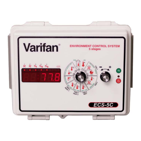
ECS-5C USER’S GUIDE Control Description Varifan ® ENVIRONMENT CONTROL SYSTEM 5 stages MIN SPEED 73.3 TIMER 11 12 1 MIN SPEED ECS-5C Section C-24 ECS-5C www.monitrol.com... - Page 25 This button is used to access to secondary function of a parameter group (appears in green around the parameter dial). 6. SET/CLR Button This button is used to acknowledge a function, set a value (clock, curves) or to clear values (min/max). ECS-5C Section C-25 www.monitrol.com...
-
Page 26: Input/Output Table
Configuration Versions Version Date Min. Proc Modification Version. 11/27/2008 New. 03/30/2010 Update for official release. 05/05/2011 Add wireless communication support. Add DIP-1C support. 10/25/2012 Add Load Delay. 07/08/2014 Add maximum speed on variable stages 1 and 2. Section C-26 ECS-5C www.monitrol.com... -
Page 27: Ventilation System Overview
An alarm check will be made to check for high/low temperature and defective probes. The outside temperature may increase the high alarm threshold. The alarm will also activate if the difference between any two inside probes is too great. ECS-5C Section C-27 www.monitrol.com... -
Page 28: Normal Mode Settings
Then select the point to adjust using the F2 button and adjust it with the adjustment knob. See the Additional information on parameters section for more information on the growth curve. This parameter is adjusted in 1% increments from 12% to 100%. Section C-28 ECS-5C www.monitrol.com... -
Page 29: Variable Fan 1 (Pos 3)
This parameter is used to establish the minimum speed of variable stage 2. Variable stage 2 will be activated at this speed when Average Temperature is equal to the Main Set Point+ Relative Temperature Variable 2. This parameter is adjusted in 1% increments from 12% to 100%. ECS-5C Section C-29 www.monitrol.com... -
Page 30: Fan 3 / Mist (Pos 6)
2 will activate when the average temperature of the probes selected in Heater 2 Probe {1-4} is equal to or below Main Set Point + Relative Temperature Fan 4 / Heater 2. This parameter is adjusted in 0.1° increments from -20.0°F to 20.0°F (-11.1°C to 11.1°C). Section C-30 ECS-5C www.monitrol.com... -
Page 31: Fan 5 / Heater 1 (Pos 8)
ECS-5C was powered up or since this parameter was last cleared. To reset this value to 0, press the SET/CLR button. The Heater 1 Record is displayed to the nearest minute from 0 to 32760 minutes. ECS-5C Section C-31 www.monitrol.com... -
Page 32: Clock / Growth Day (Pos 9)
When Average Temperature is below the Main Set Point + Relative Temperature Low Alarm, a low temperature alarm condition will occur. This parameter is adjusted in 0.1° increments from -40.0°F to -0.5°F (-22.2°C to -0.3°C). Section C-32 ECS-5C www.monitrol.com... -
Page 33: High Temperature Record And Alarm (Pos 11)
Temperature since the ECS-5C was powered up or since this parameter was last cleared. To reset this value to the actual Average Temperature, press the SET/CLR button. The High Average Temperature Record is displayed to the nearest 0.1° from -58.0°F to 140.0°F (-50.0°C to 60.0°C). ECS-5C Section C-33 www.monitrol.com... -
Page 34: Probes (Pos 12)
DIPSW3 is set to the ON position (see DIP Switches and Slide Switches Table page 45). The Probe 3 temperature is displayed to the nearest 0.1° from -58.0°F to 140.0°F (-50.0°C to 60.0°C). Section C-34 ECS-5C www.monitrol.com... -
Page 35: System Mode Settings
See the Additional information on parameters section for more information on the growth curve. If this parameter is set to OFF, the Minimum Speed Variable 1 will not be affected by its growth curve. ECS-5C Section C-35 www.monitrol.com... -
Page 36: (Pos 2)
COOL , output 5 will activate when the Average Temperature is high. If this parameter is set to HEAT , output 5 will activate when the average temperature of the probes selected in Heater 1 Probe {1-4} is low. Section C-36 ECS-5C www.monitrol.com... -
Page 37: (Pos 4)
1 will follow. This parameter will appear only if Logic Out 5 is set to HEAT , DIPSW4 is set to the ON position and DIPSW5 is set to the OFF position (see DIP Switches and Slide Switches Table page 45). ECS-5C Section C-37 www.monitrol.com... -
Page 38: (Pos 5)
Point + Relative Temperature Fan 3 / Mist, fan 3 / mist will be activated for a percentage (Fan 3 / Mist Cycle Time) of this period. This parameter is adjusted in 1% increments from 0% to 100%. Section C-38 ECS-5C www.monitrol.com... -
Page 39: (Pos 8)
Average Temperature is above Outside Probe + Relative Outside Temperature Alarm. Setting this parameter to OFF will deactivate the outside temperature’s influence on the high alarm threshold. This parameter is adjusted in 0.1° increments from 0.5°F to 40.0°F, OFF (0.3°C to 22.2°C, OFF). ECS-5C Section C-39 www.monitrol.com... -
Page 40: (Pos 9)
This parameter is used to select the identification number that will be used when communicating with the remote access software. This parameter may be adjusted to any value from 1 to 250. Tech Param Display TPDIS This parameter is reserved for the manufacturer’s technical support personnel. Section C-40 ECS-5C www.monitrol.com... -
Page 41: (Pos 11)
This parameter displays the version of the processor actually used. (POS 12) System Parameters SYSTM This parameter indicates that the ECS-5C is in system parameter mode. Communication Filter FILTR This parameter is reserved for the manufacturer’s technical support personnel. ECS-5C Section C-41 www.monitrol.com... -
Page 42: Parameter Table
Heater 2 (-11.1 to 11.1°C) FAN 4/HEATER 2 [F2] – – Differential Fan 4 / DIFF 2.0°F (1.1°C) 0.5 to 20.0°F (0.3 to 11.1°C) Heater 2 [F2] – – Heater 2 Record — 0 to 32760 min Section C-42 ECS-5C www.monitrol.com... - Page 43 TEMPERATURE RECORD and [F2] – – Relative 12.0°F (6.7°C) 0.5 to 40.0°F (0.3 to 22.2°C) ALARM Temperature High Alarm 100.0°F -40.0 to 119.9°F, OFF [F2] – – Critical High Alarm CRIT (37.8°C) (-40.0 to 48.8°C, OFF) ECS-5C Section C-43 www.monitrol.com...
-
Page 44: System Mode Settings (Accessible When Sw2 Is Set To On)
– Configuration Version — — CONF (POS 11) [F2] – – Processor Version — — PROC – System Parameters — — SYSTM: (POS 12) [F2] – – Communication FILTR: 300 sec 0 to 300 sec Filter Section C-44 ECS-5C www.monitrol.com... -
Page 45: Dip Switches And Slide Switches Table
ON = Outside / OFF = Inside (DIPSW6) – Humidity Probe* ON/OFF (DIPSW7) – DIP-1C* ON/OFF (DIPSW8) – Future Use — — If DIP SWITCHES 6 and 7 are both ON, the controller will use the DIP-1C logic. ECS-5C Section C-45 www.monitrol.com... -
Page 46: Motor Curve
5KCP39… 230 V. 14” Emerson K55HXJ… 230 V. 14” Oversized motors Flex FM0024 230 V. 12” Flex FM0026 230 V. 20” Multifan 4E30 230 V. 12” Multifan 2E35 230 V. 14” Multifan 4E25 230 V. 10” Section C-46 ECS-5C www.monitrol.com... -
Page 47: Additional Information On Parameters
Select the ramping parameter (ex: Main Set Point, Minimum speed, etc.). Make sure the Growth day is set to OFF. Press the SET/CLR button. At this moment, the first day of the growth curve will be displayed. ECS-5C Section C-47 www.monitrol.com... - Page 48 1, 8, 20 and 60 and the value points are 80°F, 79°F, 75°F and 70°F. 10. Once the last value point is entered, press the SET/CLR button. You should now be back to a point where the LED display is flashing a temperature value. Section C-48 ECS-5C www.monitrol.com...
- Page 49 This characteristic may be useful to users unwilling to use all 4 “preset” ramping points. The following illustration shows how users can stop the curve without entering the last point. ECS-5C Section C-49 www.monitrol.com...
-
Page 50: Section D
ECS-5C INDEX / WARRANTY INDEX / WARRANTY ECS-5C SECTION D Section D-50 ECS-5C www.monitrol.com... -
Page 51: Table Of Contents
FIGURE NO. 4 Typical Power Backup Wiring ........... 12 FIGURE NO. 5 Typical Thermostat Backup Wiring on Relay ......13 FIGURE NO. 6 Typical Thermostat Backup Wiring on Variable Stage ....14 FIGURE NO. 7 Typical Alarm Connection Wiring ..........15 ECS-5C Section D-51 www.monitrol.com... -
Page 52: Table Of Contents
DIP Switches and Slide Switches Table ............. 45 Motor Curve ......................46 Additional information on parameters ..............47 Time of Day (time clock) ..................... 47 Growth Day......................... 47 Ramping ........................47 TABLE OF CONTENTS Section D Limited Warranty ....................53 Section D-52 ECS-5C www.monitrol.com... -
Page 53: Limited Warranty
ECS-5C Section D-53 www.monitrol.com... - Page 54 ECS-5C_EN VER: 1.4 July 11, 2014 www.monitrol.com...
Need help?
Do you have a question about the Varifan ECS-5C and is the answer not in the manual?
Questions and answers