Table of Contents
Advertisement
Quick Links
Advertisement
Table of Contents
Troubleshooting

Summary of Contents for Hammar Control Panel 2
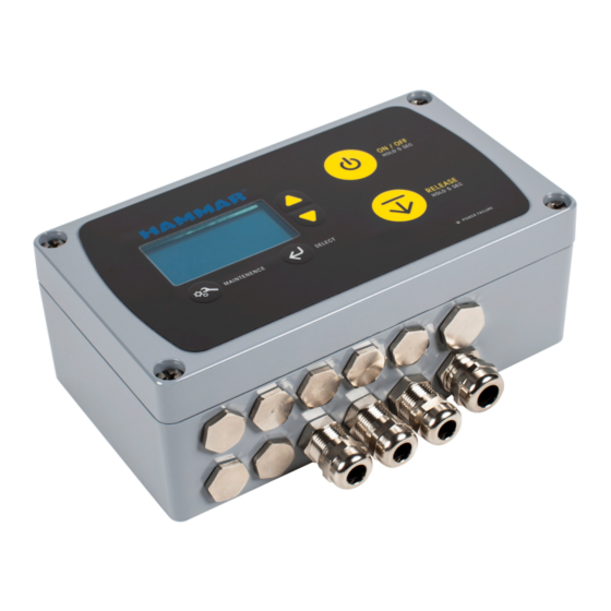
- Page 1 TECHNICAL PRODUCT INFORMATION HM-0710 CONTROL PANEL 2...
-
Page 2: Table Of Contents
Connection cable screens to EMC cable glands ............EMC Cable Glands ........................... INSTALLATION OF CABLE GLANDS ......................INSTALLATION OF GROUND CONNECTION DEVICE ................Inside Control Panel 2 ........................Power Supply ............................ External alarm ..........................TESTING AND VERIFYING THE INSTALLATION .................. -
Page 3: Product Information
The CP2 may be used to open hatches or close fire doors. The HM-0710 has a rechargeable back-up battery (HM-0725) in case of power failure on the ships 24V DC emergency power supply. INPUT SENSORS Input Sensors are optional input connecting to your Control Unit to increased functionality. These relays inform the Control Panel 2 when they detect abnormalities or when a switch has been turned on. Depending on the urgency the Control Panel 2 may proceed with a launch or generate an alarm. Examples of Input Sensors are; • Extra release push buttons located at the embarkation station •... -
Page 4: Release Units
The performance of the system is defined by the customized configuration of the Control Panel 2. The programming allows the system to meet specific requirements for each installation. The configuration of the Control Panel 2 is individually programmed for every vessel and position onboard. The configuration parameters are saved at Hammar and it is possible to quickly deliver a preconfigured replacement panel if needed. Customization Parameters: • Enable activation of LSA in the Control Panel or in any connected Control Panel in a network. -
Page 5: Technical Specifications
GROUND CONNECTION DEVICE 2 x 2 x 0,75mm2, diameter 10mm The device is designed to ensure a good permanent electrical Cable from Control Panel to connector box – HM-0440 connection between the ERRS Control Panel 2 system and to the ships 1 x 2 x0,75mm2, diameter 8mm ground. Each Control Panel 2 must be connected to ships ground. General specification: Marine approved, screened. If the cable is sour-... -
Page 6: Installation Manual
INSTALLATION MANUAL PLACEMENT Control Panel 2 The CP2 shall be placed in a protected position with respect to environment, mechanical damage, and unintended activation from unauthorized persons. For outside placement use a protective enclosure, seal of the enclosure with an easy-to-break seal. The front and back part of the CP2 must be mounted together, for achieving correct environmental protection. Separating the parts in the installation will void guarantees. -
Page 7: Installation Of Cables
CABLE FOR COMMUNICATION BETWEEN CONTROL PANELS: Maximum length 1000 meter. • For cable with a length of maximum 500 meter use 2x2x0.5 mm2 twisted pair, screened cable. • For cable with a length of 500 to 1000 meter use 2x2x0.75 mm2 twisted pair, screened cable. Connection cable screens to EMC cable glands NOTE: All cable screens shall be connected to ships ground and in one end of the cable only. The CP2 is delivered with EMC cable glands for the connection of the screen to the CP2 enclosure. Only use the original type of cable glands. Additional cable glands can be ordered from CM HAMMAR AB. The back part of CP2 shall be connected to ships ground by the Ground Connection Device, see section below. If the screen of the 24 VDC power supply cable is connected to ground at the switchboard it shall then be isolated from the cable gland and enclosure at the CP2 panel. If more two or more CP2 are connected in a network the communication cable between the control panels shall be connected in the EMC cable gland in only one of the control panels. At the other end of the cable the screen shall be isolated from the cable gland and enclosure. EMC Cable Glands The metal EMC cable glands are designed to ensure a good connection between the cable gland and the cable screen. Inside EMC... -
Page 8: Installation Of Cable Glands
INSTALLATION OF CABLE GLANDS Strip the cable and cut the screen to approximately 3 cm. Fold back the screen before inserting the cable into the cable gland. Insert the cable into the cable gland until the screen gets in line with the inner end of the cable gland. This will ensure that the EMC fingers will connect the screen to the cable gland when the cable gland nut is tightened. INSTALLATION OF GROUND CONNECTION DEVICE The screen for the 24VDC power supply cable shall be connected to ground in the Ground Connection Device Mount the Ground Connection Device to a clean metal surface that gives a good connection between the device and ships ground. -
Page 9: Inside Control Panel 2
Inside Control Panel 2 The terminals inside the CP2 enclosure are of spring-loaded type. Inset a small screwdriver in the slot beneath the opening for the wire and bend gently downwards to open the terminal to insert the wire. The maximum wire area for the terminals inside the ERRS CP2 enclosure is 2,5 mm2. Multiple CP2 in Network The communication between ERRS CP2 Control Panels in a network is a RS 485 communication using 3 wires. Power Supply Emergency power shall be connected to all ERRS Control Panels. The voltage level must be within the range 16 - 36 V DC The maximum current consumption for the system is 0,5 A. Internal fuses S1 – 1.0AF 5x20 mm glass tube fuse. See wiring diagram for maximum cable length and area. External alarm The CP2 can be connected to the ships general alarm system. The external alarm function is an isolated normally closed contact (when... -
Page 10: Testing The Systems Outputs
5. At the Connector Box, Remove ERU Emulator and install Jumper Wire in terminals. 6. Proceed to next Connector Box with Jumper Wire and install ERU Emulator in terminals. Confirm ERU Emulator is indicating GREEN flashes. 7. Repeat steps 4 – 8 until all Outputs have been verified correct. 8. Return to the Control Panel 2 o Push ON/OFF button to exit Activation Mode o Push the MAINTENANCE pushbutton. o Toggle to menu item 5 - RESET SYSTEM. o Push SELECT 9. For each Connector Box connect the designated H20 ERU. -
Page 11: Trouble Shooting At Installation
Trouble Shooting at Installation The general guidance for troubleshooting is to start with a reset (MAINTENANCE - 5. RESET SYSTEM). Check if error remains. If Display shows “Check System”, see MAINTENANCE - 2. SYSTEM ERRORS. Proceed to section Trouble Shooting in User Manual. If error remains, work from the CP2 and outwards towards the Connector Box and H20 ERU. • Measure input voltage to 24VDC. • Check connection between front and back part of CP2 Enclosure • Check for cables with poor connections. Confirm Ground Connection Device is connected and screen in cables are touching cable glands, if not there might be some interruption from other devices ERROR SOLUTION After activation, ERU Emulator is flashing GREEN Confirm correct installation of wiring and no damage to cables. • Check correct front part is connected to matchingback part, both parts are marked with a label for position. Reefer to Wiring Diagram. CP2 in network are not communicating • Check ID-switch is in correct position according to Wiring Diagram. • Check the connection of the 3 wires in cables connecting CP2s are in correct ports, refer Wiring Diagram. ERROR CODES FOR CP2 IN NETWORK Test of communication between control panels connected in network has failed to specified panel. “Communic ([ID of panel)” - •... -
Page 12: User Manual
Sensors (Input Sensors). When installed the Control Panel 2 needs minimum attention and service. Every second year you need to replace your ERUs and in between the CP2 OLED display will tell you how and when you need to interact with the system. When an ERU is connected to a Control Unit it is considered an Output from the Control Units perspective. -
Page 13: Keyboard
KEYBOARD ON/OFF button: takes the system between Sleep Mode and Activation Mode. The button must be pressed for 5 sec to turn the system into Activation Mode (a progress bar will go from left to right on the display when the button is pushed). In Activation Mode display will show items possible to release. A push to the ON/OFF button will take system to Monitoring Mode. RELEASE button: in Activation Mode, is used to activate the H20 ERU or relay outputs by pressing and holding the button for 5 sec (a progress bar will go from left to right on the display when the button is pushed). When Activation Mode is off the RELEASE button is without function. Scroll buttons: (arrows to the right of the display) are used to toggle between objects on the display. The scroll buttons are also used in the MAINTENANCE menu. MAINTENANCE: in Monitoring Mode pushing the MAINTENANCE button enters Maintenance Mode. It is also used to exit a sub-menu in the Mode. SELECT: used to select options in menus in Maintenance Mode. POWER FAILURE led indicator. -
Page 14: Quick Guide To Release
QUICK GUIDE TO RELEASE Push and hold the ON/OFF button for 5 sec (a progress bar will go from left to right on the display when the button is pushed) Scroll with yellow arrows (if possible in your configuration) to select the item you want to release. Push and Holding the RELEASE button for 5 sec (a progress bar will go from left to right on the display when the button is pushed). Raft/output released. Repeat until all rafts are released. -
Page 15: System Modes
SYSTEM MODES Monitoring Mode The system is in default in Monitoring Mode. The display is blank if no errors are present. If an error is detected the display will show “Check System”, see Maintenance Mode. Push ON/OFF once to enter Monitoring Mode. Activation Mode Activation Mode is entered by pushing and holding the ON/OFF button for 5 sec (a progress bar will go from left to right on the display when the button is pushed). In Activation Mode Outputs may be activated by pushing and holding the RELEASE button for 5 sec (a progress bar will go from left to right on the display when the button is pushed). The display will show a list of the possible outputs to activate. If the scroll function is in the software configuration for the specific Control Panel the Scroll Buttons may be used to scroll between options to release. To exit Activation Mode, push ON/OFF button once. Maintenance Mode To enter Maintenance Mode, confirm system is in Monitoring Mode and push the MAINTENANCE button. In the Maintenance Mode the system status can be examined. The menu has 7 sub-menus: 1. – System status 2. – System errors... - Page 16 5. Reset system When selected a system reset is carried out for the Control Panel 2. A system reset shall be carried out after any output has been activated and the connected (used) H20 ERU has been replaced with a new unit. N.B! Other connected lifesaving equipment may also need to be returned into operational status before the complete system is returned to operational status. 6. Programming For Hammar use only. Programming is only used when downloading new software into the Control Panel 2. If this option is selected by mistake, just wait for a couple of minutes and a message ”Programming error - Press any key” will appear. Press any key to exit the programming section. 7. Battery test For Hammar use only. The battery test measures the time to discharge the battery to a nearly empty level. Note, the result is not equivalent of the time that the system can run on the back up battery. The system will be able to run on the backup battery for about: twice the measured time in...
-
Page 17: System Check
SYSTEM CHECK The CP2 perform internal checks at short intervals. The functions checked by the System Check are: • Voltage of power supply • Voltage of back-up battery • Internal temperature • Output circuits to H20 ERU units • “Broken cable” on system inputs (optional) • Communication between control panels in connected network • Faults in other control panels in the network • In case of a power failure on the 24VDC power supply a red LED marked “Power failure” will light up on the front of the control panel. The “Check system” message will not come up on the display to save battery power. The alarm relay output will open to indicate failure. PERIODIC CHECKS AND TESTS Once per month (advised). Press MAINTENANCE, to confirm panel wakes up, this check confirms power supply. Press ON/OFF once to go back to Monitoring Mode PERIODIC MAINTENANCE Before performing service or test; Secure Rafts. -
Page 18: Troubleshooting
24VDC in ports: - D1 (+) & E1 (-) - C9 (+) & C10 (-) Panel is not responding to pushes to button • Check for bad connections in ports D1 & E1. • Check for bad connections in C9 & C10. • Check the fuse, check correct resistance. Reposition panel, if still unresponsive, contact CM Hammar for support. If the error can be isolated to certain section of the system: • Check the section for corroded connections and Intermittent error • cables, all the way from CP2 to Connector Box and ERU. • Check for cable breaks and poor connections in rest of system. Red LED “Power Failure” is on See section below Error Code “Supply Voltage”... - Page 19 Error Code “Battery capacity” • If error remains, Replace the Back-up battery • Check the internal temperature in MAINTENANCE - 1. SYSTEM STATUS. • Check the temperature at the location where the CP2 enclosure is mounted. Error Code “Temperature” The operating temperature range for the system is -30 to +65 °C. If outside range, arrange with heating or cooling at the CP2 mounting location. An unused H20 ERU connected to a Control Panel 2 creates a low resistance closed circuit. The System Check is testing this closed circuit, which means that it can detect a released or missing H20 ERU as well as a cable breakdown (open circuit) but not a short-circuit in the cable. The error can be of the following types: • Broken circuit to the ERU. Check the wiring to the ERU and check all terminals Error Code “Output [Output number]” for bad connection and corrosion. Disconnect the ERU and replace the ERU with a jumper wire between the connection terminals. If the error indication goes away, there is a broken circuit in the ERU, replace the ERU.
-
Page 20: Replacement Manual
REPLACEMENT MANUAL REPLACING BATTERY Replacement Part number HM-0725, Rechargeable Battery Pack for Control Panel 2 Switch of the circuit to which the CP2 is connected for power supply. Standing in front of the Control Panel 2, remove the front part by the 4 Ph2-screws in each corner of the panel. Carefully place the front part in a place where in will not be damaged. Replace the battery and dispose the old in an environmentally friendly way. Reattach the front part. Switch on circuit for power supply Check Battery voltage (MAINTENANCE - 1. SYSTEM STATUS) Confirm voltage is increasing to normal operating voltage, 6,8V (+/-0,4V) Replacement completed. REPLACING H20 ERU Refer to specific information for the type of H20 ERU installed. Replacement generally performed by a service technician.
Need help?
Do you have a question about the Control Panel 2 and is the answer not in the manual?
Questions and answers