
Summary of Contents for ICP DAS USA AFAN-02
- Page 1 AFAN-02 AFAN-04 1U Universal Cooling Fan User Manual Version 1.00 AFAN-02/04 User Manual v1.00 ------------------...
- Page 2 Copyright Copyright © 2024 ICP DAS Co., Ltd. All rights are reserved. Trademarks Names are used for identification purposes only and may be registered trademarks of their respective companies. AFAN-02/04 User Manual v1.00 ----------------------...
-
Page 3: Table Of Contents
..............................6 YSTEM PECIFICATIONS 2.2............................7 ODULE PECIFICATIONS 2.3................................8 SSIGNMENTS DIMENSIONS ................................ 9 INSTALLATION ..............................11 FAQ ..................................13 Q01:How to replace the defective fan ? ....................... 13 REVISION HISTORY ............................17 AFAN-02/04 User Manual v1.00 ----------------------... -
Page 4: Introduction
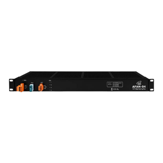
1. Introduction AFAN-02 / AFAN-04 is a 1U general-purpose fan module developed by ICP DAS. It is designed with many advantages for the thermal management of computer room or industrial equipment. The main features are included as below. [1] Fan Modules: AFAN-02 / AFAN04 equips with 2/4 fan modules separately and... -
Page 5: Features
Fig 1-1:AFAN02/04 Application Features Fan Module : AFAN-02/04 equips 2/4 fan modules respectively (hot-swap). Diagnostic Functions : Individual fault LED for each fan. DO Relay alarm output for any fan failure or power loss. Failure of any fan does not affect others. -
Page 6: Specifications
Dimensions (W x L x H) 299 x 144 x 45 mm 480 x 131 x 45 mm Installation Wall-mounted Environment Operating Temperature -10℃ ~ +70℃ Storage Temperature -30℃ ~ +80℃ Humidity 10 to 90% RH, Non-condensing AFAN-02/04 User Manual v1.00 ----------------------... -
Page 7: Fan Module Specifications
MTBF 70K (hours @ 40°C, 65% humidity, 90% CL.) PROTECTION Automatic Restart, Polarity Protection SAFETY Safety E77551 E77551 Note: This hardware specification is only for one fan module. AFAN-04 can support Max. 4 fan module. AFAN-02/04 User Manual v1.00 ----------------------... -
Page 8: Pin Assignments
NC of the relay to the DI module channel (the circuit needs to be wired by users), when the DI channel lights up, it indicates that the fan module is abnormal. Description Relay output: NO. Relay output: COM Relay output: NO. Form C, 6A AFAN-02/04 User Manual v1.00 ----------------------... -
Page 9: Dimensions
3. Dimensions [ AFAN-04 ] (Unit:mm) Top View Front View Left Side View AFAN-02/04 User Manual v1.00 ----------------------... - Page 10 [ AFAN-02 ] (Unit:mm) Top View Front View Left Side View AFAN-02/04 User Manual v1.00 ----------------------...
-
Page 11: Installation
4. Installation [1] Use a screwdriver and M6 screws to install AFAN-02/04 on the cabinet Fig. 4-1 [2] Installation Example. AFAN-02/04 User Manual v1.00 ----------------------... - Page 12 Fig. 4-2 AFAN-02/04 User Manual v1.00 ----------------------...
-
Page 13: Faq
2. Remove the defective fan: [1] Switch off the fan and remove the 4 fan fixing screws (Fig. 5-1-3). [2] Remove the defective fan (Fig. 5-1-4). [3] Unplug the defective fan (Fig. 5-1-5). 圖 5-1-3 AFAN-02/04 User Manual v1.00 ----------------------... - Page 14 3. Replace the normal fan: [1] Remove the 4 metal plate screws and take out the defective fan (Fig. 5-1-6). [2] Install the normal fan to the metal plate and lock the 4 screws (Fig. 5-1-7). AFAN-02/04 User Manual v1.00 ----------------------...
- Page 15 4. Mount the fan to the AFAN: [1] Plug in the fan's power plug (Fig. 5-1-8). [2] Mount the fan to the AFAN and lock the 4 fan fixing screws (Fig. 5-1-9). [3] Replacement is complete. Fig. 5-1-8 AFAN-02/04 User Manual v1.00 ----------------------...
- Page 16 Fig. 5-1-9 AFAN-02/04 User Manual v1.00 ----------------------...
-
Page 17: Revision History
6. Revision History Revision Date Description of Change 1.00 2024/08/29 Document release. AFAN-02/04 User Manual v1.00 ----------------------...
Need help?
Do you have a question about the AFAN-02 and is the answer not in the manual?
Questions and answers