
Subscribe to Our Youtube Channel
Related Manuals for Rohde & Schwarz R&S NRP S Series


Summary of Contents for Rohde & Schwarz R&S NRP S Series
- Page 1 ® R&S NRPxxS(N) Three-Path Power Sensors User Manual (;ÛÀÝ2) 1177507902 Version 22...
- Page 2 This document describes the following three-path diode power sensors with firmware version 03.20 and higher: ● ® R&S NRP8S (1419.0006K02) ● ® R&S NRP8SN (1419.0012K02) ● ® R&S NRP18S (1419.0029K02) ● ® R&S NRP18SN (1419.0035K02) ● ® R&S NRP33S (1419.0064K02) ●...
-
Page 3: Table Of Contents
® Contents R&S NRPxxS(N) Contents 1 Safety and regulatory information............9 Safety instructions......................9 Labels on the product....................10 Warning messages in the documentation..............11 2 Welcome....................12 Documentation overview....................12 2.1.1 Getting started manual....................12 2.1.2 User manuals........................ 12 2.1.3 CD-ROM........................12 2.1.4 Instrument security procedures..................13 2.1.5 Printed safety instructions..................... - Page 4 ® Contents R&S NRPxxS(N) Host interface......................32 Trigger I/O connector....................32 LAN PoE interface.......................32 5 Operating concepts................34 R&S NRP‑Toolkit......................34 5.1.1 Versions and downloads....................34 5.1.2 System requirements....................34 5.1.3 R&S NRP‑Toolkit for Windows..................35 Web user interface...................... 37 Remote control......................38 R&S NRPV........................38 R&S Power Viewer......................
- Page 5 ® Contents R&S NRPxxS(N) 7.2.2 Using the web user interface..................61 7.2.3 Using FTP........................62 7.2.4 Using remote control..................... 63 8 Replacing an R&S NRP‑Zxx with a sensor........64 Important difference....................64 How to proceed......................64 9 Remote control commands..............66 Conventions used in SCPI command descriptions..........66 Notations........................67 Common commands....................68 Preparing for the measurement.................72...
- Page 6 ® Contents R&S NRPxxS(N) 9.8.2 Setting the result format....................126 Querying measurement results................127 9.9.1 Continuous average measurement results..............127 9.9.2 Burst average measurement results................128 9.9.3 Timeslot measurement results..................128 9.9.4 Trace measurement results..................129 9.10 Calibrating, zeroing....................131 9.11 Testing........................133 9.12 Configuring the system....................
- Page 7 ® Contents R&S NRPxxS(N) 10.5 Trace measurement with synchronization to measurement complete....158 11 Remote control basics...............160 11.1 Remote control interfaces and protocols............... 160 11.1.1 USB interface......................160 11.1.2 Ethernet interface......................162 11.2 Status reporting system................... 163 11.2.1 Overview........................164 11.2.2 Device status register....................165 11.2.3 Questionable status register..................
- Page 8 ® Contents R&S NRPxxS(N) User Manual 1177.5079.02 ─ 22...
-
Page 9: Safety And Regulatory Information
® Safety and regulatory information R&S NRPxxS(N) Safety instructions 1 Safety and regulatory information The product documentation helps you use the product safely and efficiently. Follow the instructions provided here and in the following sections. Intended use The sensors are intended for accurate and uncomplicated power measurements in production, R&D and calibration labs as well as for installation and maintenance tasks. -
Page 10: Labels On The Product
® Safety and regulatory information R&S NRPxxS(N) Labels on the product Reconfigure or adjust the product only as described in the product documentation or the specifications document. Any other modifications can affect safety and are not per- mitted. Never open the casing of the product. Only service personnel authorized by Rohde &... -
Page 11: Warning Messages In The Documentation
® Safety and regulatory information R&S NRPxxS(N) Warning messages in the documentation 1.3 Warning messages in the documentation A warning message points out a risk or danger that you need to be aware of. The sig- nal word indicates the severity of the safety hazard and how likely it will occur if you do not follow the safety precautions. -
Page 12: Welcome
® Welcome R&S NRPxxS(N) Documentation overview 2 Welcome This section provides an overview of the user documentation and an introduction to the R&S NRPxxS(N). 2.1 Documentation overview This section provides an overview of the R&S NRPxxS(N) user documentation. Unless specified otherwise, you find the documents at: www.rohde-schwarz.com/manual/nrp_s_sn Further documents are available at: www.rohde-schwarz.com/product/nrp_s_sn... -
Page 13: Instrument Security Procedures
® Welcome R&S NRPxxS(N) Key features 2.1.4 Instrument security procedures Deals with security issues when working with the R&S NRPxxS(N) in secure areas. It is available for download on the internet. 2.1.5 Printed safety instructions Provides safety information in many languages. The printed document is delivered with the product. - Page 14 ® Welcome R&S NRPxxS(N) Key features They provide a high-speed USB interface that constitutes both the communication port and the power supply connection. Also, most sensors are available with an additional Gigabit Ethernet interface. These sensors with networking capabilities, the LAN sensors, are marked with a trailing N in their names: ●...
-
Page 15: Preparing For Use
® Preparing for use R&S NRPxxS(N) Choosing the operating site 3 Preparing for use Here, you can find basic information about setting up the product for the first time. ● Unpacking and checking..................15 ● Choosing the operating site..................15 ● Considerations for test setup.................. -
Page 16: Considerations For Test Setup
® Preparing for use R&S NRPxxS(N) Connecting to a DUT 3.3 Considerations for test setup Give particular attention to the following aspects when handling sensors. Handling the TVAC‑compliant sensor 1. NOTICE! Avoid contamination. Always wear clean protective gloves when handling the TVAC‑compliant sensor to protect the sensor and its environment from contamination. -
Page 17: Powering The Sensor
® Preparing for use R&S NRPxxS(N) Powering the sensor To connect to the DUT 1. Ensure that the RF connector of your DUT is compatible with the RF connector of the sensor. Table 4-1. 2. NOTICE! Do not touch the inner conductor of the RF connector. See "Preventing electrostatic discharge (ESD)"... -
Page 18: Connecting A Cable To The Host Interface
® Preparing for use R&S NRPxxS(N) Connecting to a controlling host If you use the Ethernet interface of the LAN sensor, you have to provide the electrical power by power over Ethernet (PoE). In this case, you cannot provide the electrical power over the host interface instead. -
Page 19: Computer
® Preparing for use R&S NRPxxS(N) Connecting to a controlling host 3.7.1 Computer If the controlling host is a computer, you can operate the sensor in several ways. For details, see Chapter 5, "Operating concepts", on page 34. ► Establish the connection using: ●... - Page 20 ® Preparing for use R&S NRPxxS(N) Connecting to a controlling host 3. NOTICE! Incorrectly connecting or disconnecting the sensor can damage the sen- sor or lead to erroneous results. Ensure that you connect or disconnect the sensor as described in Chapter 3.4, "Connecting to a DUT", on page 16.
- Page 21 ® Preparing for use R&S NRPxxS(N) Connecting to a controlling host Setup ROHDE & SCHWARZ NRP-Z5 SENSOR HUB Power Sensors Figure 3-2: Setup with an R&S NRP-Z5 sensor hub 1 = Connect to AC power supply. 2 = External power supply unit 3 = Connect to a computer.
-
Page 22: Android Smartphone Or Tablet
® Preparing for use R&S NRPxxS(N) Connecting to a controlling host 5. Connect the external power supply unit to the R&S NRP‑Z5 and to an AC supply connector. 6. Connect the trigger input of the R&S NRP‑Z5 with a BNC cable to the trigger source (optional). -
Page 23: Base Unit
® Preparing for use R&S NRPxxS(N) Connecting to a controlling host 3. NOTICE! Incorrectly connecting or disconnecting the sensor can damage the sen- sor or lead to erroneous results. Ensure that you connect or disconnect the sensor as described in Chapter 3.4, "Connecting to a DUT", on page 16. - Page 24 ® Preparing for use R&S NRPxxS(N) Connecting to a controlling host Setup with a PoE Ethernet switch Figure 3-4: Setup with a PoE Ethernet switch = Signal source = LAN sensor = RJ-45 Ethernet connector 4, 6 = RJ-45 Ethernet cable = Controlling host = Ethernet switch supporting PoE power delivery, e.g.
- Page 25 ® Preparing for use R&S NRPxxS(N) Connecting to a controlling host Setup with a PoE injector and a non-PoE Ethernet switch Figure 3-5: Setup with a PoE injector and a non-PoE Ethernet switch = Signal source = LAN sensor = RJ-45 Ethernet connector 4,6,8 = RJ-45 Ethernet cable = Controlling host = Non-PoE Ethernet switch...
- Page 26 ® Preparing for use R&S NRPxxS(N) Connecting to a controlling host Setup with a PoE injector Figure 3-6: Setup with a PoE injector = Signal source = LAN sensor = RJ-45 Ethernet connector 4, 6 = RJ-45 Ethernet cable = Controlling host = PoE injector = AC supply 1.
- Page 27 ® Preparing for use R&S NRPxxS(N) Connecting to a controlling host ● Chapter 3.7.4.4, "Assigning the IP address", on page 28 To set up a network Ethernet connection 1. Connect the sensor as described in Chapter 3.7.4.1, "Connecting a LAN sensor to LAN", on page 23.
- Page 28 ® Preparing for use R&S NRPxxS(N) Connecting to a controlling host <device name>-<serial number>, where: ● <device name> is the short name of your sensor. For example, the <device name> of R&S NRP18SN is nrp18sn. ● <serial number> is the individual serial number of the sensor. The serial num- ber is printed on the name plate at the rear side of the sensor.
- Page 29 ® Preparing for use R&S NRPxxS(N) Connecting to a controlling host Use host names to identify the sensor In networks using a DHCP server, it is recommended that you address the sensor by its unique host name, see Chapter 3.7.4.3, "Using host names", on page 27.
-
Page 30: Sensor Tour
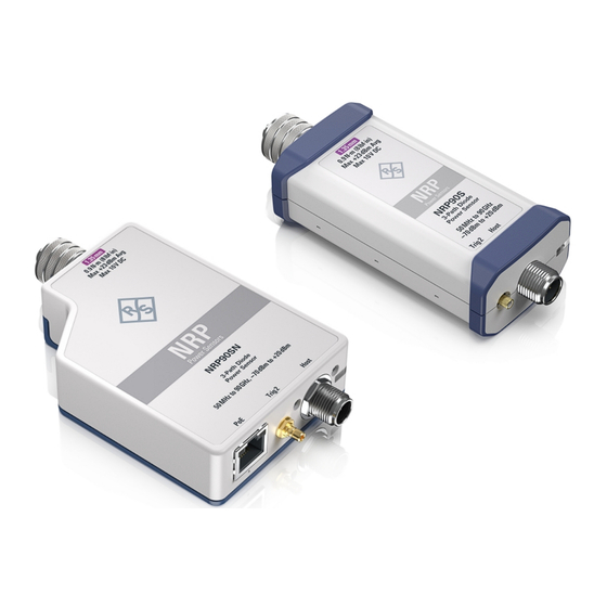
® Sensor tour R&S NRPxxS(N) RF connector 4 Sensor tour This section provides an overview of the available connectors and LEDs of the sensor. In the following figure, the USB sensor is shown on the left, the LAN sensor is shown on the right. -
Page 31: Status Information
® Sensor tour R&S NRPxxS(N) Status information Table 4-1: R&S NRPxxS(N) RF connector characteristics Model Male connector Matching female con- Tightening torque nector R&S NRP8S R&S NRP8SN 1.36 Nm (12'' lbs) R&S NRP18S R&S NRP18SN R&S NRP33S R&S NRP33SN 3.50 mm 3.50 mm/ 2.92 mm/ SMA R&S NRP33SN-V R&S NRP40S... -
Page 32: Host Interface
® Sensor tour R&S NRPxxS(N) LAN PoE interface Color Illumination State Turquoise Steady Zeroing is in progress. blue Slow flashing Static error Fast flashing Critical static error Note: If this state occurs after a firmware update, the update was not successful. Perform the firm- ware update again. - Page 33 ® Sensor tour R&S NRPxxS(N) LAN PoE interface LAN reset button The LAN reset button is used for resetting the Ethernet connection parameters of the sensor to their default values. Power over Ethernet status LED The power status LED shows whether the sensor is correctly powered over PoE or not. Indication State Green...
-
Page 34: Operating Concepts
® Operating concepts R&S NRPxxS(N) R&S NRP‑Toolkit 5 Operating concepts For operating the sensor, you can choose from various possibilities: ● Chapter 5.1, "R&S NRP‑Toolkit", on page 34 ● Chapter 5.2, "Web user interface", on page 37 ● Chapter 5.3, "Remote control", on page 38 ●... -
Page 35: R&S Nrp-Toolkit For Windows
® Operating concepts R&S NRPxxS(N) R&S NRP‑Toolkit For supported Microsoft Windows versions, see the release notes. 5.1.3 R&S NRP‑Toolkit for Windows The R&S NRP‑Toolkit installer for Windows-based systems contains the components described in the release notes. To install the R&S NRP‑Toolkit 1. - Page 36 ® Operating concepts R&S NRPxxS(N) R&S NRP‑Toolkit To uninstall the R&S NRP‑Toolkit Use the Windows functionality for removing apps and features. The R&S NRP‑Toolkit itself has no own uninstall functionality. 5.1.3.1 Components of the R&S NRP‑Toolkit Access: "Start" > "NRP-Toolkit" The following tools are part of the R&S NRP‑Toolkit for Windows.
-
Page 37: Web User Interface
® Operating concepts R&S NRPxxS(N) Web user interface 5.2 Web user interface Requires a sensor with networking capabilities, a LAN sensor. With the integrated, web user interface of the LAN sensor, you can easily configure the most common settings and measure in the provided measurement modes. There is no installation required. -
Page 38: Remote Control
® Operating concepts R&S NRPxxS(N) R&S NRPV The main dialog of the web user interface opens. 3. Select the "Continuous Average" tab and perform any necessary changes. 4. Press "Measurement > ON" to start the measurement. For a detailed description of the web user interface, refer to Chapter 6, "Web user interface", on page 44. - Page 39 ® Operating concepts R&S NRPxxS(N) R&S NRPV ● R&S NRP‑ZKU or R&S NRP‑ZKC cable or an R&S NRP‑Z5 sensor hub and an R&S NRP‑ZK6 cable to connect the sensor to the computer ● Windows computer with installed: – Latest version of R&S NRP‑Toolkit. See Chapter 5.1, "R&S NRP‑Toolkit", on page 34.
-
Page 40: R&S Power Viewer
® Operating concepts R&S NRPxxS(N) R&S Power Viewer 5.5 R&S Power Viewer The R&S Power Viewer is software that simplifies many measurement tasks. The R&S Power Viewer is a separate standalone installation package. The installation package is provided on the Rohde & Schwarz website at: ●... -
Page 41: R&S Power Viewer Mobile
® Operating concepts R&S NRPxxS(N) R&S Power Viewer Mobile Starting a measurement For a detailed description, refer to the operating manual of the R&S Power Viewer. The manual is installed automatically during the installation of the R&S Power Viewer. 1. Start the R&S Power Viewer. 2. -
Page 42: R&S Nrx
® Operating concepts R&S NRPxxS(N) R&S NRX 5.7 R&S NRX In a measurement, the R&S NRX uses all sensor-dependent measurement functions and displays the results. Thus, you can configure both the measurement and the sen- sor. Required equipment ● R&S NRPxxS(N) ●... - Page 43 ® Operating concepts R&S NRPxxS(N) R&S NRX 2. Note: Turn off all measurement signals before zeroing. An active measurement signal during zeroing causes an error. a) Switch off the power of the signal source. b) Press the [Zero] key of the R&S NRX. c) Tap "Zero All Sensors".
-
Page 44: Web User Interface
® Web user interface R&S NRPxxS(N) Main dialog of the web user interface 6 Web user interface The web user interface is an alternative way to operate an LAN sensor. This section provides a description of the parameters used for setting a power mea- surement with the web user interface. -
Page 45: Setting The Unit
® Web user interface R&S NRPxxS(N) Setting the unit Parameter pane Displays the content selected in the navigation pane. Result pane Displays the measurement result for the selected measurement mode. It can display only a value or a graph, depending on the selected measurement mode. 6.2 Setting the unit If a parameter has a unit, the unit is displayed after the value. -
Page 46: Common Settings
® Web user interface R&S NRPxxS(N) Common settings Unit multiples Keyboard key micro nano For certain parameters, you can select a different representation, depending on the requirements. For example, for the representation of the trigger level, you can choose Watts, dBm or dBµV. To change the unit, you must specify the desired value together with the full new unit once. - Page 47 ® Web user interface R&S NRPxxS(N) Common settings Offset Groups the offset settings. <State> ← Offset Enables or disables the usage of the level offset. Remote command: [SENSe<Sensor>:]CORRection:OFFSet:STATe <Value> ← Offset Adds a fixed level offset in dB to account for external losses. Remote command: [SENSe<Sensor>:]CORRection:OFFSet S-Parameter...
-
Page 48: Measurement Modes
® Web user interface R&S NRPxxS(N) Measurement modes Remote command: [SENSe<Sensor>:]AVERage:COUNt [SENSe<Sensor>:]AVERage:COUNt:AUTO:RESolution [SENSe<Sensor>:]AVERage:COUNt:AUTO:NSRatio 6.4 Measurement modes Describes the parameters for the available measurement modes. ● Continuous average mode..................48 ● Burst average mode....................49 ● Timeslot mode......................49 ● Trace mode......................50 6.4.1 Continuous average mode Describes the parameters of the continuous average measurement. -
Page 49: Burst Average Mode
® Web user interface R&S NRPxxS(N) Measurement modes Smoothing Enables the smoothing filter, a steep-cut off digital lowpass filter. The filter reduces result fluctuations caused by modulation. Remote command: [SENSe<Sensor>:][POWer:][AVG:]SMOothing:STATe 6.4.2 Burst average mode Describes the parameters of the burst average measurement. Further information: ●... -
Page 50: Trace Mode
® Web user interface R&S NRPxxS(N) Measurement modes Further information: ● Chapter 9.6.3, "Timeslot measurement", on page 97 Detailed description of the timeslot mode and its remote commands Access: main dialog of the web user interface > navigation pane > "Timeslot" Number of Timeslots..................... -
Page 51: Settings
® Web user interface R&S NRPxxS(N) Settings Trace Time........................51 Trace Offset Time......................51 Trace Points........................51 Trace Time Sets the trace length. Remote command: [SENSe<Sensor>:]TRACe:TIME Trace Offset Time Sets the relative position of the trigger event in relation to the beginning of the trace measurement sequence. - Page 52 ® Web user interface R&S NRPxxS(N) Settings ● Chapter 9.10, "Calibrating, zeroing", on page 131 ● Chapter 9.11, "Testing", on page 133 Access: main dialog of the web user interface > navigation pane > "Sensor" Range..........................52 Γ Correction........................52 └ <State>......................52 └...
-
Page 53: Averaging Settings
® Web user interface R&S NRPxxS(N) Settings Zero Calibration Performs zeroing using the signal at the sensor input. See Chapter 9.10, "Calibrating, zeroing", on page 131. Note: Turn off all test signals before zeroing. An active test signal during zeroing causes an error. -
Page 54: Trigger Settings
® Web user interface R&S NRPxxS(N) Settings Remote command: [SENSe<Sensor>:]AVERage:TCONtrol Auto Measurement Time Available only if "Noise Content" is set under "<Mode>" on page 47. Sets an upper limit for the settling time of the auto-averaging filter, thus limiting the length of the filter. -
Page 55: System Settings
® Web user interface R&S NRPxxS(N) Settings "Positive" The rising edge of the trigger signal is used for triggering. The falling edge of the trigger signal is used for triggering. "Negative" Remote command: TRIGger:SLOPe Trigger Level Sets the trigger threshold for internal triggering derived from the test signal. Remote command: on page 89 TRIGger:LEVel... -
Page 56: Ip Address
® Web user interface R&S NRPxxS(N) Settings Address........................56 Subnet Mask......................... 56 Sensor Name........................ 56 Gateway........................56 DHCP..........................56 Selftest.......................... 57 Apply Network Settings....................57 Firmware Update......................58 RST..........................58 Reboot...........................58 IP Address Sets the IP address of the sensor. Remote command: SYSTem:COMMunicate:NETWork:IPADdress Subnet Mask Sets the subnet mask. -
Page 57: Selftest
® Web user interface R&S NRPxxS(N) Settings "Auto" Assigns the IP address automatically, provided the network supports DHCP (dynamic host configuration protocol). "Static" Enables assigning the IP address manually. Remote command: SYSTem:COMMunicate:NETWork:IPADdress:MODE Selftest Starts a self-test of the sensor. See also Chapter 9.11, "Testing", on page 133. -
Page 58: Firmware Update
® Web user interface R&S NRPxxS(N) Settings Firmware Update Opens a dialog to start the firmware update. For further information, see Chapter 7.2.2, "Using the web user interface", on page 61. Alternatively, you can the Firmware Update program. See Chapter 7.2.1, "Using the Firmware Update program", on page 59. -
Page 59: Firmware Update
® Firmware update R&S NRPxxS(N) Updating the firmware 7 Firmware update ● Downloading the firmware update file..............59 ● Updating the firmware..................... 59 7.1 Downloading the firmware update file Firmware update files of R&S sensors generally have an RSU extension, RSU mean- ing Rohde &... - Page 60 ® Firmware update R&S NRPxxS(N) Updating the firmware To check the prerequisites 1. Ensure that a recent VISA software is installed on the computer. The latest version is provided on the Rohde & Schwarz website at www.rohde- schwarz.com/rsvisa. 2. Ensure that the R&S NRP‑Toolkit for Windows is installed on the computer. See Chapter 5.1, "R&S NRP‑Toolkit", on page 34.
-
Page 61: Using The Web User Interface
® Firmware update R&S NRPxxS(N) Updating the firmware During the update process, a progress bar is displayed. The update sequence can take a couple of minutes, depending on the sensor model and the size of the selected file. 8. Check if the update was successful. The firmware version in the "Identification" field must match the version you selected in the "Firmware"... -
Page 62: Using Ftp
® Firmware update R&S NRPxxS(N) Updating the firmware 4. Click "Firmware Update". 5. In the "Firmware Update" dialog, click "Select RSU file". 6. In the file browser, select the RSU file for upload. The selected RSU file is displayed, for example NRPxSN_02.30.21062301.rsu. 7. -
Page 63: Using Remote Control
® Firmware update R&S NRPxxS(N) Updating the firmware 6. Copy the new RSU file into the directory. When the copying process is completed, the firmware update starts automatically. The files in the update directory are deleted automatically at every reboot. 7.2.4 Using remote control If you want to integrate a firmware update function in an application, use SYSTem:... -
Page 64: Replacing An R&S Nrp-Zxx With A Sensor
® Replacing an R&S NRP‑Zxx with a sensor R&S NRPxxS(N) How to proceed 8 Replacing an R&S NRP‑Zxx with a sensor The NRP sensors are compatible with the R&S NRP‑Zxx sensors. R&S NRPxxS(N) Replaces R&S NRP‑Zxx sensor R&S NRP8S / R&S NRP8SN - USB connected R&S NRP-Z11 R&S NRP18S / R&S NRP18SN - USB connected R&S NRP-Z21... - Page 65 ® Replacing an R&S NRP‑Zxx with a sensor R&S NRPxxS(N) How to proceed After the new version of the R&S NRP‑Toolkit is installed, you can connect the R&S NRPxxS(N) to the computer and use it with Rohde & Schwarz software applica- tions or your own programs.
-
Page 66: Remote Control Commands
® Remote control commands R&S NRPxxS(N) Conventions used in SCPI command descriptions 9 Remote control commands In the following, all implemented commands are listed according to the command sys- tem and then described in detail. Mostly, the notation used complies with SCPI specifi- cations. -
Page 67: Notations
® Remote control commands R&S NRPxxS(N) Notations Table 9-1: SCPI prefixes Factor SI name SI symbol SCPI prefix kilo mega MA; also allowed are MOHM and MHZ giga tera milli Exception: Hz and Ohm μ micro nano pico 9.2 Notations For a detailed description of SCPI notations, see Chapter 11, "Remote control basics",... -
Page 68: Common Commands
® Remote control commands R&S NRPxxS(N) Common commands Example: Command [SENSe<Sensor>:][POWer:][AVG:]SMOothing:STATe 1 can be writ- ten as: SENSe1:POWer:AVG:SMOothing:STATe 1 SENS:POW:AVG:SMO:STAT 1 SENSe:POWer:SMOothing:STATe 1 SENSe:SMOothing:STATe 1 SMOothing:STATe 1 SMO:STAT 1 Parameters Parameters are separated from the header by a "white space". If several parameters are specified in a command, they are separated by a comma. -
Page 69: Cls
® Remote control commands R&S NRPxxS(N) Common commands ..........................71 *SAV ..........................71 *SRE ..........................71 *STB? ..........................71 *TRG ..........................72 *TST? ..........................72 *WAI *CLS Clear status Resets the following: ● Status byte (STB) ● Standard event register (ESR) ● EVENt part of the QUEStionable and the OPERation register ●... -
Page 70: Ist
® Remote control commands R&S NRPxxS(N) Common commands *IST? Individual status Returns the current value of the IST flag in decimal form. The IST flag is the status bit which is sent during a parallel poll. Usage: Query only *OPC Operation complete Sets bit 0 in the event status register when all preceding commands have been execu- ted. -
Page 71: Rst
® Remote control commands R&S NRPxxS(N) Common commands Usage: Setting only *RST Reset Sets the instrument to a defined default status. The default settings are indicated in the description of commands. The command corresponds to the command. SYSTem:PRESet Usage: Event Manual operation: "RST"... -
Page 72: Preparing For The Measurement
® Remote control commands R&S NRPxxS(N) Preparing for the measurement TRIGger:SOURce BUS. Usage: Event *TST? Self-test Triggers a self-test of the sensor and outputs the result. 0 indicates that no errors have occurred. Usage: Query only *WAI Wait to continue Prevents the execution of the subsequent commands until all preceding commands have been executed and all signals have settled. -
Page 73: Selecting A Measurement Path
® Remote control commands R&S NRPxxS(N) Preparing for the measurement *RST: If the sensor boots or reboots, the source is set to INTernal. If the sensor is reset, the source setting is kept unchanged. Example: ROSC:SOUR INT 9.4.2 Selecting a measurement path The RANGe subsystem contains commands for selection of a measurement path. -
Page 74: Selecting A Measurement Mode
® Remote control commands R&S NRPxxS(N) Preparing for the measurement Suffix: <Sensor> Parameters: <level> Range: -20.00 dB to 0.00 dB *RST: 0.00 dB Default unit: dB 9.4.3 Selecting a measurement mode ► Before starting a measurement, select the measurement mode using: [SENSe<Sensor>:]FUNCtion The available measurement modes and how to configure them are described in Chapter 9.6, "Configuring the measurement... - Page 75 ® Remote control commands R&S NRPxxS(N) Preparing for the measurement CALCulate:FEED <mode> If you query measurement data using FETCh<Sensor>[:SCALar][:POWer][: AVG]?, the sensor returns data of the measurand that was configured before. Gener- ally, this measurand is the average power. However, the sensor can also output data of other measurands.
-
Page 76: Controlling The Measurement
® Remote control commands R&S NRPxxS(N) Controlling the measurement Example: The following sequence of commands configures a peak trace measurement: *RST SENSe:FUNCtion "XTIMe:POWer" SENSe:FREQuency 1.0e9 SENSe:TRACe:POINts 500 SENS:TRAC:TIME 20e-3 TRIGger:SOURce INTernal TRIGger:SLOPe POSitive TRIGger:DTIMe 0.001 TRIGger:HYSTeresis 0.1 TRIGger:LEVel 30e-6 SENSe:TRACe:AVERage:COUNt 8 SENSe:TRACe:AVERage:STATe ON CALCulate:FEED "POWer:PEAK:TRACe"... -
Page 77: Starting And Ending A Measurement
® Remote control commands R&S NRPxxS(N) Controlling the measurement ● Do you want to output each new average value as a measurement result or do you want to bundle more measured values into one result? 9.5.1 Starting and ending a measurement .......................... -
Page 78: Triggering
® Remote control commands R&S NRPxxS(N) Controlling the measurement Measurements are performed continuously. If a measurement is completed, the sensor does not return to the idle state but enters the waiting for trigger state again. Ends the continuous measurement mode, and sets the sensor to the idle state. - Page 79 ® Remote control commands R&S NRPxxS(N) Controlling the measurement ● INITiate[:IMMediate] The number of measurement cycles is restricted. 1 is set, the command starts a single measurement cycle that TRIGger:COUNt renders one result. Every time you send this command, a new measurement cycle is started.
- Page 80 ® Remote control commands R&S NRPxxS(N) Controlling the measurement Figure 9-1: Significance of the dropout time 1 = Dropout time 2 = Trigger hysteresis 3 = Trigger level The RF power between the slots is below the threshold defined by the trigger level and the trigger hysteresis.
-
Page 81: Controlling The Measurement Results
® Remote control commands R&S NRPxxS(N) Controlling the measurement 1 = Holdoff time 2 = Trigger hysteresis 3 = Trigger level 9.5.3 Controlling the measurement results The sensor can cope with the wide range of measurement scenarios with the help of the so-called "termination control". -
Page 82: Interplay Of The Controlling Mechanisms
® Remote control commands R&S NRPxxS(N) Controlling the measurement 9.5.4 Interplay of the controlling mechanisms In the following examples, continuous measurement scenarios are used. But these scenarios also apply to single measurements. The only difference is that a single mea- surement is not repeated. - Page 83 ® Remote control commands R&S NRPxxS(N) Controlling the measurement Example: Moving termination control Further settings for this example: ● [SENSe<Sensor>:]AVERage:TCONtrol MOVing ● TRIGger:COUNt Every measurement is started by a trigger event. Due to the chopper phases, one measurement lasts twice the defined aperture time. During each measurement, the trigger synchronization is high (TRIGger:SYNC:STATe ON).
- Page 84 ® Remote control commands R&S NRPxxS(N) Controlling the measurement Example: Average count = 1 [SENSe<Sensor>:]AVERage:COUNt For average count 1, the setting of the termination control has no impact. In both cases, the measurement runs for the duration of one aperture time. Then, settled data is available, and the sensor returns to the idle state.
- Page 85 ® Remote control commands R&S NRPxxS(N) Controlling the measurement Example: Moving termination control Further settings for this example: ● [SENSe<Sensor>:]TRACe:AVERage:TCONtrol MOVing Every chopper phase is started by a trigger event and lasts the defined trace time. Dur- ing a chopper phase, the trigger synchronization is high (TRIGger:SYNC:STATe ON).
-
Page 86: Configuring The Trigger
® Remote control commands R&S NRPxxS(N) Controlling the measurement 9.5.5 Configuring the trigger Further information: ● Chapter 9.5, "Controlling the measurement", on page 76 Remote commands: ....................86 TRIGger:ATRigger:DELay ..................86 TRIGger:ATRigger:EXECuted? ....................87 TRIGger:ATRigger[:STATe] ......................87 TRIGger:COUNt ....................... 87 TRIGger:DELay ..................... 87 TRIGger:DELay:AUTO ....................... -
Page 87: Trigger:atrigger[:State]
® Remote control commands R&S NRPxxS(N) Controlling the measurement TRIGger:ATRigger[:STATe] <state> Effective only in trace mode and, irrespective of the set averaging factor, only one trace is recorded. Controls the automatic trigger function. If enabled, an artificial trigger is generated if the delay time has elapsed after the measurement start, and no trigger event has occur- red. -
Page 88: Trigger:dtime
® Remote control commands R&S NRPxxS(N) Controlling the measurement If a longer period is set using TRIGger:DELay, the automatically determined delay is ignored. Parameters: <state> *RST: TRIGger:DTIMe <dropout_time> Sets the dropout time for the internal trigger source. During this time, the signal power must exceed (negative trigger slope) or undercut (positive trigger slope) the level defined by the trigger level and trigger hysteresis. -
Page 89: Trigger:hysteresis
® Remote control commands R&S NRPxxS(N) Controlling the measurement TRIGger:HYSTeresis <hysteresis> Sets the hysteresis. A trigger event occurs, if the trigger level: ● Falls below the set value on a rising slope. ● Rises above the set value on a falling slope Thus, you can use this setting to eliminate the effects of noise in the signal for the edge detector of the trigger system. -
Page 90: Trigger:sender:port
® Remote control commands R&S NRPxxS(N) Controlling the measurement Parameters: <unit> DBM | W | DBUV *RST: Manual operation: "Trigger Level" on page 55 TRIGger:SENDer:PORT <sender_port> Selects the port where the sensor outputs its own trigger event in case it is the trigger sender. -
Page 91: Trigger:source
® Remote control commands R&S NRPxxS(N) Controlling the measurement POSitive Rising edge NEGative Falling edge *RST: POSitive Manual operation: "<Slope>" on page 54 TRIGger:SOURce <source> Selects the source for the trigger event detector. Parameters: <source> HOLD | IMMediate | INTernal | BUS | EXTernal | EXT1 | EXTernal1 | EXT2 | EXTernal2 Chapter 9.5.2.3, "Trigger sources",... -
Page 92: Configuring The Measurement Modes
® Remote control commands R&S NRPxxS(N) Configuring the measurement modes During the measurement, the trigger synchronization is high. For a continuous average measurement, the measurement time is calculated as described in Chapter 9.6.1.4, "Calculating the measurement time", on page 93. For a trace or timeslot measurement, one measurement cycle is one sweep. - Page 93 ® Remote control commands R&S NRPxxS(N) Configuring the measurement modes Manual operation: "Aperture Time" on page 48 9.6.1.2 Reducing noise and zero offset The smoothing filter can reduce result fluctuations caused by modulation. But activat- ing it increases the inherent noise of the sensor by approx. 20 %, so do not activate if it unless required.
- Page 94 ® Remote control commands R&S NRPxxS(N) Configuring the measurement modes MT: overall measurement time AC: average count APER: aperture time 100 μs is the time for switching the chopper phase. 9.6.1.5 Accelerating measurements Using ON, you can accelerate the mea- [SENSe<Sensor>:][POWer:][AVG:]FAST surement as follows: ●...
- Page 95 ® Remote control commands R&S NRPxxS(N) Configuring the measurement modes 9.6.1.6 Configuring the result buffer ............... 95 [SENSe<Sensor>:][POWer:][AVG:]BUFFer:CLEar ............95 [SENSe<Sensor>:][POWer:][AVG:]BUFFer:COUNt? ..............95 [SENSe<Sensor>:][POWer:][AVG:]BUFFer:SIZE ...............95 [SENSe<Sensor>:][POWer:][AVG:]BUFFer:STATe [SENSe<Sensor>:][POWer:][AVG:]BUFFer:CLEar Clears the contents of the result buffer. Suffix: <Sensor> Example: BUFF:CLE Usage: Event [SENSe<Sensor>:][POWer:][AVG:]BUFFer:COUNt? Queries the number of results that are currently stored in the result buffer. Suffix: <Sensor>...
-
Page 96: Burst Average Measurement
® Remote control commands R&S NRPxxS(N) Configuring the measurement modes Suffix: <Sensor> Parameters: <state> ON | OFF *RST: Example: BUFF:STAT OFF 9.6.2 Burst average measurement The burst average mode is used to measure the average power of bursts. The integra- tion time of a measurement is not predefined but determined by the sensor with the aid of a burst detector. -
Page 97: Timeslot Measurement
® Remote control commands R&S NRPxxS(N) Configuring the measurement modes Suffix: <Sensor> Parameters: <tolerance> Range: 0.00 s to 0.30 s *RST: 1.000e-6 s Default unit: s Manual operation: "Dropout Tolerance" on page 49 9.6.2.2 Defining a time interval for the measurement At the beginning and at the end of the measurement interval, you can define time inter- vals that are excluded from the measurement, see Chapter 9.7.3, "Excluding... - Page 98 ® Remote control commands R&S NRPxxS(N) Configuring the measurement modes Timeslot 1 Timeslot 2 Timeslot 3 Trigger event Trigger level Time Timeslot width Start of fence Length of fence Figure 9-3: Timeslot parameters For information on querying the measurement results, see Chapter 9.9.3, "Timeslot measurement results",...
- Page 99 ® Remote control commands R&S NRPxxS(N) Configuring the measurement modes Suffix: <Sensor> Parameters: <count> Range: 1 to 128 *RST: Manual operation: "Number of Timeslots" on page 50 [SENSe<Sensor>:][POWer:]TSLot[:AVG]:WIDTh <width> Sets the length of the timeslot. See Figure 9-3. Suffix: <Sensor> Parameters: <width>...
-
Page 100: Trace Measurement
® Remote control commands R&S NRPxxS(N) Configuring the measurement modes [SENSe<Sensor>:][POWer:]TSLot[:AVG][:EXCLude]:MID[:STATe] <state> Enables or disables the blanking out of time intervals in the timeslots. Suffix: <Sensor> Parameters: <state> *RST: 9.6.4 Trace measurement The trace measurement determines the course of power over a defined time. During the measurement time set by [SENSe<Sensor>:]TRACe:TIME, a large number of measurements are performed. - Page 101 ® Remote control commands R&S NRPxxS(N) Configuring the measurement modes [SENSe<Sensor>:]TRACe:AVERage:TCONtrol <mode> Defines how the measurement results are output. This is called termination control. See also Chapter 9.5, "Controlling the measurement", on page 76. Suffix: <Sensor> Parameters: <mode> MOVing | REPeat MOVing Outputs intermediate values to facilitate early detection of changes in the measured quantity.
- Page 102 ® Remote control commands R&S NRPxxS(N) Configuring the measurement modes [SENSe<Sensor>:]TRACe:OFFSet:TIME <time> Adds an offset to the beginning of the trace sequence. Thus, the trace in the result dis- play is moved in the positive or negative x-direction. If you measure with more than one sensor, you can use this offset to arrange the traces to each other.
-
Page 103: Configuring Basic Measurement Parameters
® Remote control commands R&S NRPxxS(N) Configuring basic measurement parameters [SENSe<Sensor>:]TRACe:TIME <time> Sets the trace length, time to be covered by the trace sequence. This time period is divided into several equal intervals, in which the average power is determined. The number of intervals equals the number of trace points, which is set using [SENSe<Sensor>:]TRACe:POINts. - Page 104 ® Remote control commands R&S NRPxxS(N) Configuring basic measurement parameters Suffix: <Sensor> Parameters: <count> Range: 1 to 65536 *RST: Example: AVER:COUN 1 Manual operation: "<Value>" on page 47 [SENSe<Sensor>:]AVERage:COUNt:AUTO <state> Sets how the average count is determined. Suffix: <Sensor> Parameters: <state>...
- Page 105 ® Remote control commands R&S NRPxxS(N) Configuring basic measurement parameters [SENSe<Sensor>:]AVERage:COUNt:AUTO:NSRatio <nsr> Determines the relative noise component in the measurement result for the measure- ment modes with scalar results. These measurement modes are continuous average, burst average and timeslot, provided the particular sensor supports them. This command is only effective if the auto average calculation is enabled: ●...
- Page 106 ® Remote control commands R&S NRPxxS(N) Configuring basic measurement parameters Parameters: <slot> Range: 1 to 128 *RST: [SENSe<Sensor>:]AVERage:RESet Deletes all previous measurement results that the averaging filter contains and initial- izes the averaging filter. The filter length gradually increases from 1 to the set averag- ing factor.
-
Page 107: Setting The Frequency
® Remote control commands R&S NRPxxS(N) Configuring basic measurement parameters [SENSe<Sensor>:]AVERage:TCONtrol <mode> Defines how the measurement results are output. This is called termination control. See also Chapter 9.5, "Controlling the measurement", on page 76. Suffix: <Sensor> Parameters: <mode> MOVing | REPeat MOVing Outputs intermediate values to facilitate early detection of changes in the measured quantity. -
Page 108: Excluding Intervals
® Remote control commands R&S NRPxxS(N) Configuring basic measurement parameters The center frequency is set for broadband signals, e.g. spread spectrum signals, multi- carrier signals. Suffix: <Sensor> Parameters: <frequency> Range: 0.0 Hz to Depends on the model. See the specifi- cations document. -
Page 109: Configuring Corrections
® Remote control commands R&S NRPxxS(N) Configuring basic measurement parameters Sets a time interval at the beginning of bursts that is excluded from the measurement. Figure 9-4. Suffix: <Sensor> Parameters: <exclude_start> Range: 0.0 s to 1.0 s *RST: 0.0 s Default unit: s Manual operation: "Start Exclude"... - Page 110 ® Remote control commands R&S NRPxxS(N) Configuring basic measurement parameters Remote commands: ................110 [SENSe<Sensor>:]CORRection:DCYCle ..............110 [SENSe<Sensor>:]CORRection:DCYCle:STATe [SENSe<Sensor>:]CORRection:DCYCle <duty_cycle> Available in continuous average mode. Sets the duty cycle for measuring pulse-modulated signals. The duty cycle defines the percentage of one period during which the signal is active. If the duty cycle is enabled, the sensor considers this percentage when calculating the signal pulse power from the average power.
- Page 111 ® Remote control commands R&S NRPxxS(N) Configuring basic measurement parameters [SENSe<Sensor>:]CORRection:OFFSet <offset> Sets a fixed offset that is added to correct the measured value. Suffix: <Sensor> Parameters: <offset> Range: -200.00 dB to 200.00 dB *RST: 0 dB Default unit: dB Manual operation: "<Value>"...
- Page 112 ® Remote control commands R&S NRPxxS(N) Configuring basic measurement parameters [SENSe<Sensor>:]CORRection:SPDevice:LIST? Queries the list of the S-parameter data sets that have been downloaded to the sensor. Returns the consecutive number and mnemonic of each data set. Suffix: <Sensor> Usage: Query only [SENSe<Sensor>:]CORRection:SPDevice:SELect <num>...
- Page 113 ® Remote control commands R&S NRPxxS(N) Configuring basic measurement parameters The complex reflection coefficient Γ of the sensor, which is also required for the sensor correction, is prestored in the calibration data memory for many frequencies. Sensor Source Figure 9-5: Correction of interactions between the sensor and the signal source If the gamma correction is performed in combination with an S-parameter correction ([SENSe<Sensor>:]CORRection:SPDevice:STATe ON), the following is consid-...
- Page 114 ® Remote control commands R&S NRPxxS(N) Configuring basic measurement parameters [SENSe<Sensor>:]SGAMma:MAGNitude <magnitude> Sets the magnitude of the complex reflection coefficient of the source, Γ source Suffix: <Sensor> Parameters: 0.0 ≙ ideal matched source <magnitude> 1.0 ≙ total reflection Range: 0.0 to 1.0 *RST: Manual operation: "Magnitude"...
- Page 115 ® Remote control commands R&S NRPxxS(N) Configuring basic measurement parameters Example: IGAM:MAGN? Query 1.739179E-02 Response Usage: Query only [SENSe<Sensor>:]IGAMma:PHASe? Queries the phase angle of the complex input reflection coefficient Γ . The result is provided in degrees. Range: -180 degrees to +180 degrees. Suffix: <Sensor>...
- Page 116 ® Remote control commands R&S NRPxxS(N) Configuring basic measurement parameters User interface of the S-Parameters program Figure 9-7: S-Parameters dialog Menu bar........................117 └ File........................ 117 └ Sensor......................117 └ Device......................117 └ Options......................117 └ User Data....................117 └ Remote....................117 └ Show Cal.
- Page 117 ® Remote control commands R&S NRPxxS(N) Configuring basic measurement parameters Menu bar Contains the following submenus. File ← Menu bar Provides options for loading and saving calibration data files, see: ● "To change the S-parameter data" on page 121 ● "To load an uncertainty parameter file"...
- Page 118 ® Remote control commands R&S NRPxxS(N) Configuring basic measurement parameters You can copy the text output to the clipboard by clicking "Copy to Clipboard." Figure 9-8: Example Global Flags Groups the settings for the sensor behavior regarding S-parameter corrections. S-Parameter Correction ON by Default ← Global Flags If this option is enabled, the S-parameter correction is activated automatically when the sensor is started.
- Page 119 ® Remote control commands R&S NRPxxS(N) Configuring basic measurement parameters Use Flags in Factory Cal. Data Set ← Global Flags Available if the sensor supports two different calibration data sets: ● Factory calibration data set containing all factory calibration data. ●...
- Page 120 ® Remote control commands R&S NRPxxS(N) Configuring basic measurement parameters The "Upload Calibration Data" dialog opens. It shows a list of the available sen- sors. 3. If you cannot find your sensor in the list, for example because of reconnecting the sensor, you can reload the list by clicking "Rebuild List".
- Page 121 ® Remote control commands R&S NRPxxS(N) Configuring basic measurement parameters 6. Create a backup of the calibration data set before making any changes. Select "File" > "Save Calibration Data". A dialog opens where you can select the location to save the calibration data. To change the S-parameter data 1.
- Page 122 ® Remote control commands R&S NRPxxS(N) Configuring basic measurement parameters 5. If needed, load uncertainty data. See "To load an uncertainty parameter file" on page 122. 6. Check the entries in the "S-Parameter Device Mnemonic", "Lower Power Limit/W" and "Upper Power Limit/W" fields 7.
- Page 123 ® Remote control commands R&S NRPxxS(N) Configuring basic measurement parameters To save the calibration data on the sensor 1. Select "Sensor" > "Save Calibration Data". The "Download Calibration Data" dialog opens. 2. Confirm that the correct sensor is selected by clicking "Download". After a successful transfer of the data to the sensor, a confirmation message is dis- played.
- Page 124 ® Remote control commands R&S NRPxxS(N) Configuring basic measurement parameters ● Option line The option line has the format #[<frequency unit>][<parameter>][<format>][<R n>], where: – Identifies the option line. – <frequency unit> Possible values are Hz, kHz, MHz or GHz. If a frequency unit is not specified, GHz is implicitly assumed.
-
Page 125: Configuring Measurement Results
® Remote control commands R&S NRPxxS(N) Configuring measurement results – <parameter> U must be specified for uncertainty data files. If a parameter is not specified, S is implicitly assumed and as a result an error message is triggered. – <format> This value is ignored in uncertainty measurement files. -
Page 126: Setting The Result Format
® Remote control commands R&S NRPxxS(N) Configuring measurement results 9.8.2 Setting the result format The FORMat subsystem sets the format of numeric data (measured values) that is exchanged between the remote control computer and the sensors if high-level mea- surement commands are used. Remote commands: ......................126 FORMat:BORDer... -
Page 127: Querying Measurement Results
® Remote control commands R&S NRPxxS(N) Querying measurement results 32 | 64 32-bit or 64-bit If you omit the length, the sensor sets the last used length. Example for REAL,32 format: #6768000..<binary float values>..Example for REAL,64 format: #71536000..<binary float values>..<data[,length]>... -
Page 128: Burst Average Measurement Results
® Remote control commands R&S NRPxxS(N) Querying measurement results To configure the measurand, use before the measurement is initi- CALCulate:FEED ated. Suffix: <Sensor> Usage: Query only [SENSe<Sensor>:][POWer:][AVG:]BUFFer:DATA? Queries the results of the continuous average result buffer and returns them even if the buffer is not full. -
Page 129: Trace Measurement Results
® Remote control commands R&S NRPxxS(N) Querying measurement results 9.9.4 Trace measurement results [SENSe<Sensor>:]TRACe:DATA? Returns the measured trace data in a well-defined format, showing the course of power over a defined time. Unlike FETCh<Sensor>[:SCALar][:POWer][:AVG]?, this command takes the set- tings of into account, as explained below. - Page 130 ® Remote control commands R&S NRPxxS(N) Querying measurement results In the further description, the term "user data content" is used for the totality of the con- tained measurement results. In the user data content, there are similar mechanisms as with arbitrary block response data.
-
Page 131: Calibrating, Zeroing
® Remote control commands R&S NRPxxS(N) Calibrating, zeroing Usage: Query only 9.10 Calibrating, zeroing Zeroing removes offset voltages from the analog circuitry of the sensor, so that there are only low powers displayed if no power applied. The zeroing process can take more than 8 s to complete. - Page 132 ® Remote control commands R&S NRPxxS(N) Calibrating, zeroing CALibration:USER:DATA <caldata> Transfers the user calibration data set, which mainly contains S-parameter sets for user-specific devices. The query returns the data as it was downloaded to the sensor before. After downloading of a new user calibration data set to the sensor, the current S- parameter correction settings become invalid.
-
Page 133: Testing
® Remote control commands R&S NRPxxS(N) Configuring the system Example: *CLS CAL1:ZERO:AUTO ONCE Performs zeroing. Takes several seconds. SYST:SERR? Query -240 Response: Warning; Zero Calibration failed; Results Degrading. Manual operation: "Zero Calibration" on page 53 9.11 Testing The self-test allows a test of the internal circuitry of the sensor. Do not apply a signal to the sensor while the self-test is running. -
Page 134: Reboot And Restart
® Remote control commands R&S NRPxxS(N) Configuring the system INITiate:CONTinuous SENSe:AVERage:TCONtrol SENSe:TRACe:AVERage:TCONtrol Usage: Event SYSTem:INITialize Sets the sensor to the standard state, i.e. the default settings for all test parameters are loaded in the same way as with *RST. The sensor then outputs a complete list of all supported commands and parameters. -
Page 135: Password Management
® Remote control commands R&S NRPxxS(N) Configuring the system Definite length arbitrary block data containing the direct copy of the binary *.rsu file in the following format: Single digit indicating how many digits follow to specify the size of the binary file. Number that specifies the size of the binary file. -
Page 136: Network Settings
® Remote control commands R&S NRPxxS(N) Configuring the system <passwd2> New security password, entered as a string. SYST:SEC:PASS:SEC "100095","100096" Example: Usage: Setting only SYSTem:SECurity:PASSword:USER <passwd1>, <passwd2> Sets a new user password, also called instrument password. The command is restricted to remote control over the USB interface (USBTMC). Setting parameters: <passwd1>... -
Page 137: System:communicate:network[:Common]:Hostname
® Remote control commands R&S NRPxxS(N) Configuring the system SYSTem:COMMunicate:NETWork[:COMMon]:HOSTname <hostname> Effective only for the LAN sensors. Sets the individual host name of the sensor. In a LAN that uses a DNS server (domain name system server), you can access each connected instrument using a unique host name instead of its IP address. -
Page 138: System:communicate:network:ipaddress
® Remote control commands R&S NRPxxS(N) Configuring the system SYSTem:COMMunicate:NETWork:IPADdress <ipaddress> Effective only: ● For the LAN sensors. ● is set to STATic. SYSTem:COMMunicate:NETWork:IPADdress:MODE Sets the IP address of the sensor. Parameters: <ipaddress> Example: SYST:COMM:NETW:IPAD '147.161.235.79' Sets 147.161.235.79 as IP address. Manual operation: "IP Address"... -
Page 139: System:communicate:network:ipaddress:subnet:mask
® Remote control commands R&S NRPxxS(N) Configuring the system *RST: AUTO SYST:COMM:NETW:IPAD:MODE AUTO Example: The IP address is assigned automatically. Manual operation: "DHCP" on page 56 SYSTem:COMMunicate:NETWork:IPADdress:SUBNet:MASK <netmask> Effective only: ● For the LAN sensors. ● is set to STATic. SYSTem:COMMunicate:NETWork:IPADdress:MODE Sets the subnet mask. -
Page 140: Remote Settings
® Remote control commands R&S NRPxxS(N) Configuring the system 9.12.6 Remote settings ....................140 SYSTem:HELP:HEADers? ....................140 SYSTem:HELP:SYNTax? ..................140 SYSTem:HELP:SYNTax:ALL? .......................140 SYSTem:LANGuage ....................141 SYSTem:PARameters? ..................141 SYSTem:PARameters:DELTa? ..................141 SYSTem:TRANsaction:BEGin .................... 141 SYSTem:TRANsaction:END ......................141 SYSTem:VERSion? SYSTem:HELP:HEADers? [<Item>] Returns a list of all SCPI commands supported by the sensor. Query parameters: <Item>... - Page 141 ® Remote control commands R&S NRPxxS(N) Configuring the system SYSTem:PARameters? Returns an XML-output containing all commands with the following information, if avail- able for the command: ● Default value ● Minimum value ● Maximum value ● Parameters ● Limits Each command is shortened to a command token, consisting only of the mnemonics short form.
-
Page 142: Sensor Information
® Remote control commands R&S NRPxxS(N) Configuring the system 9.12.7 Sensor information ..................142 SYSTem:DFPRint<Channel>? ................. 142 SYSTem:DFPRint:HISTory:COUNt? ................. 142 SYSTem:DFPRint:HISTory:ENTRy? ......................142 SYSTem:INFO? ....................143 SYSTem[:SENSor]:NAME SYSTem:DFPRint<Channel>? Reads the footprint file of the sensor. Suffix: <Channel> 1...4 Measurement channel if more than one channel is available. Usage: Query only SYSTem:DFPRint:HISTory:COUNt? -
Page 143: Status Display And Update
® Remote control commands R&S NRPxxS(N) Configuring the system Query parameters: <item> "Manufacturer", "Type", "Stock Number", "Serial", "SW Build", "Sensor Name", "Hostname", "IP Address", "Technology", "Func- tion", "MinPower", "MaxPower", "MinFreq", "MaxFreq", "Resolu- tion", "Impedance", "Coupling", "Cal. Due Date", "Cal. Abs.", "Cal. - Page 144 ® Remote control commands R&S NRPxxS(N) Configuring the system Sets the color and the flash code of the system status LED. Parameters: <color> Hexadecimal code is described as: 0x0krrggbb With k = 0: steady on; k = 1: slowly flashing; k = 2: fast flashing rr = red gg = green bb = blue...
-
Page 145: Measurement Limits And Levels
® Remote control commands R&S NRPxxS(N) Configuring the system SYSTem:SUTime <update_time> Effective only in the NRP legacy mode. Relevant only in continuous measurement mode, INITiate:CONTinuousON. Sets the status update time. The status update time is the maximum rate in which the sensor can output measurement results. -
Page 146: Errors
® Remote control commands R&S NRPxxS(N) Configuring the system 9.12.10 Errors See also Chapter 12.2, "Error messages", on page 179......................146 SYSTem:ERRor:ALL? ..................146 SYSTem:ERRor:CODE:ALL? ..................146 SYSTem:ERRor:CODE[:NEXT]? ....................147 SYSTem:ERRor:COUNt? ....................147 SYSTem:ERRor[:NEXT]? ......................147 SYSTem:SERRor? ................... 148 SYSTem:SERRor:LIST:ALL? ..................148 SYSTem:SERRor:LIST[:NEXT]? SYSTem:ERRor:ALL? Queries all unread entries in the SCPI communication error queue and removes them from the queue. - Page 147 ® Remote control commands R&S NRPxxS(N) Configuring the system Example: SYST:ERR:CODE? Query Response: No errors have occurred since the error queue was last read out. Usage: Query only SYSTem:ERRor:COUNt? Queries the number of entries in the SCPI communication error queue. Example: SYST:ERR:COUN? Query...
-
Page 148: Using The Status Register
® Remote control commands R&S NRPxxS(N) Using the status register SYSTem:SERRor:LIST:ALL? Queries all changes in the static error queue that have not been read yet and removes them from the queue. Example: SYST:SERR:LIST:ALL? Query 0,"reported at uptime:2942; notice; auto-averaging exceeded maximum time; Notification",0,"removed at uptime:2944;... -
Page 149: General Status Register Commands
® Remote control commands R&S NRPxxS(N) Using the status register 9.13.1 General status register commands ......................149 STATus:PRESet ....................149 STATus:QUEue[:NEXT]? STATus:PRESet Resets the edge detectors and ENABle parts of all registers to a defined value. Usage: Event STATus:QUEue[:NEXT]? Queries the most recent error queue entry and deletes it. Positive error numbers indicate sensor-specific errors. -
Page 150: Controlling The Enable Part
® Remote control commands R&S NRPxxS(N) Using the status register STATus:QUEStionable:CALibration[:SUMMary][:EVENt]? STATus:QUEStionable[:EVENt]? STATus:QUEStionable:POWer[:SUMMary][:EVENt]? STATus:QUEStionable:WINDow[:SUMMary][:EVENt]? Usage: Query only 9.13.4 Controlling the ENABle part STATus:DEVice:ENABle <value> STATus:OPERation:CALibrating:ENABle <value> STATus:OPERation:ENABle <value> STATus:OPERation:LLFail:ENABle <value> STATus:OPERation:MEASuring:ENABle <value> STATus:OPERation:SENSe:ENABle <value> STATus:OPERation:TRIGger:ENABle <value> STATus:OPERation:ULFail:ENABle <value> STATus:QUEStionable:CALibration:ENABle <value> STATus:QUEStionable:ENABle <value>... - Page 151 ® Remote control commands R&S NRPxxS(N) Using the status register STATus:OPERation:LLFail:PTRansition <value> STATus:OPERation:MEASuring:PTRansition <value> STATus:OPERation:SENSe:PTRansition <value> STATus:OPERation:TRIGger:PTRansition <value> STATus:OPERation:ULFail:PTRansition <value> STATus:QUEStionable:CALibration:PTRansition <value> STATus:QUEStionable:PTRansition <value> STATus:QUEStionable:POWer:PTRansition <value> STATus:QUEStionable:WINDow:PTRansition <value> Parameters: <value> *RST: 65535 User Manual 1177.5079.02 ─ 22...
-
Page 152: Performing Measurement Tasks - Programming Examples
® Performing measurement tasks - programming examples R&S NRPxxS(N) Performing the fastest measurement in continuous average mode 10 Performing measurement tasks - program- ming examples If you install the optional software development kit (SDK) of the R&S NRP‑Toolkit, pro- gramming examples are provided. See Chapter 5.1, "R&S NRP‑Toolkit", on page 34. - Page 153 ® Performing measurement tasks - programming examples R&S NRPxxS(N) Performing the fastest measurement in continuous average mode write( '*RST' ) # Enable fast unchopped continuous average measurement write( 'SENS:POW:AVG:FAST ON' ) # Define output format (float) write( 'FORM:DATA REAL,32' ) # Select the trigger condition.
-
Page 154: Triggered Fast Unchopped Continuous Average Measurement
® Performing measurement tasks - programming examples R&S NRPxxS(N) Performing the fastest measurement in continuous average mode 10.2.2 Triggered fast unchopped continuous average measurement This example, written in pseudo code, shows how to set up and execute a fast unchop- ped continuous average measurement. -
Page 155: Performing A Buffered Continuous Average Measurement
® Performing measurement tasks - programming examples R&S NRPxxS(N) Performing a buffered continuous average measurement # If there is any result in the buffer --> read it if ( query( 'BUFF:COUN?') > 0 ) result = queryBinary( 'BUFF:DATA?' ) numData = numData + result.size # Stop the continuous measurement utilDeviceIO.DeviceWrite( instrument, 'INIT:CONT OFF' ) 10.3 Performing a buffered continuous average measure-... - Page 156 ® Performing measurement tasks - programming examples R&S NRPxxS(N) Performing a buffered continuous average measurement // Buffer size is randomly selected to 17 SENSOR.write( "SENS:BUFF:SIZE 17" ); SENSOR.write( "SENS:BUFF:STAT ON" ); SENSOR.write( "TRIG:COUN 17" ); // Read out all errors / Clear error queue SENSOR.query( "SYST:ERR:ALL?", szBuf, sizeof( szBuf ) );...
-
Page 157: Performing Trace Measurements
® Performing measurement tasks - programming examples R&S NRPxxS(N) Performing trace measurements printf( szBuf ); 10.4 Performing trace measurements *RST //Set the sensor's operation mode to trace SENSe:FUNCtion "XTIMe:POWer" //Set the carrier frequency SENSe:FREQuency 1.8e9 //Set the number of points for the trace measurement //Using 500 points usually represents a good compromise //between USB transfer speed and resolution SENSe:TRACe:POINTs 500... -
Page 158: Trace Measurement With Synchronization To Measurement Complete
® Performing measurement tasks - programming examples R&S NRPxxS(N) Trace measurement with synchronization to measurement complete 10.5 Trace measurement with synchronization to measure- ment complete This example, written in pseudo code, shows how to set up and execute a trace mea- surement using a non-blocking technique. - Page 159 ® Performing measurement tasks - programming examples R&S NRPxxS(N) Trace measurement with synchronization to measurement complete // (this loop could also check for cancel-requests from the user or other break conditions) while ( ! bMeasReady ) query( "STAT:OPER:MEAS:EVEN?", &iEvent ); bMeasReady = ((iEvent &...
-
Page 160: Remote Control Basics
® Remote control basics R&S NRPxxS(N) Remote control interfaces and protocols 11 Remote control basics For general information on remote control of Rohde & Schwarz products via SCPI, refer to www.rohde-schwarz.com/rc-via-scpi. 11.1 Remote control interfaces and protocols For remote control, communication between the sensors and the controlling host is established based on various interfaces and protocols. - Page 161 ® Remote control basics R&S NRPxxS(N) Remote control interfaces and protocols USBTMC protocol USB Test & Measurement Class Specification (USBTMC) is a protocol that is built on top of USB for communication with USB devices from the test & measurement cate- gory.
-
Page 162: Ethernet Interface
® Remote control basics R&S NRPxxS(N) Remote control interfaces and protocols Model USB product ID R&S NRP90S, model 02 0x024C R&S NRP90S, model 03 R&S NRP90SN 0x026B Example: USB::0x0AAD::0x00E2::100001 0x0AAD is the vendor ID for Rohde & Schwarz. 0x00E2 is the product ID for the sensor. 100001 is the serial number of the particular sensor. -
Page 163: Status Reporting System
® Remote control basics R&S NRPxxS(N) Status reporting system You can also assign a LAN device name which defines the protocol characteristics of the connection. See the description of the VISA resource string below for the corre- sponding interface protocols. The string of the LAN device name is emphasized in ital- ics. -
Page 164: Overview
® Remote control basics R&S NRPxxS(N) Status reporting system registers and in the error queue. You can query both with the commands of the STATus subsystem. 11.2.1 Overview Fig.11-1 shows the hierarchical structure of information in the status registers. Status byte Error queue Device status Questionable status... -
Page 165: Device Status Register
® Remote control basics R&S NRPxxS(N) Status reporting system Table 11-3: Used status byte bits and their meaning Short description Bit is set if Device status register summary An instrument is connected or disconnected or when an error has occurred in an instrument, depending on the configuration of the instrument status register. - Page 166 ® Remote control basics R&S NRPxxS(N) Status reporting system Sum of bits 1 to 4 Measurement not possible Erroneous result Warning Critical Legacy locked state Reference PLL locked state Figure 11-2: Device status register Querying the register: ● STATus:DEVice:CONDition? ● STATus:DEVice[:EVENt]? Querying the static errors: ●...
-
Page 167: Questionable Status Register
® Remote control basics R&S NRPxxS(N) Status reporting system Bit no. Short description Bit is set if Legacy locked state The sensor is locked in the NRP legacy mode. Via the SCPI channels (USBTMC or TCP/IP), only query commands can be sent, but no setting commands. - Page 168 ® Remote control basics R&S NRPxxS(N) Status reporting system Power summary Calibration summary POST failure (self test) Figure 11-3: Questionable status register Querying the register: ● STATus:QUEStionable:CONDition? ● STATus:QUEStionable[:EVENt]? Table 11-5: Used questionable status bits and their meaning Bit no. Short description Bit is set if Power summary...
- Page 169 ® Remote control basics R&S NRPxxS(N) Status reporting system Sensor measurement corrupt Sensor zeroing needed Figure 11-4: Questionable power status register Querying the register: ● STATus:QUEStionable:POWer:CONDition? ● STATus:QUEStionable:POWer[:SUMMary][:EVENt]? Table 11-6: Used questionable power status bits and their meaning Bit no. Short description Bit is set if Sensor measurement corrupt...
-
Page 170: Standard Event Status And Enable Register (Esr, Ese)
® Remote control basics R&S NRPxxS(N) Status reporting system Sensor calibration failed Figure 11-5: Questionable calibration status register Querying the register: ● STATus:QUEStionable:CALibration:CONDition? ● STATus:QUEStionable:CALibration[:SUMMary][:EVENt]? Table 11-7: Used questionable calibration status bits and their meaning Bit no. Short description Bit is set if Sensor calibration failed Zeroing of the sensor was not successful. -
Page 171: Operation Status Register
® Remote control basics R&S NRPxxS(N) Status reporting system Operation Complete Query Error Device-Dependent Error Execution Error Command Error User Request Power On Figure 11-6: Standard event status register (ESR) Table 11-8: Used standard event status bits and their meaning Bit no. - Page 172 ® Remote control basics R&S NRPxxS(N) Status reporting system Calibrating Measuring Triggering Sense summary Lower limit fail Upper limit fail Figure 11-7: Operation status register Querying the register: ● STATus:OPERation:CONDition? ● STATus:OPERation[:EVENt]? Table 11-9: Used operation status bits and their meaning Bit no.
- Page 173 ® Remote control basics R&S NRPxxS(N) Status reporting system Sensor calibrating Figure 11-8: Operation calibrating status register Querying the register: ● STATus:OPERation:CALibrating:CONDition? ● STATus:OPERation:CALibrating[:SUMMary][:EVENt]? Table 11-10: Used operation calibrating status bits and their meaning Bit no. Short description Bit is set if Sensor calibrating Sensor is being calibrated.
- Page 174 ® Remote control basics R&S NRPxxS(N) Status reporting system Sensor measuring Figure 11-9: Operation measuring status register Querying the register: ● STATus:OPERation:MEASuring:CONDition? ● STATus:OPERation:MEASuring[:SUMMary][:EVENt]? Table 11-11: Used operation measuring status bits and their meaning Bit no. Short description Bit is set if Sensor measuring Sensor is measuring.
- Page 175 ® Remote control basics R&S NRPxxS(N) Status reporting system Sensor waiting for trigger Figure 11-10: Operation trigger status register Querying the register: ● STATus:OPERation:TRIGger:CONDition? ● STATus:OPERation:TRIGger[:SUMMary][:EVENt]? Table 11-12: Used operation trigger status bits and their meaning Bit no. Short description Bit is set if Sensor waiting for trigger Sensor is waiting for a trigger event.
- Page 176 ® Remote control basics R&S NRPxxS(N) Status reporting system Sensor initializing Figure 11-11: Operation sense status register Querying the register: ● STATus:OPERation:SENSe:CONDition? ● STATus:OPERation:SENSe[:SUMMary][:EVENt]? Table 11-13: Used operation sense status bits and their meaning Bit no. Short description Bit is set if Sensor initializing Sensor is being initialized.
- Page 177 ® Remote control basics R&S NRPxxS(N) Status reporting system Lower limit fail Figure 11-12: Operation lower limit fail status registers Querying the register: ● STATus:OPERation:LLFail:CONDition? ● STATus:OPERation:LLFail[:SUMMary][:EVENt]? Table 11-14: Used operation lower limit fail status bits and their meaning Bit no. Short description Bit is set if Lower limit fail...
- Page 178 ® Remote control basics R&S NRPxxS(N) Status reporting system Upper limit fail Figure 11-13: Operation upper limit fail status registers Querying the register: ● STATus:OPERation:ULFail:CONDition? ● STATus:OPERation:ULFail[:SUMMary][:EVENt]? Table 11-15: Used operation upper limit fail status bits and their meaning Bit no. Short description Bit is set if Upper limit fail...
-
Page 179: Troubleshooting
® Troubleshooting R&S NRPxxS(N) Error messages 12 Troubleshooting ● Displaying status information................179 ● Error messages.....................179 ● Performing a self-test.................... 180 ● Problems during a firmware update..............180 ● Cannot establish a LAN connection..............181 ● Contacting customer support................181 12.1 Displaying status information Status information is available in several ways. -
Page 180: Performing A Self-Test
® Troubleshooting R&S NRPxxS(N) Problems during a firmware update ● SYSTem:ERRor[:NEXT]? If you want to look only at static errors, use: ● SYSTem:SERRor? ● SYSTem:SERRor:LIST[:NEXT]? 12.3 Performing a self-test The self-test gives you detailed information that you can use for troubleshooting. Do not apply a signal to the sensor while the self-test is running. -
Page 181: Cannot Establish A Lan Connection
® Troubleshooting R&S NRPxxS(N) Contacting customer support Firmware update was aborted If there is not enough free storage space, the firmware update is aborted. An error message is displayed, and the status LED of the sensor starts flashing red. 1. Perform a sanitization procedure, as described in the instrument security proce- dures. -
Page 182: Transporting
® Transporting R&S NRPxxS(N) 13 Transporting Packing Use the original packaging material. It consists of antistatic wrap for electrostatic pro- tection and packing material designed for the product. If you do not have the original packaging, use similar materials that provide the same level of protection. -
Page 183: Maintenance, Storage And Disposal
® Maintenance, storage and disposal R&S NRPxxS(N) Regular checks 14 Maintenance, storage and disposal Check the nominal data from time to time. 14.1 Regular checks If the sensor is used frequently, check the RF connectors for visible damage - bent inner conductors, broken contact springs and so on. -
Page 184: Cleaning
® Maintenance, storage and disposal R&S NRPxxS(N) Disposal 14.2 Cleaning 1. Disconnect the R&S NRPxxS(N): a) From the DUT. b) From the computer or the base unit. 2. Clean the outside of the product using a lint-free cloth. You can dampen the cloth with water but keep in mind that the casing is not waterproof. - Page 185 ® Maintenance, storage and disposal R&S NRPxxS(N) Disposal Figure 14-1: Labeling in line with EU directive WEEE Rohde & Schwarz has developed a disposal concept for the eco-friendly disposal or recycling of waste material. As a manufacturer, Rohde & Schwarz completely fulfills its obligation to take back and dispose of electrical and electronic waste.
-
Page 186: List Of Commands
® List of commands R&S NRPxxS(N) List of commands [SENSe<Sensor>:][POWer:][AVG:]APERture....................92 [SENSe<Sensor>:][POWer:][AVG:]BUFFer:CLEar..................95 [SENSe<Sensor>:][POWer:][AVG:]BUFFer:COUNt?..................95 [SENSe<Sensor>:][POWer:][AVG:]BUFFer:DATA?..................128 [SENSe<Sensor>:][POWer:][AVG:]BUFFer:SIZE....................95 [SENSe<Sensor>:][POWer:][AVG:]BUFFer:STATe..................95 [SENSe<Sensor>:][POWer:][AVG:]FAST......................94 [SENSe<Sensor>:][POWer:][AVG:]SMOothing:STATe..................93 [SENSe<Sensor>:][POWer:]BURSt:DTOLerance................... 96 [SENSe<Sensor>:][POWer:]BURSt:LENGth?....................97 [SENSe<Sensor>:][POWer:]TSLot[:AVG]:COUNt................... 98 [SENSe<Sensor>:][POWer:]TSLot[:AVG]:WIDTh....................99 [SENSe<Sensor>:][POWer:]TSLot[:AVG][:EXCLude]:MID:OFFSet[:TIME].............99 [SENSe<Sensor>:][POWer:]TSLot[:AVG][:EXCLude]:MID:TIME..............99 [SENSe<Sensor>:][POWer:]TSLot[:AVG][:EXCLude]:MID[:STATe]...............100 [SENSe<Sensor>:]AUXiliary..........................76 [SENSe<Sensor>:]AVERage:COUNt......................103 [SENSe<Sensor>:]AVERage:COUNt:AUTO....................104 [SENSe<Sensor>:]AVERage:COUNt:AUTO:MTIMe..................104 [SENSe<Sensor>:]AVERage:COUNt:AUTO:NSRatio................... 105 [SENSe<Sensor>:]AVERage:COUNt:AUTO:RESolution................ - Page 187 ® List of commands R&S NRPxxS(N) [SENSe<Sensor>:]TRACe:AVERage:COUNt....................100 [SENSe<Sensor>:]TRACe:AVERage:TCONtrol.................... 101 [SENSe<Sensor>:]TRACe:AVERage[:STATe]....................101 [SENSe<Sensor>:]TRACe:DATA?.........................129 [SENSe<Sensor>:]TRACe:MPWidth?......................101 [SENSe<Sensor>:]TRACe:OFFSet:TIME......................102 [SENSe<Sensor>:]TRACe:POINts........................ 102 [SENSe<Sensor>:]TRACe:REALtime......................102 [SENSe<Sensor>:]TRACe:TIME........................103 *CLS.................................69 *ESE................................69 *ESR?................................69 *IDN?................................69 *IST?................................70 *OPC................................70 *OPT?................................70 *PRE................................70 *RCL................................70 *RST................................71 *SAV.................................71 *SRE................................71 *STB?................................71 *TRG................................71 *TST?................................72...
- Page 188 ® List of commands R&S NRPxxS(N) STATus:OPERation:CALibrating:PTRansition....................150 STATus:OPERation:CALibrating[:SUMMary][:EVENt]?................. 149 STATus:OPERation:CONDition?........................149 STATus:OPERation:ENABle.......................... 150 STATus:OPERation:LLFail:CONDition?......................149 STATus:OPERation:LLFail:ENABle....................... 150 STATus:OPERation:LLFail:NTRansition......................150 STATus:OPERation:LLFail:PTRansition......................151 STATus:OPERation:LLFail[:SUMMary][:EVENt]?..................149 STATus:OPERation:MEASuring:CONDition?....................149 STATus:OPERation:MEASuring:ENABle.......................150 STATus:OPERation:MEASuring:NTRansition....................150 STATus:OPERation:MEASuring:PTRansition....................151 STATus:OPERation:MEASuring[:SUMMary][:EVENt]?..................149 STATus:OPERation:NTRansition........................150 STATus:OPERation:PTRansition........................150 STATus:OPERation:SENSe:CONDition?.......................149 STATus:OPERation:SENSe:ENABle......................150 STATus:OPERation:SENSe:NTRansition...................... 150 STATus:OPERation:SENSe:PTRansition...................... 151 STATus:OPERation:SENSe[:SUMMary][:EVENt]?..................149 STATus:OPERation:TRIGger:CONDition?.....................149 STATus:OPERation:TRIGger:ENABle......................
- Page 189 ® List of commands R&S NRPxxS(N) STATus:QUEStionable:WINDow:PTRansition....................151 STATus:QUEStionable:WINDow[:SUMMary][:EVENt]?.................150 STATus:QUEStionable[:EVENt]?........................150 STATus:QUEue[:NEXT]?..........................149 SYSTem:COMMunicate:NETWork:CONFigure..................... 137 SYSTem:COMMunicate:NETWork:IPADdress....................138 SYSTem:COMMunicate:NETWork:IPADdress:GATeway................138 SYSTem:COMMunicate:NETWork:IPADdress:INFO?...................138 SYSTem:COMMunicate:NETWork:IPADdress:MODE...................138 SYSTem:COMMunicate:NETWork:IPADdress:SUBNet:MASK..............139 SYSTem:COMMunicate:NETWork:RESet..................... 139 SYSTem:COMMunicate:NETWork:RESTart....................139 SYSTem:COMMunicate:NETWork:STATus?....................139 SYSTem:COMMunicate:NETWork[:COMMon]:DOMain................136 SYSTem:COMMunicate:NETWork[:COMMon]:HOSTname................137 SYSTem:DFPRint:HISTory:COUNt?......................142 SYSTem:DFPRint:HISTory:ENTRy?......................142 SYSTem:DFPRint<Channel>?........................142 SYSTem:ERRor:ALL?............................146 SYSTem:ERRor:CODE:ALL?........................146 SYSTem:ERRor:CODE[:NEXT]?........................
- Page 190 ® List of commands R&S NRPxxS(N) SYSTem:VERSion?............................141 SYSTem[:SENSor]:NAME..........................143 TEST:SENSor?.............................. 133 TRIGger:ATRigger:DELay..........................86 TRIGger:ATRigger:EXECuted?........................86 TRIGger:ATRigger[:STATe]..........................87 TRIGger:COUNt...............................87 TRIGger:DELay............................... 87 TRIGger:DELay:AUTO............................ 87 TRIGger:DTIMe............................... 88 TRIGger:EXTernal<2...2>:IMPedance......................88 TRIGger:HOLDoff............................88 TRIGger:HYSTeresis............................89 TRIGger:IMMediate............................89 TRIGger:LEVel..............................89 TRIGger:LEVel:UNIT............................89 TRIGger:SENDer:PORT..........................90 TRIGger:SENDer:STATe..........................90 TRIGger:SLOPe...............................90 TRIGger:SOURce............................91 TRIGger:SYNC:PORT.............................
-
Page 191: Index
® Index R&S NRPxxS(N) Index Correction ................ 109 Duty cycle ..............109 Android device I-gamma ..............114 R&S Power Viewer Mobile .......... 41 Offset .................110 S-gamma ..............112 Application cards ............... 13 Application notes ............... 13 S-parameter .............. 111 Auto averaging ..............103 Customer support ............ - Page 192 ® Index R&S NRPxxS(N) Timeslot ..............49 Trace ................50 HiSLIP ................163 Measurement path Hold-off time Remote control ............73 Trigger .................80 Measurement results Hostname ................27 Controlling ..............81 Mobile measurements ............41 I-gamma ................114 Initialize ................133 Network Installation Settings ..............
- Page 193 ® Index R&S NRPxxS(N) Network configuration ..........36 Security S-parameter update ............ 36 Sensor ..............135 S2P wizard ..............36 Security procedures ............13 System requirements ..........34 Selftest ..............133, 180 Terminal ..............36 Sensor Uncertainty calculator ..........36 Information ..............
- Page 194 ® Index R&S NRPxxS(N) Trigger ................78 Configuring ..............86 Dropout time ............... 79 Event ................78 Hold-off time ..............80 Sources ............... 79 States ................78 Trigger I/O connector ............32 Troubleshooting ...............179 Error messages ............179 Firmware update ............180 LAN connection problems .........
Need help?
Do you have a question about the R&S NRP S Series and is the answer not in the manual?
Questions and answers