
Related Manuals for Tre Modular Alisa VCO

Summary of Contents for Tre Modular Alisa VCO
- Page 1 Tre Modular - Alisa VCO DIY Assembly Guide v2.2 Thank you for choosing Tre Modular. In this guide, we will walk you through the process of assembling your very own Tre Modular - Alisa VCO module.
-
Page 2: Before You Begin
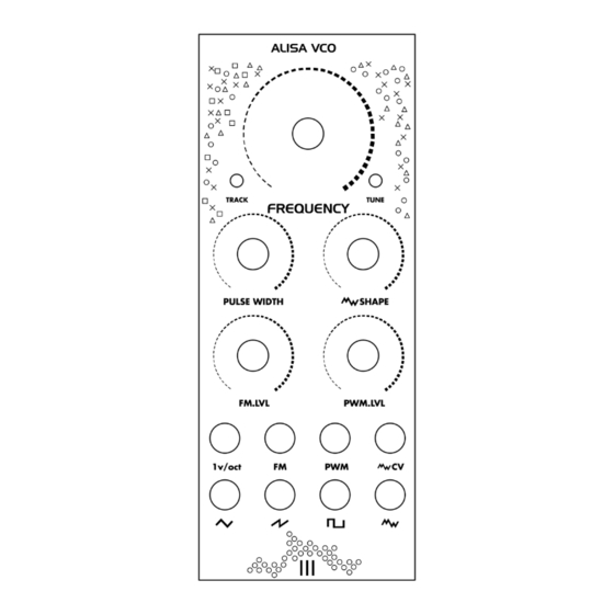
Always adhere to proper soldering techniques, work in a well-ventilated space, and handle electronic components with care to ensure the longevity and optimal performance of your Alisa VCO. Ensure you have all the necessary components listed in the Bill of Materials. - Page 3 Legend: Front:...
- Page 4 Back:...
-
Page 5: Assembly Guide
Assembly Guide: Step 1: Identify and Sort Components Organize the components into groups based on their types: resistors, capacitors, diodes, potentiometers, connectors, switches and jack sockets. Step 2: Diodes (Front) Insert and solder diodes according to the legend. 1N4148 are placed vertically. 1N4148 diodes For easier soldering, when diode... - Page 6 Step 6: Diodes (Back) Insert and solder 1N4002 diodes according to the legend. Ensure correct orientation, referring to the diode's polarity. Step 7: 10uf Capacitors (Back) Solder 10uf capacitors onto the designated positions on the PCB according to legend. Ensure correct orientation of capacitors, referring to the capacitors polarity. Step 8: Power Connector Solder the IDC connector (Power connector) into its designated spot.
- Page 7 Step 12: Calibration. Power off your Eurorack system. Connect the power cable, ensuring correct polarity. Power on your Eurorack system. Let the module warm up for at least 20 minutes. Turn the frequency knob all the way counter clockwise. Turn the HFT trimpot counter clockwise until you hear clicking from the trimpot.
-
Page 8: Additional Information
Additional Information: For any additional questions or support, please contact Tre Modular at support@tremodular.com Happy patching!
Need help?
Do you have a question about the Alisa VCO and is the answer not in the manual?
Questions and answers