Table of Contents
Advertisement
Available languages
Available languages
Quick Links
Manuale di istruzioni / Bedienungsanleitung /
Instructions Manual / Manuel d'instructions /
Manual de instrucciones / Handleiding
IT
PENTOLE
DE
KOCHKESSEL
EN
BOILING PANS
FR
MARMITES
ES
MARMITAS
NL
KOOKKETELS
ISTRUZIONI ORIGINALI / Übersetzung der Originalbetriebsanleitung / Translation of the original instructions / Traduction du instructions originales /
Traducción de las instrucciones originales / Vertaling van de originele instructies / Oversættelse af de originale anvisninger
Mareno Ali Group S.r.l.
Via Conti Agosti, 231/247
I-31010 Mareno di Piave (TV)
IT / CH
DE / AT / IT / BE / LU / CH
GB / IE / MT
FR / BE / LU / CH
ES
NL / BE
M1 70-90
DOC.NO
MACS0004050
Edition
001 2419
Advertisement
Chapters
Table of Contents

Related Manuals for Mareno M1 70-90

Summary of Contents for Mareno M1 70-90
- Page 1 ISTRUZIONI ORIGINALI / Übersetzung der Originalbetriebsanleitung / Translation of the original instructions / Traduction du instructions originales / Traducción de las instrucciones originales / Vertaling van de originele instructies / Oversættelse af de originale anvisninger Mareno Ali Group S.r.l. DOC.NO MACS0004050 Via Conti Agosti, 231/247 Edition 001 2419 I-31010 Mareno di Piave (TV)
- Page 2 ISTRUZIONI PER L’INSTALLAZIONE, USO E MANUTENZIONE Leggere attentamente il libretto e conservarlo con cura per tutta la durata del prodotto. Leggere le istruzioni prima dell’installazione e utilizzo dell’apparecchiatura! ANWEISUNGEN FÜR INSTALLATION, GEBRAUCH UND WARTUNG Die Bedienungsanleitung aufmerksam lesen und sorgfältig aufbewahren. Lesen Sie die Anweisungen vor der Installation und Inbetriebnahme des Gerätes! INSTRUCTIONS FOR INSTALLATION, OPERATION AND MAINTENANCE Read the manual thoroughly and keep it in a safe place throughout the product’s service life.
- Page 3 SCHEMA DI INSTALLAZIONE - INSTALLATION DIAGRAM - INSTALLATIONSPLAN - SCHÉMA D’INSTALLATION ESQUEMA DE INSTALACION - INSTALLATIESCHEMA...
- Page 4 SCHEMA DI INSTALLAZIONE - INSTALLATION DIAGRAM - INSTALLATIONSPLAN - SCHÉMA D’INSTALLATION ESQUEMA DE INSTALACION - INSTALLATIESCHEMA...
- Page 5 SCHEMA DI INSTALLAZIONE - INSTALLATION DIAGRAM - INSTALLATIONSPLAN - SCHÉMA D’INSTALLATION ESQUEMA DE INSTALACION - INSTALLATIESCHEMA...
- Page 6 SCHEMA DI INSTALLAZIONE - INSTALLATION DIAGRAM - INSTALLATIONSPLAN - SCHÉMA D’INSTALLATION ESQUEMA DE INSTALACION - INSTALLATIESCHEMA...
- Page 7 SCHEMA DI INSTALLAZIONE - INSTALLATION DIAGRAM - INSTALLATIONSPLAN - SCHÉMA D’INSTALLATION ESQUEMA DE INSTALACION - INSTALLATIESCHEMA...
- Page 8 SCHEMA DI INSTALLAZIONE - INSTALLATION DIAGRAM - INSTALLATIONSPLAN - SCHÉMA D’INSTALLATION ESQUEMA DE INSTALACION - INSTALLATIESCHEMA...
- Page 9 SCHEMA DI INSTALLAZIONE - INSTALLATION DIAGRAM - INSTALLATIONSPLAN - SCHÉMA D’INSTALLATION ESQUEMA DE INSTALACION - INSTALLATIESCHEMA...
- Page 10 SCHEMA DI INSTALLAZIONE - INSTALLATION DIAGRAM - INSTALLATIONSPLAN - SCHÉMA D’INSTALLATION ESQUEMA DE INSTALACION - INSTALLATIESCHEMA...
- Page 11 UNIONE APPARECCHIATURE - GERÄTEZUSAMMENSCHLUSS - COMBINING APPLIANCES - UNIÓN D'APPAREIL UNION DE VARIOS EQUIPOS - VERBINDING VAN APPARATEN Serie - Series - Série 700/900...
- Page 12 FIGURE - ABB. - FIG.
- Page 13 DATI TECNICI - TECHNICAL DATA - TECHNISCHE DATEN - CARACTERISTIQUES TECHNIQUES - DATOS TECNICOS - TECHNISCHE GEGEVENS Ugelli e regolazioni - Düsen und Einstellungen - Nozzles and settings Buses et les paramètres - Boquillas y los ajustes - Nozzles en instellingen MPE76GD5 MPE98GD10 MPE98GD15...
- Page 14 DATI TECNICI - TECHNICAL DATA - TECHNISCHE DATEN - CARACTERISTIQUES TECHNIQUES - DATOS TECNICOS - TECHNISCHE GEGEVENS T2.1 Categorie a pressioni - Kategorien e Druck - Categories and pressures - Catégories et pressions - Las categorías y las presiones - Categorieën en druk .PE..10.;...
- Page 15 DATI TECNICI - TECHNICAL DATA - TECHNISCHE DATEN - CARACTERISTIQUES TECHNIQUES - DATOS TECNICOS - TECHNISCHE GEGEVENS T2.2 Categorie a pressioni - Kategorien e Druck - Categories and pressures - Catégories et pressions - Las categorías y las presiones - Categorieën en druk .PE..5;...
- Page 16 DATI TECNICI - TECHNICAL DATA - TECHNISCHE DATEN - CARACTERISTIQUES TECHNIQUES - DATOS TECNICOS - TECHNISCHE GEGEVENS...
- Page 17 DATI TECNICI - TECHNICAL DATA - TECHNISCHE DATEN - CARACTERISTIQUES TECHNIQUES - DATOS TECNICOS - TECHNISCHE GEGEVENS...
-
Page 18: Table Of Contents
AVVERTENZE PER L'UTILIZZATORE............................. 17 DISPOSITIVI DI PROTEZIONE INDIVIDUALE ........................18 RISCHI RESIDUI ..................................19 INFORMAZIONI GENERALI ..............................20 DATI DELLA APPARECCHIATURA ........................... 20 AVVERTENZE GENERALI ............................20 AVVERTENZE PER L'INSTALLATORE ........................... 20 AVVERTENZE PER IL MANUTENTORE ..........................20 AVVERTENZE PER LA PULIZIA .............................. 20 DISPOSITIVI DI SICUREZZA E CONTROLLO ...................... -
Page 19: Avvertenze Per L'utilizzatore
• Non manomettere i componenti dell'appa- AVVERTENZE PER L'UTILIZZATORE recchiatura. • Leggere attentamente questo manuale. • Installare a monte di tutti gli apparecchi Fornisce importanti informazioni sulla si- funzionanti a gas liquido (G30 e/o G31), curezza di installazione, d'uso e manuten- un regolatore di arresto per sovrapressio- zione della apparecchiatura. -
Page 20: Dispositivi Di Protezione Individuale
DISPOSITIVI DI PROTEZIONE INDIVIDUALE cambio pagina Si riporta di seguito una tabella riassuntiva dei Dispositivi di Protezione Individuale (DPI) da utilizzare durante le varie fasi di vita dell'apparecchiatura. Indumenti Calzature Casco Protettori Guanti Occhiali Mascherina auricolari protezione sicurezza elmetto Fase Trasporto Movimentazione Disimballo... -
Page 21: Rischi Residui
RISCHI RESIDUI La macchina evidenzia rischi che non sono stati eliminati completamente dal punto di vista progettuale o con l'installazione di adeguate protezioni. Per la completa informazione del Cliente si riportano, di seguito, i rischi residui che permangono sulla macchina: tali comportamenti sono da considerare scorretti e quindi sono severamente vietati. -
Page 22: Informazioni Generali
INFORMAZIONI GENERALI • Installare a monte di tutti gli apparecchi funzionanti a gas li- quido (G30 e/o G31), un regolatore di arresto per sovrapres- In questo capitolo sono riportate le informazioni genera- sione (OPSO). li che devono essere a conoscenza di tutti gli utilizzatori di questo manuale. -
Page 23: Pentole Autoclave
MANOMETRO • L’installazione, la conversione ad altro tipo di gas e la ma- nutenzione dell’apparecchiatura devono essere effettuati da L' apparecchiatura è dotata di un manometro , collocato sul personale qualificato e autorizzato dal costruttore, in confor- pannello comandi , che indica il valore della pressione del va- mità... -
Page 24: Sistema Per Lo Scarico Dei Fumi
FISSAGGIO DELL'APPARECCHIATURA AL PAVIMENTO • Non usare tubazioni di allacciamento di diametro inferiore a quello della connessione gas della apparecchiatura. Fissare al pavimento l' apparecchiatura di larghezza 40 cm in- • Verificare , dopo l'allacciamento , la assenza di perdite nei stallata singolarmente. -
Page 25: Adattamento Ad Un Altro Tipo Di Gas
ISTRUZIONI PER L'USO sione se la pressione di alimentazione è superiore a quella massima indicata. • L’apparecchio è destinato ad essere collegato in modo per- AVVERTENZE PER L'UTILIZZATORE manente alla rete idrica e non tramite un set di giunzioni se- parabile. -
Page 26: Pentola Diretta Gas
• Eseguire la pulizia secondo le istruzioni sitivo termico di interruzione, il presente ap- fornite nel capitolo "ISTRUZIONI PER LA parecchio non deve essere alimentato con PULIZIA". un apparecchio di manovra esterno, quale • Non tenere materiali infiammabili in pros- un temporizzatore oppure essere connes- simità... -
Page 27: Pentola Indiretta Gas
ACCENSIONE E SPEGNIMENTO BRUCIATORI Quando la posizione di cottura prescelta e' diversa da "5" il riscaldamento procede in modo intermittente. Si attiva e disat- La manopola di comando della valvola gas ha le seguenti po- tiva in modo automatico. La intensita' della ebollizione dell'ac- sizioni di utilizzo : qua puo' variare visivamente , senza alcun effetto sulla cottura. -
Page 28: Pentola Diretta Elettrica
0 Spento Spento Potenza minima - Mantenimento (BIANCO) Ingresso acqua calda/fredda 2..4 Potenze intermedie - Cottura 1 Attivazione alimentazione elettrica Potenza massima • Aprire il coperchio. • Ruotare verso destra la impugnatura del rubinettone frontale Accensione di scarico. Il rubinettone e' completamente chiuso solo quan- Ruotare la manopola del regolatore di energia in qualsiasi po- do la impugnatura e' in posizione verticale. -
Page 29: Pentola Indiretta Elettrica
• Ruotare verso destra la impugnatura del rubinettone frontale • Utilizzare sale di pezzatura minuta da introdurre nella vasca di scarico. Il rubinettone e' completamente chiuso solo quan- quando l' acqua e' in ebollizione. Non introdurre nella vasca do la impugnatura e' in posizione verticale. sale da cucina di grossa pezzatura. -
Page 30: Periodi Di Inutilizzo
• Riempire la vasca fino a raggiungere la tacca di livello mas- • Far funzionare le apparecchiature elettriche alla minima tem- simo presente sulla parete della vasca. Non utilizzare l'ap- peratura per almeno 60 minuti. parecchiatura con un livello d'acqua superiore alla tacca di ISTRUZIONI PER LA PULIZIA livello massimo. -
Page 31: Adattamento Ad Un Altro Tipo Di Gas
mità alle normative di sicurezza in vigore e alle istruzioni di • la regolarita' di accensione delle resistenze di riscaldamento. questo manuale. 15 RISOLUZIONE MALFUNZIONAMENTI • Individuare il modello della apparecchiatura. Il modello è ri- portato sull'imballo e sulla targa dati dell'apparecchiatura. PENTOLA DIRETTA GAS •... -
Page 32: Pentola Diretta Elettrica
• La conduttura o l' ugello sono ostruiti. PENTOLA INDIRETTA GAS • Il rubinetto gas o la valvola gas e' guasta. • Il bruciatore e' guasto ( fori uscita gas intasati ). Sostituzione della valvola gas, del bruciatore, del pilota, •... -
Page 33: Pulizia Delle Parti Interne
Sostituzione del termostato • Smontare il pannello frontale. • Smontare e sostituire il componente. • Rimontare tutte le parti. Seguire, in ordine inverso, la sequen- za utilizzata per il loro smontaggio. Sostituzione della resistenza di livello e resistenza riscal- dante •... - Page 35 HINWEISE FÜR DEN BENUTZER ............................2 PERSÖNLICHE SCHUTZAUSRÜSTUNGEN .......................... 3 RESTRISIKEN..................................4 ALLGEMEINE INFORMATIONEN ............................5 GERÄTEDATEN ................................ 5 ALLGEMEINE HINWEISE ............................5 HINWEISE FÜR DEN INSTALLATIONSTECHNIKER ......................5 HINWEISE FÜR DEN WARTUNGSTECHNIKER ........................5 REINIGUNGSHINWEISE ................................. 5 SICHERHEITS- UND REGELVORRICHTUNGEN ....................5 DIREKT BEHEIZTE KOCHKESSEL............................
-
Page 36: Hinweise Für Den Benutzer
• Verdecken Sie die am Gerät vorhandenen HINWEISE FÜR DEN BENUTZER Belüftungsschlitze und Auslassöffnungen • Lesen Sie diese Anleitung aufmerksam nicht. durch. Sie enthält wichtige Hinweise zur • Nehmen Sie keine unerlaubten Änderun- Installations-, Gebrauchs- und Wartungs- gen an den Geräteteilen vor. sicherheit des Geräts. -
Page 37: Persönliche Schutzausrüstungen
PERSÖNLICHE SCHUTZAUSRÜSTUNGEN cambio pagina Die folgende Tabelle gibt einen Überblick über die Persönlichen Schutzausrüstungen (PSA), die während der verschiedenen Lebensphasen des Geräts zu verwenden sind. Schutzkleidung Sicherheitsschuhe Handschuhe Augenschutz Gehörschutz Atemschutz Kopfschutz Phase Transport Handling Auspacken Montage Normaler Gebrauch X (*) Einstellungen Normale Reinigung Außerordentliche... -
Page 38: Restrisiken
RESTRISIKEN Restrisiken, die bei der Entwicklung nicht vollständig vermieden oder durch geeignete Schutzvorrichtungen beseitigt werden konnten, werden auf der Maschine gekennzeichnet. Zur Information des Kunden werden im Folgenden die verbleibenden Restrisiken der Maschine aufgeführt: Diese Verhaltensweisen sind unzulässig und damit streng verboten. RESTRISIKEN GEFÄHRLICHE SITUATION WARNUNG... -
Page 39: Allgemeine Informationen
ALLGEMEINE INFORMATIONEN • Vor allen mit Flüssiggas (G30 und/oder G31) betriebenen Geräten muss eine Überdrucksicherung (OPSO) installiert Dieses Kapitel enthält die allgemeinen Informationen, die werden. sämtlichen Benutzern dieser Anleitung bekannt sein müssen. Die spezifischen Informationen für die einzelnen Benutzer die- REINIGUNGSHINWEISE ser Anleitung sind in den folgenden Kapiteln enthalten („AN- •... -
Page 40: Druckkochkessel
MANOMETER • Lesen Sie diese Anleitung aufmerksam durch. Sie enthält wichtige Hinweise zur Installations-, Gebrauchs- und War- Das Gerät ist mit einem Manometer ausgestattet, das sich am tungssicherheit des Geräts. Bedienfeld befindet und den Druckwert des im Zwischenraum • Installation, Umstellung auf eine andere Gasart und War- enthaltenen Dampfes anzeigt. -
Page 41: Wrasenabzugssystem
• Halten Sie einen Mindestabstand von 10 cm von den angren- 11 ANSCHLÜSSE zenden Wänden ein. Falls das Gerät sehr nahe an Wänden, Position und Abmessungen der Anschlüsse sind dem Installa- Trennwänden, Küchenmöbeln, Dekorelementen, usw. aufge- tionsplan am Anfang dieser Anleitung zu entnehmen. stellt werden muss, dürfen diese in nicht brennbarem Mate- rial ausgeführt sein. -
Page 42: Umstellung Auf Eine Andere Gasart
• Dieses Symbol zeigt an, dass das Gerät in ein Potentia- • Lockern Sie die Schraube V. lausgleichsystem eingebunden und gemäß den geltenden • Bauen Sie die Düse UM aus und ersetzen Sie sie durch die Vorschriften angeschlossen werden muss. mit der in Tabelle T1 angegebenen Düse. -
Page 43: Direkt Beheizter Gas-Kochkessel
• Das Gerät dient zum Garen von Lebensmit- ien usw. bestimmt. Er ist jedoch nicht für teln gemäß den Gebrauchshinweisen. Je- die kontinuierliche Speisenproduktion in großen Mengen bestimmt. ACHTUNG: der davon abweichende Gebrauch gilt als Das Öffnen des Ablassventils bewirkt zweckwidrig. -
Page 44: Indirekt Beheizter Gas-Kochkessel
• Nehmen Sie am Ende des Arbeitstags eine gründliche Reini- Zum Ausschalten des Zündbrenners den Knebel drücken und gung des Beckens vor, damit sich keine korrosiven Ablage- auf " " drehen. rungen darin bilden können. EIN- UND AUSSCHALTEN DER BEHEIZUNG BECKEN FÜLLEN UND ENTLEEREN Der Schaltknebel des Energiereglers hat folgende Betriebs- Füllen... - Page 45 Einschalten des Zündbrenners • Nehmen Sie am Ende des Arbeitstags eine gründliche Reini- gung des Beckens vor, damit sich keine korrosiven Ablage- Sicherstellen, dass der Schaltknebel des Wahlschalters auf "1" rungen darin bilden können. steht. MANUELLE FÜLLEN DES ZWISCHENRAUMS Knebel drücken und auf " "...
-
Page 46: Direkt Beheizter Elektro-Kochkessel
DIREKT BEHEIZTER ELEKTRO-KOCHKESSEL • Die gelbe Kontrolllampe erlischt. GAREN BEDIENUNGSHINWEISE • Füllen Sie das Becken. • Das Gerät ist zum Garen oder Zubereitung von Speisen in • Regeln Sie den Heizbetrieb je nach Garbedarf. Wasser bestimmt. Bei Wahl einer anderen Garposition als "5" ist der Heizbetrieb •... -
Page 47: Stillstandzeiten
BECKEN FÜLLEN UND ENTLEEREN NACH DER ARBEITSSCHICHT • Schalten Sie die Beheizung aus. Füllen mit Wasserhahn • Entleeren Sie das Becken vollständig. • Drehen Sie den Knebel des Wahlschalters auf "0". • Den Wasserhahn (Drehknopf an der Bedienblende) öffnen und das Becken bis zur Markierung füllen. 14 STILLSTANDZEITEN Füllen Gehen Sie vor einem geplanten Stillstand des Gerätes wie... -
Page 48: Wartungsanweisungen
WRASENVENTIL AN DEN KOCHKESSELN MIT DRUCKDE- GASGERÄTE CKEL Setzen Sie das Gerät entsprechend den Gebrauchsanleitun- • Reinigen Sie die Vorrichtung regelmäßig mit Wasser und gen und -hinweisen im Kapitel „GEBRAUCHSANLEITUNGEN“ gewöhnlichen Flüssigreinigern. Anschließend nachspülen in Betrieb und kontrollieren Sie: und trocknen. •... -
Page 49: Indirekt Beheizter Gas-Kochkessel
Die Heizleistung lässt sich nicht regulieren. • Der Energieregler ist defekt. Mögliche Ursachen: 16 ERSATZ VON BAUTEILEN • Der Energieregler ist defekt. HINWEISE FÜR DEN ERSATZ VON BAUTEILEN. INDIREKT BEHEIZTER GAS-KOCHKESSEL • Bei Elektrogeräten vor jedem Eingriff unbedingt den Netzste- cker ziehen, sofern vorhanden. -
Page 50: Direkt Beheizter Elektro-Kochkessel
DIREKT BEHEIZTER ELEKTRO-KOCHKESSEL • Zündbrenner • Thermoelement • Zündkerze Ersatz des Heizelements • Magnetventil für Wasserzulauf • Nehmen Sie die Frontblende ab. • Energieregler • Das Teil ausbauen und ersetzen. • Kontrolllampe. • Sämtliche Teile wieder einbauen. In umgekehrter Reihenfol- •... - Page 51 REMINDERS FOR THE USER ..............................2 PERSONAL PROTECTIVE EQUIPMENT ..........................3 RESIDUAL RISKS ..................................4 GENERAL INFORMATION ............................... 5 APPLIANCE SPECIFICATIONS ..........................5 GENERAL PRESCRIPTIONS ............................ 5 REMINDERS FOR THE INSTALLER ............................5 REMINDERS FOR THE MAINTENANCE TECHNICIAN ......................5 REMINDERS FOR CLEANING ..............................
-
Page 52: Reminders For The User
a gas pressure regulator to stop potential REMINDERS FOR THE USER gas overpressures is required (OPSO). • Read this manual carefully. It provides im- • Close doors and drawers after use. portant information for safe installation, N.B.: To ensure correct hygiene and redu- use and maintenance of the appliance. -
Page 53: Personal Protective Equipment
PERSONAL PROTECTIVE EQUIPMENT cambio pagina Given below is a summary table of the Personal Protective Equipment (PPE) to be used during the service life of the equipment. Protective Safety Gloves Goggles Mask Helmet garments footwear protectors Phase Transport Handling Unpacking Assembly Normal use X (*) -
Page 54: Residual Risks
RESIDUAL RISKS There are risks on the machine that have not been completely eliminated from a design standpoint or with the installation of adequate protection devices. To provide the Customer with full information, given below are the residual risks that remain on the machine: such actions are deemed improper and therefore strictly forbidden. -
Page 55: General Information
GENERAL INFORMATION • Do not use corrosive products when cleaning the floor or the base underneath the appliance. This chapter contains general information which all users of the • Do not wash the body or flame spreader of the hob burners manual must be familiar with. -
Page 56: Autoclave Pans
AUTOCLAVE PANS 7 HANDLING The packaging is marked with warning symbols that indicate STEAM DISCHARGE VALVE the precautions to be taken when handling the appliance to avoid damage. The appliance must only be handledusing su- The appliance is equipped with an automatic valve, built into itable equipment. -
Page 57: Connections
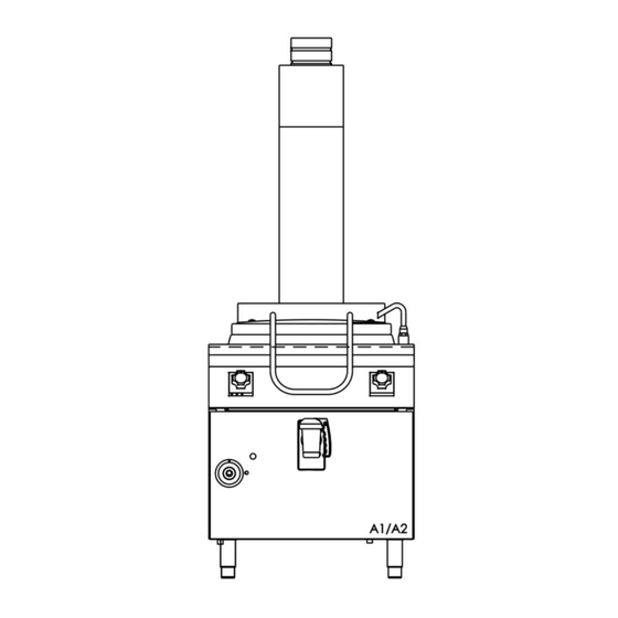
APPLIANCE TYPE "A1" PROTECTIVE EARTH AND EARTH BONDING CONNEC- TIONS • Position the "A1" type appliance below an extractor hood to ensure smoke and fumes generated by cooking are removed. Connect the appliance to an efficient earth circuit. Connect the earth conductor to the terminal with the symbol located APPLIANCE TYPE "B21"... -
Page 58: Commissioning
use. Any other use is considered to be im- REPLACING THE MAIN BURNER NOZZLE AND ADJU- STING THE PRIMARY AIR FLOW. proper. • Remove the front panel. • Do not allow the appliance to operate emp- • Slacken screw V. •... -
Page 59: Direct Heat Gas Boiling Pan
WARNING!: Opening the drain valve will BURNER IGNITION AND EXTINCTION The gas valve control knob has the following positions cause the hot pan content to escape. ATTENTION!: In order to avoid dangers due Pilot ignition to the accidental reset of the disconnection thermal device, this appliance must not be Maximum flame powered using an external operating devi-... -
Page 60: Indirect Heat Gas Boiling Pan
AT THE END OF SERVICE • Fill the well until the water is level with the maximum level in- dicated on the wall of the well. Do not use the appliance with • Switch the heating off. the water level above the maximum indicated level. •... -
Page 61: Direct Heat Electric Boiling Pan
Switching on • Light the burners. • Adjust the heating according to your cooking requirements. Turn the energy regulator knob to any position between "1" and When the chosen cooking position is other than "5", heating "5". is intermittent. It switches on and off automatically. The boiling •... -
Page 62: Prolonged Disuse
FILLING THE JACKET AT THE END OF SERVICE With the selector knob in any position other than 'off', the jacket • Switch the heating off. is automatically loaded. • Empty the well completely. • Turn the knob to position "0". FILLING AND EMPTYING THE WELL 14 PROLONGED DISUSE Before any prolonged disuse of the appliance, proceed as fol-... -
Page 63: Instructions For Maintenance
INSTRUCTIONS FOR MAINTENANCE ELECTRICAL APPLIANCES Switch on the appliance as directed in the instructions and re- REMINDERS FOR THE MAINTENANCE TECHNICIAN minders for use given in Chapter " INSTRUCTIONS FOR USE " and check: The manufacturer will not be liable for any damage or in- jury resulting from failure to observe the following rules. -
Page 64: Direct Heat Electric Boiling Pan
• Defective burner ( gas outlet holes clogged ). • Re-assemble all parts. For assembly, proceed in reverse or- • Defective pressure switch. der. • Defective energy regulator. Replacing the energy regulator, the knob and the indicator Heating cannot be adjusted light Possible causes: •... -
Page 65: Cleaning The Interior
Replacing the level resistor and the heating element • Empty the jacket. • Remove the front panel. • Remove the thermostat bulb from its seat. • Remove and replace the component. • Re-assemble all parts. For assembly, proceed in reverse or- der. - Page 67 AVERTISSEMENTS POUR L’UTILISATEUR ........................... 2 DISPOSITIFS DE SÉCURITÉ INDIVIDUELS .......................... 3 RISQUES RÉSIDUELS ................................4 INFORMATIONS GÉNÉRALES ............................... 5 CARACTÉRISTIQUES DE L'APPAREIL ........................5 AVERTISSEMENTS GÉNÉRAUX ..........................5 AVERTISSEMENTS POUR L’INSTALLATEUR ........................5 AVERTISSEMENTS POUR LE TECHNICIEN PRÉPOSÉ À L'ENTRETIEN ................5 AVERTISSEMENTS POUR LE NETTOYAGE .........................
-
Page 68: Avertissements Pour L'utilisateur
• Ne pas obstruer les bouches d’aération et AVERTISSEMENTS POUR L’UTILISATEUR d’évacuation de l’appareil. • Lire ce manuel attentivement. Il donne des • Ne pas modifier les composants de l’ap- informations importantes pour l’installa- pareil. tion, l’utilisation et l’entretien de l’appareil •... -
Page 69: Dispositifs De Sécurité Individuels
DISPOSITIFS DE SÉCURITÉ INDIVIDUELS cambio pagina Le tableau ci-dessous récapitule les dispositifs de protection individuels (DPI) à porter pendant toutes les interventions sur l'appareil. Vêtement Chaussures Protections Gants Lunettes Masque Casque auditives protection sécurité Phase Transport Manutention Déballage Montage Utilisation ordinaire X (*) Réglages Nettoyage ordinaire... -
Page 70: Risques Résiduels
RISQUES RÉSIDUELS La machine signale les risques qui n'ont pas été entièrement éliminés en phase de projet ou par l'installation de protections spécifiques. Pour une bonne information des clients, nous indiquons ci-dessous les risques résiduels qui existent sur la machine : il s'agit de comportements incorrects qui sont strictement interdits. -
Page 71: Informations Générales
INFORMATIONS GÉNÉRALES • Installer en amont de tous les appareils à gaz liquide (G30 et/ ou G31) un régulateur de pression (OPSO). Ce chapitre donne des informations générales dont les utili- sateurs de ce manuel doivent prendre connaissance. Les in- AVERTISSEMENTS POUR LE NETTOYAGE formations spécifiques destinées aux différents utilisateurs •... -
Page 72: Casseroles Autocuiseurs
MANOMÈTRE • L'installation, la conversion à un autre type de gaz et l'entre- tien de l'appareil doivent être effectués par des installateurs Un manomètre situé sur le panneau de commandes, qui in- qualifiés et agréés par le fabricant, conformément aux nor- dique la valeur de la pression de la vapeur dans la chemise mes de sécurité... -
Page 73: Système D'évacuation Des Fumées
UNION DE PLUSIEURS APPAREILS Le symbole signifie : 1. Retirer les micro-joints sur la paroi latérale. 2. Arrière: retirer la vis à tête fraisée M5X12. Insérer le sup- ATTENTION ! TENSION DANGEREUSE. port de connexion latéralement et resserrer la vis. Avant: •... -
Page 74: Adaptation À Un Autre Type De Gaz
dant toute la durée de vie utile de l'appa- soupape automatic en appuyant sur le bouton noir; contrôler également que le trou d'évacuation de la vapeur soit ouvert. reil. Pression de service de la soupape: 5kPa (0,05bar). • L'installation, la conversion à un autre type de gaz et l'entretien de l'appareil doi- 12 ADAPTATION À... -
Page 75: Casserole Directe Gaz
• Il est conseillé de porter des équipements CASSEROLE DIRECTE GAZ personnels de protection ; risque de ren- AVERTISSEMENT versement d'aliments très chauds. • Cet appareil est destiné à la cuisson ou à la préparation d'a- • Pendant le fonctionnement de l'appareil, liments à... -
Page 76: Casserole Indirecte Gaz
• La veilleuse peut être observée à travers l'orifice d'inspection • Lorsque le chauffage est en marche, il faut maintenir dans la se trouvant sur le panneau avant. cuve un niveau d'eau proche du repère maximum se trouvant sur la paroi de la cuve. Allumage du brûleur principal •... -
Page 77: Casserole Directe Électrique
Vidange CUISSON Soulever et tourner à gauche la poignée du robinet de vidange • Remplir la cuve. avant. Lorsque le robinet est ouvert, la poignée reste en posi- • Allumer les brûleurs. tion horizontale. • Régler le chauffage selon les besoins de cuisson. Lorsque la position de cuisson choisie diffère de "5", le chauf- fage marche de façon intermittente. -
Page 78: Casserole Indirecte Électrique
2..4 Puissances intermédiaires - Cuisson • Ouvrir le robinet de niveau " L ". • Verser l'eau déminéralisée dans le trou d'alimentation. Puissance maximum • Cesser de verser lorsque l'eau commence à sortir du robinet de niveau " L ". •... -
Page 79: 14 Périodes D'inactivité
Extinction • Ne pas utiliser de produits chimiques contenant du chlore. • Ne pas utiliser d'objet pointu qui pourrait rayer ou détériorer Tourner la manette du régulateur d'énergie en position " ". les surfaces. • Le voyant jaune s'éteint. CUVES DE CUISSON CUISSON •... -
Page 80: 15 Résolution Des Pannes
Ajouter à l'eau l'inhibiteur de corrosion (phosphate trisodique) • Le régulateur d'énergie est défectueux. conformément aux instructions données par son fabricant. Le chauffage ne se règle pas. Causes possibles : APPAREIL À GAZ Mettre l'appareil en marche en respectant les consignes et •... -
Page 81: Remplacement De Pièces
• Le régulateur d'énergie est défectueux. CASSEROLE DIRECTE ÉLECTRIQUE 16 REMPLACEMENT DE PIÈCES Remplacement de la résistance chauffante • Démonter le panneau avant AVERTISSEMENTS POUR LE REMPLACEMENT DE • Déposer et remplacer le composant. PIÈCES. • Remonter toutes les pièces. Exécuter les opérations de •... -
Page 82: Casserole Directe Électrique
• Brûleur principal • Veilleuse • Thermocouple • Bougie d'allumage • Électrovanne d'alimentation d'eau • Régulateur d'énergie • Voyant. • Sélecteur • Pressostat • Résistance de niveau CASSEROLE DIRECTE ÉLECTRIQUE • Électrovanne d'alimentation d'eau • Régulateur d'énergie • Voyant. • Sélecteur •... - Page 83 ADVERTENCIAS PARA EL USUARIO ............................. 2 EQUIPOS DE PROTECCIÓN INDIVIDUAL ..........................3 RIESGOS RESIDUALES ................................. 4 INFORMACIÓN GENERAL ..............................5 DATOS DEL EQUIPO ..............................5 ADVERTENCIAS GENERALES ..........................5 ADVERTENCIAS PARA EL INSTALADOR ..........................5 ADVERTENCIAS PARA EL MANTENEDOR ........................... 5 ADVERTENCIAS PARA LA LIMPIEZA .............................
-
Page 84: Advertencias Para El Usuario
• Instale un regulador de parada por sobre- ADVERTENCIAS PARA EL USUARIO presión (OPSO) antes de todos los apa- • Leer atentamente este manual. Sumini- ratos que funcionan con gas licuado (G30 stra información importante sobre la segu- y/o G31). ridad de instalación, uso y mantenimiento •... -
Page 85: Equipos De Protección Individual
EQUIPOS DE PROTECCIÓN INDIVIDUAL cambio pagina A continuación aparece una tabla de recapitulación de los Equipos de Protección Personal (EPP) que se deben utilizar durante las distintas fases de vida de los aparatos. Equipo Calzado Protectores Guantes Gafas Máscara Casco auriculares protección seguridad... -
Page 86: Riesgos Residuales
RIESGOS RESIDUALES La máquina presenta riesgos que no han sido eliminados completamente con el proyecto o con la instalación de protecciones. Para la información completa del cliente, a continuación se indican los riesgos residuales existentes en la máquina: las situaciones peligrosas se crean con comportamientos incorrectos que están terminantemente prohibidos. RIESGO RESIDUAL SITUACIÓN PELIGROSA ADVERTENCIA... -
Page 87: Información General
INFORMACIÓN GENERAL • Instale un regulador de parada por sobrepresión (OPSO) antes de todos los aparatos que funcionan con gas licuado En este capítulo se suministran informaciones generales que (G30 y/o G31). deben conocer todos los usuarios de este manual. Las infor- maciones específicas para cada usuario del manual figuran en ADVERTENCIAS PARA LA LIMPIEZA los capítulos siguientes ("INSTRUCCIONES PARA ... -
Page 88: Ollas Autoclave
MANÓMETRO normas de seguridad vigentes y con las instrucciones dadas en este manual. El equipo está dotado de un manómetro, situado en el tablero • Observar de qué modelo es el equipo. El modelo está indica- de mandos, que indica la presión del vapor contenido en la do en el embalaje y en la placa de datos del equipo. -
Page 89: Sistema De Salida De Humos
UNIÓN DE VARIOS EQUIPOS CONEXIÓN A LA RED ELÉCTRICA Retire las microjuntas del flanco. Controlar si el equipo está preparado para funcionar con la Parte trasera: retire el tornillo avellanado M5X12. Inser- tensión y frecuencia de la red local. Leer estos valores en la te el soporte de conexión lateralmente y vuelva a apretar placa de datos del equipo. -
Page 90: Adaptación A Otro Tipo De Gas
daños resultantes de la inobservancia CONEXIÓN AL DESAGÜE Los conductos de desagüe se han de realizar con materiales de las obligaciones indicadas a conti- resistentes a una temperatura de 100 °C. El fondo del equipo nuación. no ha de quedar expuesto al vapor producido por el vaciado del agua caliente. -
Page 91: Olla Directa De Gas
• No alterar de ningún modo los componen- más detalles consultar la hoja incluida en la tes del equipo. dotación). • Instale un regulador de parada por sobre- OLLA DIRECTA DE GAS presión (OPSO) antes de todos los apa- ratos que funcionan con gas licuado (G30 ADVERTENCIAS DE USO y/o G31). -
Page 92: Olla Indirecta De Gas
• Mantener presionado el mando alrededor de 20 segundos y • Cuando el calentamiento está activado, el agua se debe soltarlo. Si el piloto se apaga, repetir la operación. mantener cerca del nivel máximo indicado en la pared de la •... -
Page 93: Olla Directa Eléctrica
ENCENDIDO Y APAGADO DE LOS QUEMADORES AL FINAL DEL SERVICIO El mando de la válvula del gas tiene las siguientes posiciones: • Apagar el calentamiento. • Apagar los quemadores. Apagado • Vaciar la cuba por completo. • Girar el mando del selector a la posición "0". Encendido del piloto OLLA DIRECTA ELÉCTRICA Llama máxima... -
Page 94: Olla Indirecta Eléctrica
Apagado LLENADO Y VACIADO DE LA CUBA Girar el mando del regulador de energía a la posición " ". Llenado con grifo • El testigo amarillo se apaga. • Abrir el grifo de carga de agua (mando en el tablero) y llenar la cuba hasta la marca de referencia en relieve. -
Page 95: Períodos De Inactividad
• Vaciar la cuba por completo. • Presión de actuación de la válvula: 5 kPa (0,05 bar). • Girar el mando del selector a la posición "0". INSTRUCCIONES DE MANTENIMIENTO 14 PERÍODOS DE INACTIVIDAD ADVERTENCIAS PARA EL MANTENEDOR Antes de un período de inactividad del equipo, efectuar las operaciones que se describen a continuación: El fabricante del aparato no se puede considerar respon- sable de eventuales daños resultantes de la inobservancia... -
Page 96: Solución De Problemas
¡ATENCIÓN! Si la presión de alimentación del gas no está • La presión de alimentación del gas es insuficiente. entre los valores límite (mín. máx.) indicados en la tabla T2, • La llave o la válvula del gas están averiadas. apagar el equipo y consultar con la empresa suministradora •... -
Page 97: Olla Indirecta De Gas
• Volver a montar todas las partes. Efectuar las operaciones • Desmontar el panel de mandos. de desmontaje en orden contrario. • Desmontar y sustituir el componente. • Volver a montar todas las partes. Efectuar las operaciones Sustitución de regulador de energía, selector y testigo de desmontaje en orden contrario. - Page 99 AANWIJZINGEN VOOR DE GEBRUIKER ..........................2 PERSOONLIJKE BESCHERMINGSMIDDELEN ........................3 OVERBLIJVENDE RISICO'S ..............................4 ALGEMENE INFORMATIE ............................... 5 GEGEVENS VAN HET APPARAAT ........................... 5 ALGEMENE AANWIJZINGEN ........................... 5 AANWIJZINGEN VOOR DE INSTALLATEUR ......................... 5 AANWIJZINGEN VOOR DE ONDERHOUDSMONTEUR ......................5 AANWIJZINGEN VOOR DE REINIGING ..........................
-
Page 100: Aanwijzingen Voor De Gebruiker
• Dek de luchtinlaat- en uitlaatopeningen AANWIJZINGEN VOOR DE GEBRUIKER van het apparaat niet af. • Lees deze handleiding aandachtig door. • Maak de onderdelen van het apparaat niet Hierin vindt u belangrijke informatie over onklaar. de veiligheid bij de installatie, het gebruik •... -
Page 101: Persoonlijke Beschermingsmiddelen
PERSOONLIJKE BESCHERMINGSMIDDELEN cambio pagina Hieronder vindt u een overzichtstabel van de Persoonlijke Beschermingsmiddelen (PBM) die tijdens de verschillende levensfasen van het apparaat moeten worden gebruikt. Beschermende Veiligheids- Gehoorbescher Handschoenen Veiligheidsbril Gelaatsmasker Helm kleding schoenen mers Fase Transport Verplaatsing Uitpakken Montage Normaal gebruik X (*) Afstellingen... -
Page 102: Overblijvende Risico's
OVERBLIJVENDE RISICO'S De machine vertoont risico’s die niet volledig zijn weggenomen door het ontwerp of door de installatie van geschikte beschermingen. Om de klant volledig te informeren worden hieronder de restrisico’s vermeld die op de machine blijven bestaan: een dergelijk gedrag is niet correct en is dus streng verboden. RESTRISICO GEVAARLIJKE SITUATIE WAARSCHUWING... -
Page 103: Algemene Informatie
ALGEMENE INFORMATIE • Monteer vóór alle toestellen op vloeibaar gas (G30 en/of G31) een drukregelaar met overdrukafslagbeveiliging (OPSO). In dit hoofdstuk wordt de algemene informatie gegeven waar- van alle gebruikers van deze handleiding kennis moeten ne- AANWIJZINGEN VOOR DE REINIGING men. -
Page 104: Autoclaafketels
MANOMETER gekwalificeerd personeel dat hiertoe geautoriseerd is door de fabrikant, in overeenstemming met de geldende veili- Het apparaat heeft op het bedieningspaneel een manometer gheidsvoorschriften en de instructies in deze handleiding. die de waarde van de stoomdruk in de mantel aangeeft. •... -
Page 105: Dampafvoersysteem
BEVESTIGING VAN HET APPARAAT AAN DE VLOER • Gebruik geen aansluitleidingen met een kleinere diameter dan die van de gasaansluiting van het apparaat. Zet afzonderlijk geïnstalleerde apparaten met een breedte van • Controleer na de aansluiting of er geen lekken zijn op de ver- 40 cm vast aan de vloer. -
Page 106: Aanpassing Aan Een Ander Type Gas
• De voedingsdruk van het water moet tussen 150 kPa en 1000 13 INBEDRIJFSTELLING kPa liggen. Gebruik een drukverlager als de voedingsdruk Zie het hoofdstuk 'ONDERHOUDSINSTRUCTIES'. hoger is dan de aangegeven maximumdruk. • Het apparaat is bedoeld om permanent op de waterleiding GEBRUIKSAANWIJZING te worden aangesloten en niet met een scheidbare verbin- dingsset. -
Page 107: Direct Verhitte Gasketel
dichtgedraaid en/of moet de hoofdscha- LET OP!: Om elk gevaar door per ongeluk kelaar van de elektrische voeding, die bo- resetten van de thermische onderbreker te venstrooms van het apparaat geplaatst is, voorkomen, mag dit apparaat niet van stro- worden uitgeschakeld. om voorzien worden met een extern scha- •... -
Page 108: Indirect Verhitte Gasketel
ONTSTEKEN EN UITZETTEN VAN DE BRANDERS activeerd en gedeactiveerd. De intensiteit waarmee het water kookt kan op het oog variëren, zonder dat dit gevolgen heeft De bedieningsknop van de gasklep kan in de volgende stan- voor de bereiding. Wanneer de verhitting gedeactiveerd wordt, den worden gebruikt: gaat het gele controlelampje uit. -
Page 109: Direct Verhitte Elektrische Ketel
Aanzetten • Open het deksel. • Draai de handgreep van de aftapkraan aan de voorkant naar Draai de knop van de energieregelaar in een willekeurige stand rechts. De kraan is pas helemaal dicht als de handgreep in tussen “1” en “5”. verticale stand staat. -
Page 110: Elektrische, Indirect Verhitte Ketel
Legen • moet het bedieningspaneel (frontaal paneel voor de direct verhitte pannen en de braadpannen) worden verwijderd en Til de handgreep van de aftapkraan aan de voorkant op en moet de resetknop van de thermostaat worden ingedrukt. Dit draai hem naar links. Wanneer de kraan open is, blijft de mag uitsluitend worden gedaan door een gekwalificeerd en handgreep in horizontale positie. -
Page 111: Perioden Waarin Het Apparaat Niet Wordt Gebruikt
5 Hoogste vermogen garanderen en slijtage en defecten van de kraan te verminde- ren. (Zie voor meer informatie het bijgevoegde blad). Aanzetten GESATINEERDE OPPERVLAKKEN VAN ROESTVRIJ STA- Draai de knop van de energieregelaar in een willekeurige stand tussen “1” en “5”. •... -
Page 112: Inbedrijfstelling
INBEDRIJFSTELLING • Het thermokoppel is niet goed verbonden met de kraan of de gasklep. Na de installatie, aanpassing aan een ander gastype of on- • De knop van de kraan of de gasklep wordt onvoldoende in- derhoudswerkzaamheden moet de werking van het apparaat gedrukt. -
Page 113: Elektrische, Indirect Verhitte Ketel
• De energieregelaar is defect. • Monteer alle onderdelen weer. Doe dit door de werkzaamhe- den voor de demontage omgekeerd uit te voeren. ELEKTRISCHE, INDIRECT VERHITTE KETEL Vervanging van de thermostaat Het apparaat wordt niet warm. • Demonteer het frontpaneel. •... -
Page 114: Belangrijkste Onderdelen
18 BELANGRIJKSTE ONDERDELEN DIRECT VERHITTE GASKETEL • Gasklep • Hoofdbrander • Waakvlambrander • Thermokoppel • Ontstekingsbougie • Elektromagnetische watervulklep • Energieregelaar • Controlelampje. • Keuzeschakelaar • Veiligheidsthermostaat INDIRECT VERHITTE GASKETEL • Gasklep • Hoofdbrander • Waakvlambrander • Thermokoppel • Ontstekingsbougie •...
Need help?
Do you have a question about the M1 70-90 and is the answer not in the manual?
Questions and answers