
Related Manuals for RVE HUB

Summary of Contents for RVE HUB
- Page 1 Installation Manual GENERATION 1 For questions, contact us by phone at 450-902-1355, toll free 1-833-717-1355, rve.ca or by email at the address support@rve.ca.
-
Page 2: Safety Information
Improper use of the HUB may result in serious injury or death. For vertical installation on a wall, please refer to the indica- tions on the enclosure for the choice of orientation. -
Page 3: After Sales Service
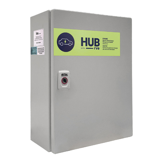
Please ensure that you have received the correct model of or replace, at its factory or on site, according to its choice, HUB you ordered; refer to your order. If you receive a damaged any merchandise which, upon examination by its repre- product, please contact RVE by email at support@rve.ca as... - Page 4 (usually at night) for all Dimensions charging vehicles. Description The HUB consists of a power supply, a power terminal and the RVE Gateway. Installation steps: Monitoring Mode Installation steps:...
- Page 5 DIAGRAM OF THE ENCLOSURE FIGURE 2. HUB CIRCUIT BREAKER GATEWAY POWER SUPPLY Monitoring active EVEMS active POWER Power sharing active SUPPLY Alert: Check display CT01 CT02 CT03 Ethernet Port A Port B Port C B W S B W S...
- Page 6 DIMENSIONS FIGURE 3. DIMENSIONS HUB 7 " 12 " 18 " 12 " 7 " RECHARGE VÉHICULE ÉLECTRIQUE...
- Page 7 1. Feature to come via software update. 2. Internet connection required to activate manufacturer’s warranty. The warranty is limited to the equipment and components supplied by Recharge Véhicule Électrique Inc. (RVE) and is valid for one (1) year from the date of delivery. The installer is responsible for installation, configuration and after-sales service to the end-user.
- Page 8 2.3 Secure the HUB with anchors suitable for the type of wall cladding; Monitoring active EVEMS active Power sharing active Alert: Check display 2.4 Use the four (4) external brackets to screw the HUB to CT01 CT02 CT03 Ethernet Port A...
-
Page 9: Important Recommendations
(Monitored component, Monitored phase or line, Real-time consumption, Max 12 months). 7.4 Using an ammeter, measure the amperage of each feeder to confirm that the value corresponds to that indicated on the HUB. RECHARGE VÉHICULE ÉLECTRIQUE... -
Page 10: Installation Steps
1 to 3 to indicate on which phase the DCC+ is connected. 1= AB 9.1 Connect the HUB at the start of the series via Port A or 2 = CA Port B of the HUB (black connector);... - Page 11 1 to 5 on port B (B1, B2, B3, B4, B5). Example to follow: You have 3 DCC+ connected to Port A of the HUB and you use unique addresses 1, 2 In this example, the «MODE SELECT» rotary switch indicates that and 3.
- Page 12 13.3 Check the “MODE SELECT” DCC+ rotary switch setting; Status DCC+ status. 13.4 Check the HUB port to which the DCC+ is connected; This value refers to the type of feeder 13.5 Write down the unique address assigned to the DCC+ supplying the DCC+: via the DCC+ “DCC ADRESS”...
-
Page 13: Connections Diagram
This diagram is provided as a reference only. Refer to the installation diagram located on the inside of the HUB door for installation. MONITORED FEEDERS For installation scenarios, please refer to the HUB specification sheet available online at rve.ca RECHARGE VÉHICULE ÉLECTRIQUE... - Page 14 Technical support To report any problems, please contact RVE by email at support@rve.ca.
Need help?
Do you have a question about the HUB and is the answer not in the manual?
Questions and answers