
Related Manuals for Fancor 50612

Summary of Contents for Fancor 50612
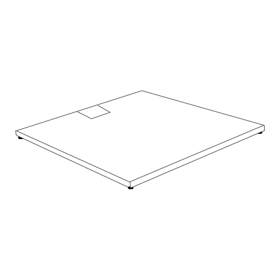
- Page 1 Installation Manual Floor Scale 50612 / SJ4747 © 2002 by Fancor. All rights reserved Issue 8 12/02...
- Page 2 Every effort has been made to provide complete and accurate information in this manual. However, although this manual may include a specifically identified warranty notice for the product, Fancor makes no representations or warranties with respect to the contents of this manual, and reserves the right to make changes to this manual without notice when and as improvements are made.
-
Page 3: Table Of Contents
......21 Appendix III: Pit Frame Installation Drawing ..... . 22 12/02 50612 / SJ4747 Issue 8... -
Page 4: Section 1: Introduction
Intalogix™ series using a Quad Multiplexer Box (QMB) for interfacing to an Intalogix™ Technology indicator. Note: It is the owner's responsibility to document, notify, and follow-up regarding shipping damage with the carrier. 12/02 50612 / SJ4747 Issue 8... -
Page 5: Section 2: Description
25 foot interface cable. All junction boxes are constructed of stainless steel and all models have threaded holes in the decks for attaching eyebolts to facilitate installation and cleaning. Specifications and sizes are included in a chart in Appendix I. 12/02 50612 / SJ4747 Issue 8... -
Page 6: Section 3: Installation
A. Analog Interface (Junction Box 67171) : L/C Wire Color Function Analog Instrument Black (-) Excitation (-) Excitation (+) Excitation (+) Excitation Yellow Shield Shield Green (+) Signal (+) Signal White (-) Signal (-) Signal 12/02 50612 / SJ4747 Issue 8... -
Page 7: Using Intalogix Technology Interface ( Qmb 15291)
Follow the appropriate indicator service manual to ensure a good calibration. To accomplish this: a. Perform a platform calibration that will be 'close' to the actual weight. b. Identify the platforms corner 'numbers'. 50612-1 12/02 50612 / SJ4747 Issue 8... - Page 8 CCW position (until a clicking is heard when turned). Then with the weight on the lowest reading corner, turn the corresponding potentiometer CW to read the same as the highest reading corner until the platform is properly 'cornered'. 12/02 50612 / SJ4747 Issue 8...
- Page 9 When the corners are the same in reference to each other: Remove all weights Zero the indicator Perform a final calibration with test weights Follow the appropriate indicator service manual to ensure a good calibration. 12/02 50612 / SJ4747 Issue 8...
-
Page 10: Section 4: Accessories Installation
• If two ramps are installed, NO other bolt-down plates are needed • If one ramp is installed then a set of two bolt-down plates are needed • Only two ramps total may be installed on opposite sides of a scale platform. 12/02 50612 / SJ4747 Issue 8... -
Page 11: Bumper Guards
Use the drawing in Appendix III for measurements. 3. The hole will have to be deep enough to accommodate the pit coping, plus the thickness of the pit floor. Use the drawing in Appendix III for measurements. 12/02 50612 / SJ4747 Issue 8... - Page 12 • Cure to a minimum of 2000 psi before cutting wire. • Pull the cable through the conduit before placing the scale platform in the frame • Level the platform before installing the instrumentation 12/02 50612 / SJ4747 Issue 8...
-
Page 13: Section 5: Parts Replacement
Connect the load cell wires into the junction box, tighten the box gland bushing(s) then test and calibrate the scale. Replace the box cover and torque all screws to 18-20 in/lbs. Replace the platform access cover . 9. Recalibrate as necessary. 12/02 50612 / SJ4747 Issue 8... - Page 14 10. Load Cell Specifications: Specifications Material Mild Steel Resistance 350 Ohm Rated Output 3 mV/V Safe Overload 150 % CompensatedTemp Range -10° C to 40° C Safe Operating Temp Range -10° C to 40° C 12/02 50612 / SJ4747 Issue 8...
-
Page 15: Junction Box/Qmb Pcb Replacement
4. Lower the scale to the surface removing the safety blocks. 5. Ensure that the weight is shared evenly by all four (4) feet. 6. Replace the hole plug in the access hole. 12/02 50612 / SJ4747 Issue 8... -
Page 16: Section 6: Parts
NOTE: Older 2000 and Avenger Series used an EVO type corner network ( 1.75” X 5” ) Part No. 97025 If complete assembly is required Box and Board, order Part No. 67171 as the new style replacement 12/02 50612 / SJ4747 Issue 8... - Page 17 Analog Series: 50612-2 12/02 50612 / SJ4747 Issue 8...
-
Page 18: Intalogix Technology Series
Liquid Tight Connector 63586 Hole Plug, 5/8" 54203 SS Hex Nut 10-24 (for ground) 14721 5" Velcro Loop (use with hook) 14722 5" Velcro Hook (use with loop) 11175 Rubber Bushing (for #11 conn) 12/02 50612 / SJ4747 Issue 8... - Page 19 Intalogix™ Technology Series: 50612-3 12/02 50612 / SJ4747 Issue 8...
-
Page 20: Appendix I: Model Matrix
4' x 6' 10000 lbs 63525 63640 5' x 5' 5000 lbs 63493 63641 5' x 5' 10000 lbs 63493 63642 5' x 7' 5000 lbs 63495 63643 5' x 7' 10000 lbs 63495 12/02 50612 / SJ4747 Issue 8... -
Page 21: Appendix Ii: Accessories
72192 (7') 63767 5' x 7' 63755(5') 72192 (7') 63767 B. Bolt-Down Plates, Eyebolts, and Hole plugs: Size Bolt-Down Plates Eyebolts Hole Plugs 63776 (Set of 4) 70895 (2) 70896 (2) 63778 (Set of 2) 12/02 50612 / SJ4747 Issue 8... -
Page 22: Appendix Iii: Pit Frame Installation
Appendix III: Pit Frame Installation 12/02 50612 / SJ4747 Issue 8...
Need help?
Do you have a question about the 50612 and is the answer not in the manual?
Questions and answers