
Related Manuals for Curtis Dyna-Fog MAXI-PRO 1 45 2 Series

Summary of Contents for Curtis Dyna-Fog MAXI-PRO 1 45 2 Series
- Page 1 ™ MAXI-PRO MODEL 2748 SERIES 2 Ultra-Low Volume Aerosol Generator MANUFACTURED BY: INSTRUCTION MANUAL FOR OPERATION, SERVICE AND MAINTENANCE 1 ...
- Page 2 Dyna-Fog is a registered Trademark Of Curtis Dyna-Fog, Ltd Maxi-Pro 1 is a Trademark of Curtis Dyna-Fog, Ltd. This product is protected by one or more of the following patents: U.S. PATENTS: 5,299,737, 6,206,300 Other U.S. and Foreign Patents Pending.
-
Page 3: Table Of Contents
TABLE OF CONTENTS MACHINE SPECIFICATIONS…………………………….…………..…………………5 MAJOR COMPONENTS DIAGRAM…………………………………..………………..6 FORWARD………………….…………………………………………………………...…7 DESCRIPTION………………..……………………………………………………………7 WORKING PRINCIPLES.……………………………….………………………………..8 FLUID SYSTEMS DIAGRAM…………………………………………….………………9 REMOTE CONTROL BOX FUNCTIONS……………………………………..…….…10 ASSEMBLY INSTRUCTIONS…………………………………………..…………..11-13 MACHINE INSTALLATION……………………………………………………..………13 SAFETY PRECAUTIONS..................14-16 OPERATION......................16-25 PRE-SPRAY CHECK LIST................17 ENGINE PREPARATION.................18-19 STARTING THE ENGINE…………………………………………………..19-21 LIQUID FLOWABILITY MEASUREMENT..........22-23 TYPICAL INSECTICIDE FLOW RATE............24 PARTICLE SIZE TABLES ................25 SYNCROFLOW SECTION.................26-27 MAINTENANCE....................28-41... - Page 4 ASSEMBLY.......................43-44 PUMP CONTROL, OUTSIDE DIAGRAM............44 MACHINE ELECTRICAL SCHEMATIC REMOTE CONTROL BOX SCHEMATIC………………………………..….…45 PARTS IDENTIFICATION MACHINE DIAGRAM (EXPLODED VIEW)……………………………..…46-47 ENGINE ASSEMBLY 18 HP VANGUARD………………………………….…48 BLOWER ASSEMBLY………………………………………….…….……….…49 NOZZLE/BOOM ASSEMBLY……………………………………..………….…50 ULV NOZZLE ASSEMBLY…………………………………………….…….….51 FLEXIBLE COUPLING ASSEMBLY………………………………….…….….52 GASOLINE TANK ASSEMBLY………………………………….………….…..53 FORMULATION TANK ASSEMBLY WITH FILTER……………….…………54 FLUSH TANK ASSEMBLY………………………………………….………..…55 MACHINE PLUMBING DIAGRAM…………………………………………..…56 PLASTIC NUTS…………………………………………………………….…….57...
-
Page 5: Machine Specifications
MACHINE SPECIFICATIONS FOR MAXI-PRO 1 , MODEL 2748 SERIES 2 TYPE: Aerosol Generator, Non-Thermal, Insecticide, Ultra-Low-Volume, (ULV) ENGINE: Briggs & Stratton, 4-cycle, 2 cylinders, gasoline engine, 18 HP, equipped with electric starter alternator and remote electric choke. Normal Operating Speed: 2,450 – 2,700 RPM BLOWER: Positive displacement. -
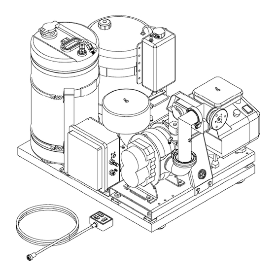
Page 6: Major Components Diagram
6 ... -
Page 7: Forward
FOREWORD The application of insecticides is the predominant method by which man attempts to control the size of insect populations. Due to environmental and economical reasons, it is desirable to treat a given area with the least amount of insecticide that can be made to be effective. -
Page 8: Working Principles
WORKING PRINCIPLES An 18 Horsepower, electric start, four-cycle gasoline engine with a flexible coupling on its output shaft is used to drive a positive displacement rotary-blower. The air entering the blower is first filtered through a large stainless steel filtering element. The blower supplies air pressure to the nozzle. - Page 9 9 ...
-
Page 10: Remote Control Box Functions
REMOTE CONTROL BOX FUNCTIONS MACHINE SWITCH OFF: Removes +12 V DC system power and grounds gasoline engine ignition to kill the engine. MACHINE SWITCH ON: Applies +12 V DC system power and removes ground from gasoline engine ignition. This position also applies power to Machine L.E.D. -
Page 11: Assembly Instructions
ASSEMBLY INSTRUCTIONS Uncrate the unit and remove all packing materials. NOTE: It is a good idea to retain the original machine shipping carton for storage. Place the remote control unit where it will not be damaged while the machine is being installed. Remove the machine from the shipping skid by removing the four lag screws that retain the mounting tabs. - Page 12 NOTE: The temperature of the battery and electrolyte at time of filling should be above 60 F (15 CAUTION NEVER FILL BATTERY IN MACHINE AS SPILLS WILL DAMAGE FINISH AND CAUSE PREMATURE CORROSION AND/OR DAMAGE TO COMPONENTS. Charge 12 volt battery at 3 - 4 amps until the acid temperature is above 80°F (26°...
-
Page 13: Machine Installation
After battery has been initially service, only water should be added to restore the liquid level in each cell. Further addition of acid will cause battery failure. MACHINE INSTALLATION Remove the machine from the skid and lift the machine onto the vehicle with the discharge end of the machine toward the rear of the vehicle. -
Page 14: Safety Precautions
WARNING NEVER ATTEMPT TO OPERATE THE MACHINE WITHOUT FIRST VERIFYING THAT IT IS SECURELY MOUNTED. FAILURE TO DO SO COULD RESULT IN SEVERE INJURY. SAFETY PRECAUTIONS WARNING READ AND UNDERSTAND THESE SAFETY PRECAUTIONS BEFORE OPERATING MACHINE ENGINE AND FUEL: This machine uses gasoline for the internal combustion engine and all precautions commonly applying to this volatile gasoline should be observed. - Page 15 MACHINE DAMAGE: Never operate a machine after it has been damaged. A damaged machine can be very hazardous. WIND: Spraying during windy conditions is not usually practical because the formulation will drift out of the intended area. However, under NO circumstances should spraying into the wind be attempted.
-
Page 16: Operation
a. Always comply with any requirements for protective clothing, goggles, gloves, facial masks, or respirators required on the formulation label. b. Do not exceed the dosage set forth on the registration label of the insecticide to be used. c. Always store formulation in its original labeled container. 7. -
Page 17: Pre-Spray Check List
WARNING DO NOT USE ANY SUBSTANCES FROM UNMARKED CONTAINERS OR FROM CONTAINERS WITH OBVIOUSLY ALTERED LABELS. READ AND FOLLOW THE INSTRUCTIONS ON THE CHEMICAL SOLUTION LABEL FOR ULV SPRAYING OF THE SOLUTION. DO NOT SPRAY NEAR AN OPEN FLAME OR HOT MATERIALS. DO NOT LEAVE THE MACHINE UNATTENDED. -
Page 18: Engine Preparation
CAUTION BEFORE PROCEEDING WITH ANY SPRAYING OPERATION, THE OPERATOR SHOULD BE THOROUGHLY FAMILIAR WITH STARTING AND STOPPING THE MACHINE AND WITH ALL THE OPERATING CONTROLS. IF YOU ARE OPERATING THE MACHINE FOR THE FIRST TIME, EXERCISE THE MACHINE THROUGH ITS FULL OPERATIONAL SEQUENCES FROM A POSITION OF FULL VISIBILITY OF THE MACHINE BEFORE OPERATING THE MACHINE FULLY REMOTE. -
Page 19: Starting The Engine
Oil capacity is about 1.5 quarts (1.4 liters) if engine is not equipped with oil filter. Oil capacity is about 1.75 quarts (1.7 liters) if engine is equipped with oil filter. Note: Engine is shipped from factory without oil. Before starting the engine, check oil level. -
Page 20: Choke Control
CHOKE CONTROL ON/OFF SWITCH SPEED CONTROL 3. TURN "ON" (RUN) THE "RUN/STOP" SWITCH: Position the keyed ON/OFF switch or starter toggle switch on engine to "ON" position. START ENGINE: Activate the spring-loaded starter switch on the engine or activate the toggle switch on the remote control box to the start position. NOTE: To prevent overheating the engine starter motor, do not activate the motor longer than 15 seconds at a time. - Page 21 Adjust the engine Speed control to achieve the desired Boom Pressure. Pulling the control rod increase the engine speed (increase the boom pressure). The engine speed control is located close to the cap of the oil level indicator (dipstick). ...
-
Page 22: Liquid Flowability Measurement
MEASURING LIQUID FLOWABILITY (VISCOSITY) In order to achieve consistent results in generating aerosols with a volume median diameter (VMD) in the sub 20 micron range, several variables must be kept under control at the same time. The ability of an aerosol generator to consistently break up a liquid into appropriate sized droplets depends on (3) key elements: The available energy flow (air flow) through the nozzle is governed by the blower speed. - Page 23 To measure the flowability (viscosity) of your formulation: 1. Place a sample of the formulation liquid to be dispensed in the relative flowability meter provided with the machine such that the liquid level is above the top line. 2. Hold the meter vertical and allow the liquid to flow through the brass orifice at the outlet end of the meter into an appropriate container.
-
Page 24: Typical Insecticide Flow Rate
TYPICAL FLOW RATES FOR INSECTICIDES TABLE 1 FLOW RATE DOW MFC PYRETHRIN DIBROM VEHICLE DURSBAN TECHNICAL SPEED MPH (CHLORPYRIFOS) MELATHION OZ/MIN OZ/MIN OZ/MIN OZ/MIN OZ/MIN 1.4-2.7 .33 - .66 2.0-2.5 3.0-6.0 1.0-2.1 2.7-5.3 .66-1.33 4.0 - 5.0 6.0-12.0 2.0-4.3 — 1.0-2.0 6.0-7.5 9.0-18.0... -
Page 25: Particle Size Tables
PARTICLE SIZE (VMD) IN MICRONS In RESPECT TO FLOW RATE AND BOOM PRESSURE TABLE 2 DIBRON (NALED) (TIME THROUGH FLOW METER APPROX. 34 SECONDS) LIQUID LIQUID BOOM PRESSURE FLOW RATE FLOW RATE OZ/MIN ML/MIN 8PSI 6PSI 4PSI 3PSI 2PSI 4.7 VMD 5.7 VMD... -
Page 26: Syncroflow Section
™ SYNCROFLOW SYSTEM ™ When equipped, the Curtis Syncroflow System allows the dispensing of formulation to be either a constant flow ("manual") regardless of vehicle speed, or a ™ variable flow ("Syncroflow ") which is correlated to vary proportionately with vehicle speeds from 0 to 20 m.p.h. - Page 27 Start the vehicle in motion and place the OUTPUT switch on the ON position. Adjust the knob for the rate of flow specified by the formulation label that pertains to your vehicle speed. Example: If a formulation label calls for an output of 3 oz at 5 MPH (89 ml at 8 Km/h), 6 oz at 10 MPH (177 ml at 16 Km/h), 9 oz at 15 MPH (266 ml at 24KM/h), and 12 oz at 20 MPH (335 ml at 32 Km/h), you may set the flow rate at any of these speeds.
-
Page 28: Maintenance
PREVENTIVE MAINTENANCE NOTE: A successful maintenance program begins after the first use of the machine and not after the machine has ceased to function. PREVENTIVE MAINTENANCE: Occasionally inspect mounting hardware to ensure that fasteners are tight. Loose hardware can cause excessive vibration leading to major failure of components. -
Page 29: Maintenance Schedule
MAINTENANCE SCHEDULE TABLE 5 NOTE: Change oil more often when operating in high ambient temperatures. Clean air filters more often under dusty conditions or when airborne debris is present. See engine and blower manuals. 29 ... -
Page 30: Flushing The System
FLUSHING SYSTEM The system must be flushed after each use to protect the equipment from the corrosive material in the formulation. CAUTION Never handle any parts on the machine that come in contact with formulation until the unit has been thoroughly flushed with isopropyl alcohol or other recommended flushing agent. -
Page 31: Formulation Filter
FORMULATION FILTER The system is equipped with an in line low profile filter located at the formulation tank standpipe. This filter is to prevent any foreign matter from entering the 3-way solenoid valve and the nozzle system. Located inside the filter housing are a fine mesh stainless steel screen and an Aflas gasket seal. -
Page 32: Blower Filter
FILTER - SILENCER (Rotary Blower) General: The air blower filter - silencer is mounted on the air blower. Dirt and other foreign particles are filtered from the incoming air by means of the reusable stainless element. The design is such that it partially silences the air also. Note: DO NOT run the machine without this filter - silencer assembly, as this would cause serious damage to the blower unit. -
Page 33: Ulv Nozzle Assembly
ULV NOZZLE ASSEMBLY The design of the ULV Nozzle is such that it should require little maintenance if the machine is properly flushed after each use. However, if it becomes necessary to clean the entire Nozzle Assembly, refer to steps 1-7. To inspect the inside of the Nozzle it is not necessary to remove the entire Nozzle Assembly from the machine. -
Page 34: 3-Way Solenoid Valve
3- WAY SOLENOID VALVE ASSEMBLY (INSTRUCTIONS FOR REBUILDING AND CLEANING) Using a screwdriver, snap off the retaining clip which secures the coil assembly. Remove the retaining clip, the nameplate spacer, and the coil housing. Slide the coil off the valve body, and using a spanner nut (P/N 62650-15), remove the core housing for cleaning or rebuilding. -
Page 35: Formulation Pump Calibration
PUMP – FLOW VALIDATION (CALIBRATION) Before attempting to spray, the FMI pump must be calibrated to the proper flow rate setting. The required flow rate is dictated by the information on the formulation manufacturer's label. Calibration Steps: 1) Loosen the two locking knobs and position the indicator to the setting in the Flow Table below that is closest to your desired output. - Page 36 CURTIS DYNA-FOG, LTD. *Flow Rate vs. Pump Setting *Flow Rate Pump Setting Oz/min (ml/min) 2.2 (65) 4.4 (130) 6.5 (192) 8.5 (250) 10.5 (310) 12.5 (370) 13.2 (390) 13.9 (410) 14.5 (429) 15.2 (450) *Flow test parameters: Machine: Pro-Maxi FMI Media pumped: Water Pumping system: FMI Metering Pump (1/4”...
-
Page 37: Hi-Flex Coupling Installation
HI-FLEX COUPLING INSTALLATION INSTRUCTIONS FLANGE AND BUSHING INSTALLATION Make sure the bore and tapered cone surface of the bushing and flanges are free of all foreign substances such a paint or dirt. 1. Place *QD bushing on the shaft over the key with flange end first. The end of bushing should be flush with the end of the shaft for best results. - Page 38 CAUTION : NEVER ALLOW THE FLANGE ASSEMBLY TO BE DRAWN IN CONTACT WITH THE FLANGE OF THE *QD BUSHING. THERE SHOULD BE A GAP FROM 1/8" TO 1/4" BETWEEN THEM. IF THE GAP IS CLOSED, THE SHAFT IS SERIOUSLY UNDERSIZED. Bolts of *QD Bushing: 1/4-20 x 1-1/4, grade 5.
- Page 39 FOR PARALLEL AND NON PARALLEL SHAFTS : For the longest coupling life is always best to align couplings as accurately as possible upon the initial installation. INSTALLATION OF FLEXIBLE ELEMENT 5. You may loosen the flange assembly screws as much as possible without disassembly of cover or you may remove the screws completely thus disassembling the cover.
-
Page 40: Storage And Shipment
STORAGE & SHIPMENT PREPARING THE BLOWER FOR STORAGE In preparing the blower for storage, the inner workings of the blower must be coated with a rust inhibiting oil. This is done by removing the air filter/silencer cover. After the filter/silencer cover is removed, access to the inner workings is possible. A rust inhibitor can then be sprayed into the blower while rotating the blower shaft to insure all parts are oiled. - Page 41 PREPARING THE BATTERY FOR STORAGE Disconnect positive (+) and negative (-) battery cables and wrap cable ends with electrical tape. Remove battery and store in a cool dry area. CAUTION WHEN DISCONNECTING OF THE BATTERY IS REQUIRED, REMOTE NEGATIVE (-) CABLE FIRST. PREPARING THE FRAME ASSEMBLY FOR STORAGE The frame should be wiped down with Isopropyl Alcohol and dried.
-
Page 42: Bypassing The Pressure Switch
PASSING THE AIR PRESSURE SWITCH PRESSURE SWITCH PUMP AND CONTROL ASSEBLY (RELATIVE LOCATION OF PRESSURE SWITCH) The air pressure switch is part of the logic of the circuit, allowing the operation of the formulation pump only if the air nozzle boom pressure is present. With this feature, the machine is not able to pump (spill) the formulation with the engine/blower off (stopped). - Page 43 OUTSIDE CONTROLS AND COMPONENTS 43 ...
- Page 44 PUMP CONTROL ASSEMBLY ENCLOSURE AY, FMI PUMP P/N 64656 ITEM DESCRIPTION ITEM DESCRIPTION 63968-4 ENCLOSURE, MACH, F-PUMP 64691 HARNESS AY, FMI PUMP 74275 LOUVER, MIDGET 159336 SCREW, 6-32 x ½, PNCR 64694 REGULATOR AY, VOL FMI 54026-1 FUSE, 15A, 250V 22083-31 TUBE, POLY, 66P, .375 54049...
-
Page 45: Remote Control Box Schematic
REMOTE CONTROL BOX SCHEMATIC FMI PUMP BLACK BLACK RED/BLACK RED/BLACK BLUE BLUE GREEN GREEN GREEN ORANGE COM NO PRESSURE SWITCH VOLTAGE REGULATOR BLACK 45 ... -
Page 46: Machine Diagram (Exploded View)
46 ... - Page 47 ITEM DESCRIPTION ITEM DESCRIPTION 63268 TIE DOWN A.Y. 63327 FOOT, EPDM RUBBER 64004-1 FORMULATION TANK AY 49053 BUMPER, RUBBER 2.5” 63860 TANK AY, FUEL 12.2 GAL. 62826 FRAME AY., WELDED 79110-1 LABEL, LOGO (BLUE) 121900 BOLT, 1/4-20 X 1 64656 FMI PUMP ENCLOSURE 62628 REMOTE CONTROL CABLE...
-
Page 48: Engine Assembly 18 Hp Vanguard
ENGINE ASSEMBLY P/N: 62799-10 ITEM QUANTITY PART NUMBER ITEM DESCRIPTION 62799 ENGINE, 18 HP, VANGUARD 190254 NUT, 10-24 LOCK HEX 64016 HOURMETER / TACHOMETER 85685 CONNECTOR 3M 63285-1 CLAMP, CABLE 5/8 49078 HARNESS, ADAPTER (B&S) 63186 BOLT, M8-1.25 x 16, HEX 138485 WASHER, LOCK, 5/16, EXT 120393... -
Page 49: Blower Assembly
BLOWER ASSEMBLY P/N: 63461-2 ITEM QUANTITY PART NUMBER ITEM DESCRIPTION 62809 BLOWER, ROOT 5.45 32828 ELBOW & ORIFICE AY 62871 CUTPUT FLANGE AY 62805 LOCKING RING 62851 FILTER SILENCER 62823 ELBOW, INPUT 62824 NIPPLE 2.5 NPT X 3.5 63438 BOLT, .25-20 X 1.5 GRADE 8 138542 WASHER, LOCK 3/8, INTO 120388... -
Page 50: Nozzle/Boom Assembly
BOOM AY, 61635-4 ITEM QUANTITY PART NUMBER ITEM DESCRIPTION 62861-1 TEE/TUBE AY. 62419 KNOB, QK, RELREASE 64630-1 NOZZLE AY., SPRAY 63019 CLAMP, V-INSERT 64626 NOZZLE TUBE WELD AY. 145463 NUT, 1/4 TUBE 10100-10 O-RING 62550-1 NUT, .250, STL GRIP 62555-1 ELBOW, UNION, 1/4 T 62582-1 NUT, .250, PLST GRIP... -
Page 51: Ulv Nozzle Assembly
ULV NOZZLE ASSEMBLY P/N: 64630-1 ITEM QUANTITY PART NUMBER ITEM DESCRIPTION 64650 TUBE, NOZZLE SPRAY 64647 BODY, NOZZLE 10100-153 O’RING, 3.693 O.D. 64649-2 DISC, NOZZLE, MACHINED 64643 SCREW, #10-24 X 3/8, SST 64642 SCREW, #6-32 X 3/8, SST 64601 CONE, NOZZLE, ANODIZED 422987 NUT, .250, STL GRIP ... -
Page 52: Flexible Coupling Assembly
FLEXIBLE COUPLING ASSEMBLY P/N 67087-3 ITEM QTY. PART NUMBER DESCRIPTION 62549 KEY, 1/4 X 1.75 63460-7 BUSHING, TYPE SH, 1” 67087 FLANGE AY., SH70 63460-6 BUSHING, TYPE SH., .875”... -
Page 53: Gasoline Tank Assembly
TANK ASSEMBLY, GASOLINE 12.2 P/N 63860 ITEM QUANTITY PART NUMBER ITEM DESCRIPTION 64088-1 TANK, 12.2 GAL., MACHINED 62578-4 CAP WITH GAUGE 85520 LABEL, GASOLINE 62563-5 STANDPIPE, SSTU, .25 10105 CONNECTOR, STANDPIPE 114628 SLEEVE, 1/4 T 145463 NUT, 1/4 T ... -
Page 54: Formulation Tank Assembly With Filter
FORMULATION TANK ASSEMBLY WITH FILTER P/N 64004-1 ITEM QUANTITY PART NUMBER ITEM DESCRIPTION 62574 FORMULATION STANDPIPE AY 62545 FORMULATION STANDPIPE 62550-3 NUT, .375 STL GRIP 62573-2 CONNECTOR, MALE MOD. 63094 LABEL, FORMULATION 64077 CAP AY, MALE FILL 2” 64002 TANK, 15 GAL NAT POLY 64772 BUSHING, 3/4 MPT X 3/8 FPT, NYL 62554-4... -
Page 55: Flush Tank Assembly
FLUSH TANK ASSEMBLY (1 GALLON), P/N: 63337-1 ITEM QUANTITY PART NUMBER ITEM DESCRIPTION 63302-6 TANK, 1 GAL. (MACHINED) 62592 LABEL, FLUSH 62553-1 CONNECTOR, UNION, 1/4 T 62550-1 NUT, .25, STEEL GRIP 114628 SLEEVE, 1/4 T 145463 NUT, 1/4 T 10105 CONNECTOR, STANDPIPE 53131 WASHER, FLAT... -
Page 56: Machine Plumbing Diagram
MAXI-PRO 145™ PLUMBING DIAGRAM ITEM QUANTITY PART NUMBER ITEM DESCRIPTION 62582-3 NUT, 3/8”, PLASTIC GRIP 62586-11 TUBE, 3/8” OD 62582-1 NUT, 1/4”, PLASTIC GRIP 62584-7 TUBE, 1/4" OD 62584-21 TUBE, 1/4" OD 62584-18 TUBE, 1/4" OD 145463 NUT, 1/4"... -
Page 57: Plastic Nuts
57 ... -
Page 58: Automatic Engine Idleback (Optional)
IDLEBACK KIT, P/N: 63875 ITEM QUANTITY PART NUMBER ITEM DESCRIPTION 120854 BOLT HEX 1/4-20 X 5/8” 120392 WASHER, FLAT 1/4 REG 121753 WASHER, LOCK 1/4 EXTO 134551 NUT, HEX 1/4-20 63850 SOLENOID, 12V DC 62693-140 WIRE ASSEMBLY, BLACK 20247 TIE, CABLE 63849 ENCLOSURE, RELAY... -
Page 59: Troubleshooting
TROUBLESHOOTING SYMPTOMS POSSIBLE CAUSE CORRECTIVE ACTION 1. Starter fails to crank engine. a. Battery cable connections. a. Clean & tighten cable; loose, dirty or damaged connections. Replace a damaged cable. b. Dead battery. b. Replace or charge battery. c. Defective starter switch Check starter button... - Page 60 SYMPTOMS POSSIBLE CAUSE CORRECTIVE ACTION 6. Engine overheats. a. Crankcase oil low. a. Add oil to proper levels. b. Air shroud clogged. b. Clean or replace air shroud. c. Exhaust restricted. c. Replace muffler. d. Spark arrester clogged. d. Clean or replace. 7.
- Page 61 SYMPTOMS POSSIBLE CAUSE CORRECTIVE ACTION 13. Machine light not on. a. Blown fuse. a. Eliminate Short and replace fuse. b. Battery not connected. b. Connect battery. c. Control ground disconnected. c. Check ground for physical and electrical connection to chassis. Outside of test connector should read 0 ohms to chassis.
- Page 62 Diversity of pumping systems, Gear, Piston and Diaphragm. Pressurized system available for overseas market. Optional Radar Syncroflow. 40 cc Two cycle portable machines also available. ® 17335 US Highway 31 North CURTIS DYNA-FOG Ltd. Westfield, IN 46074 U.S.A. www.dynafog.com www.dynafog.com Phone: (317) 896-2561...
Need help?
Do you have a question about the MAXI-PRO 1 45 2 Series and is the answer not in the manual?
Questions and answers