Advertisement
Quick Links
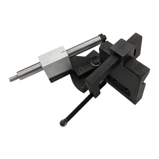
SUMMIT RACING® TUBING & PIPE NOTCHER HOLE SAW
Features & Benefits:
•
Bolts to a Work Bench or Clamps in Your Vise
•
Notches Tubing from ¾" to 3.0" Diameter from 0^ to 50^ Angles
•
Includes a Threaded Chuck to Accept Standard Thread Hole Saws
•
Needle Bearings Allow Drilling Shaft to Slide Effortlessly In & Out of Tubing to Produce Perfect, Repeatable Cuts
(Notches)
Special Notes & Precautions:
•
Make Sure All Mating Surfaces, Metal to Metal and Threaded Holes Are Liberally Lubricated to Avoid Galling and
Binding.
•
The Same Can Be Said for Storing When Not in Use. Keep Lubricated.
•
ALWAYS Lubricate Your Hole Saw Each Time Before Cutting Notches with Cutting Oil.
This avoids dulling of the hole saws
•
Whenever Using Electric or Pneumatic Drill Motors or Other Machining Equipment, Use Standard Safety Rules Like
Wearing Safety Glasses and Gloves. Keep Loose Clothing Away from Moving Parts.
•
Never Expose This Device to Moisture. Steel Rusts
•
This Device is Very Dangerous. Keep Away from Children!
•
Always Confirm None of the Moving Parts Are in Bind, They should All Move Freely
Please read these instructions in their entirety. There are several key points that are made throughout
the Installation / Operations / Assembly Instructions that should be met.
1200 Southeast Ave
Tallmadge Ohio 44278
Part # SUM-900217
Advertisement

Summary of Contents for Summit Racing SUM-900217
- Page 1 1200 Southeast Ave Tallmadge Ohio 44278 SUMMIT RACING® TUBING & PIPE NOTCHER HOLE SAW Part # SUM-900217 Features & Benefits: • Bolts to a Work Bench or Clamps in Your Vise • Notches Tubing from ¾” to 3.0” Diameter from 0^ to 50^ Angles •...
- Page 2 Bill of Materials...
- Page 3 Assembling Your Machine Fig 1 Fig 2 Place #1, the slider, over #2, the tubing clamp and then mate the grooves as a group over #4, the main tubing structure - (Fig 1) Install #5, M10 x 16 bolt, slider stop into the end of the main tubing structure. – (Fig 2) Fig 3 Fig 4 Insert #9, the plunge shaft into #7, the bearing block, then place the assembly onto #10, the arc plate guide and...
- Page 4 Final Notes & Precautions Before Operation: • Mount Notcher in a Vise or Mount Directly to a Work Bench. Your Machine MUST BE Hard Mounted Prior to Notching to Avoid Bodily Injury. o You may use a C-clamp to capture the part to the bench o You can install bolts (not included) through the two ½”...
Need help?
Do you have a question about the SUM-900217 and is the answer not in the manual?
Questions and answers