Chapters
Table of Contents

Subscribe to Our Youtube Channel
Related Manuals for Weh TK20-S1 H2 70 MPa ENR


Summary of Contents for Weh TK20-S1 H2 70 MPa ENR
- Page 1 Operating instructions ⋅ Betriebsanleitung Date: 10/24 Typ TK20-S1 H 70 MPa ENR | C1-186104 Hydrogen fueling nozzle ® Füllkupplung zur Wasserstoffbetankung ® - We Engineer Hightech ®...
- Page 3 LANGUAGES TYPE TK20-S1 H2 70 MPA ENR | C1-186104 � � � � � � � � � � � � � � � � � � � � � � � � � � � 4 Hydrogen fueling nozzle ®...
-
Page 4: Table Of Contents
Operating instructions Type TK20-S1 H 70 MPa ENR | C1-186104 Hydrogen fueling nozzle ® CONTENTS INTRODUCTION For your guidance General information Warranty and liability General safety instructions Definition of qualified personnel INTENDED USE PRODUCT OVERVIEW / PRODUCT DESCRIPTION TECHNICAL DATA STORAGE Safety instructions for proper storage Storage... - Page 5 11.2 Safety instructions for connecting the service receptacle 11.3 Checking the leak rate INSPECTION AFTER SEPARATION TROUBLESHOOTING DISPOSAL ACCESSORIES | SPARE PARTS The German version is the original. Manufacturer: WEH GmbH Gas Technology - hereafter referred to as 'WEH'. Page 5 MD-10455-L51-R1.2.0-07...
-
Page 6: Introduction
Operating instructions 1. INTRODUCTION Dear Customer! Thank you for deciding to use our products. The WEH Fueling Nozzle TK20-S1 H 70 MPa ENR was specifically developed for refu- ® eling vehicles with compressed gaseous hydrogen (CGH Observe and follow all instructions and warnings in these operating instructions�... -
Page 7: General Information
- You are solely responsible for the proper performance of the replacement or repair. WEH is not responsible for the performance or any damage and/or losses arising from it. WEH assumes no guarantee, warranty, product liability or other liability for any replacement or repair of the WEH ®... -
Page 8: General Safety Instructions
Î Take appropriate safety measures if operating conditions exist that could endanger the user. Î In case of any damage that may affect the proper functioning of the WEH Product, ® do not use the WEH Product until the situation has been clarified. Disassembly of ®... -
Page 9: Definition Of Qualified Personnel
Operating instructions Î Do not apply any external forces to the WEH Product. Therefore, do not lean on the ® (connected) WEH Product, do not hang on the WEH Product and do not climb on ® ® the WEH Product under any circumstances. In addition, refrain from hammering on ®... -
Page 10: Intended Use
Always ensure that the WEH Product is used only within the range of its intended ® use. Please note in particular the technical data of the WEH Product in chapter 4 on ® page 12 as well as the marking on the WEH Product itself. -
Page 11: Product Overview / Product Description
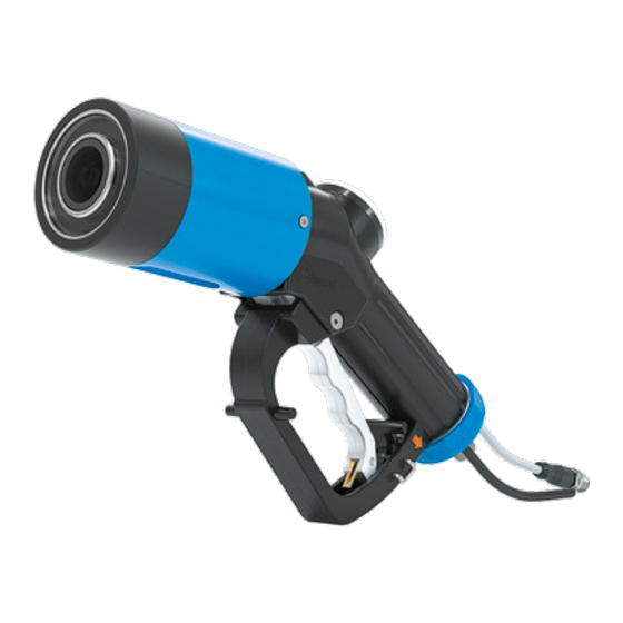
Operating instructions 3. PRODUCT OVERVIEW / PRODUCT DESCRIPTION TK20-S1 H 70 MPa ENR Pos� Description Impact protection sleeve Logo cap 260° swivel joint (plastic thermal protection) Definition of ports Locking lever Media inlet Actuation lever Purging line Hand grip Data cable Data interface (inside) Purging line... -
Page 12: Technical Data
Operating instructions 4. TECHNICAL DATA TK20-S1 H 70 MPa ENR Characteristics Basic version Nominal bore (DN) fueling 5 mm nozzle Nominal bore (DN) 4 mm fueling nozzle Pressure range fueling PN = 70 MPa | PS = 96.25 MPa (= MAWP gemäß ISO 19880- nozzle 1:2020) Flow rate during purging *... - Page 13 Operating instructions Data interface Characteristics Basic version Signal input format J2799 Signal output format RS485 Sensitivity level 0.57 - 0.060 A/W Band width 870 - 950 nm Mains voltage 5 V DC Minimum voltage 3.7 V Allowable current 30 mA Allowable power 16 V supply voltage...
-
Page 14: Storage
Î Store the WEH Product within a temperature range of -40 °C up to +40 °C. ® Storage temperatures outside this range may affect the service life of the WEH ® Product. Î Do not store the WEH Product in the vicinity of heat sources. -
Page 15: Storage
Follow the safety instructions in chapter 5.1 on page 14 and observe the following storage times. The allowable storage time is valid from the date of delivery (in- voice/goods issue date from WEH or the distributor) on the label of the packaging. If the WEH Product is installed in a complete system, the storage time depends on ®... -
Page 16: Required Tools
Operating instructions 6. REQUIRED TOOLS Mainte- Checking the Part no� Description Installation nance & leak rate Lubrication TNS1 H Service ® C1-148079 receptacle WKZ-148012 Assembly tool ® Open-ended wrench A/F15 Calibrated torque wrench (suitable for corresponding torque) Hexagonal bit insert A/F2 (suitable for corresponding torque) Hexagonal... -
Page 17: Installation
Ensure that the system is depressurized. Installation must only be effected in de- pressurized condition. Î Before installation, check if the counterparts are designed to withstand the assembly data (see chapter 7.2 Installation of filling hose on page 18) that WEH determined for this WEH Product. ®... -
Page 18: Installation Of Filling Hose
For purging, connect the purging line 'P1' of the fueling nozzle to your nitrogen resp. compressed air line. Use a suitable push-in connector (not included in the scope of delivery of WEH) for connection of the purging line. Attention: Only use nitrogen for purging dew point < -40 °C). -
Page 19: Connecting The Data Cable
Attention: The guiding pin of the data cable connector must engage in the groove of the inter- Groove face cable connector (Figure 3 and Figure 4). Please note: For torque tightening, the WEH Assembly ® tool part no. 148012 can be used. Figure 4 7�6... -
Page 20: Optimization Of Fueling Nozzle At A Fueling Station With A Dispenser Mounting With Integrated Purging System
Operating instructions 7�8 Optimization of fueling nozzle at a fueling station with a dispenser mounting with integrated purging system If you are using a dispenser mounting with integrated purging system, proceed as follows: Î Unscrew the two countersunk screws from the impact Pos. -
Page 21: Operation
8�1 Safety instructions for operation Î Only apply pressure to the fueling nozzle when it is connected to the receptacle of a vehicle or a WEH Service receptacle. ® Î Only actuate the fueling nozzle when it is connected to the receptacle of a vehicle or a WEH Service receptacle. -
Page 22: Connecting
Operating instructions 8�2 Connecting Î Remove the fueling nozzle from the dispenser. The actua- tion lever (Pos. 5) must be in the OFF position (Figure 10). Î Push the fueling nozzle onto the receptacle on the vehicle until it stops and hold the nozzle in this position (OFF position) (Figure 11). -
Page 23: Disconnection
Operating instructions 8�3 Disconnection Î After the fueling process has been completed and the hose has been fully vented, disconnect the fueling nozzle. Î Pull the locking lever (Pos. 4) back in the direction shown by the arrow(Figure 14), to release the locking mechanism and move the actuation lever into its OFF position. -
Page 24: Inspection | Maintenance
Do not damage sealing surfaces or sealing components. Î Before reassembling; check the components, threads and, if present, the sealing surfaces for damage and contamination. If you notice any damage , replace the WEH ® product or send it to WEH for maintenance. The WEH Product may no longer be ®... -
Page 25: Maintenance Intervals
Product immediately to WEH for mainte- ® nance. Products that are used at sea or in the vicinity of the sea must be sent to WEH for maintenance after one year at the latest. If you do not regularly inspect the WEH product and send it to WEH for mainte- ®... -
Page 26: Overview Of Minimum Intervals For Inspection And Maintenance
* Lubrication of the actuation (see chapter 10.2 Lubrication on page 36) Return to WEH for in-factory maintenance * depending on what happens first Note: For component arrangement see chapter 3. Product overview / product descrip- tion on page 11. -
Page 27: Maintenance
WEH Product must ® no longer be used. Immediately send the fueling nozzle to WEH for maintenance. The following maintenance steps may be carried out by the operator: Î Check the fueling nozzle for leak tightness, correct function and ease of movement. - Page 28 Should the label plate come loose or break, however (e.g. due to the nozzle falling to the ground), a new label plate can be affixed to the handle protection. Î Apply a thin layer of WEH ® Adhesive, to the three areas marked in red in.
- Page 29 Operating instructions 9�4�4 Replacing the locking lever (Pos 4) Please note: Replacing the locking lever (Pos 4), the existing clamp is reused. The clamp need only be replaced if it is lost or damaged. Î Remove the clamp from the hand grip (Pos.
- Page 30 Operating instructions 9�4�5 Replacing the hand grip (Pos 6) Î Clamp the dismantled fueling Hand grip nozzle e.g. into a vice with vertical plastic jaws. The Hand grip (Pos. 6) must point vertically upwards. Attention: Do not damage the fueling nozzle when clamp- ing it.
- Page 31 Tightening torque: 2 Nm Î Connect the fueling nozzle to the WEH Service receptacle several times. The ® actuation lever (Pos. 5) must not become stuck or stiff when operated. Î...
- Page 32 Operating instructions 9�4�6 Check of data interface function (Pos� 8) und der Impact protection sleeve (Pos� 1) Attention: When replacing the data interface (Pos. 8) please make absolutely sure that the serial number engraved on the new data interface is identical to the serial number of the data interface already installed.
- Page 33 The o-ring must be present and seated correctly in the recess. Î Lubricate the inner surface of the new data interface (Pos. 8) mit dem WEH lubricant ® Part. No. E99-4. Page 33 MD-10455-L51-R1.2.0-07...
- Page 34 Operating instructions Î Press the fueling nozzle onto the new data interface (Pos. Attention: The connector of the fueling nozzle must be inserted into the connector port of the data interface. Î Screw the four new screws evenly using the Hexagonal bit insert A/F2.5 with ball head and a suitable torque wrench into the data inter-...
- Page 35 Operating instructions Î Push the new protective sleeve (Pos. 1) onto the filling and venting hose. Note: The hole pattern of the impact protection sleeve must be aligned with the counterpart! Attention: Do not apply high radial torque to the impact protection sleeve during as- sembly.
-
Page 36: Lubrication
3. Product overview / product description on page 11. 10�1 Safety instructions for lubrication Î Take care not to damage sealing surfaces or sealing components when lubricating. Î Only use WEH maintenance spray ® Art for lubrication. Nr. E99-44923. 10�2 Lubrication Î... -
Page 37: Checking The Leak Rate
3. Product overview / product description on page 11. 11�1 Measuring the leak rate using a concentration meter - A concentration meter can be used to determine whether the WEH Product is leak ® tight. Please observe these following instructions when using such a device for leak testing: Î... -
Page 38: Safety Instructions For Connecting The Service Receptacle
Operating instructions 11�2 Safety instructions for connecting the service receptacle Î Check the fueling nozzle and the WEH Service receptacle for contamination and ® damage. Î Make sure that the fueling nozzle is not under pressure. The fueling nozzle may only be connected and disconnected when depressurized. - Page 39 Pull the locking lever (Pos. 4) back in the direction of the arrow (Figure 24) to release the locking mechanism and move the actuation lever to the OFF position. Î Carefully pull the WEH Service receptacle straight out of ® the fueling nozzle (Figure 25).
-
Page 40: Inspection After Separation
Replace the filling and venting hose between fueling nozzle and breakaway coupling and between breakaway coupling and fueling station after each separa- tion. Î Return the fueling nozzle to WEH for inspection after the separation. Î Check the WEH Breakaway coupling for damage and leak tightness. If this is ®... -
Page 41: Troubleshooting
Operating instructions 13. TROUBLESHOOTING Page 41 MD-10455-L51-R1.2.0-07... - Page 42 Operating instructions Page 42 MD-10455-L51-R1.2.0-07...
-
Page 43: Disposal
TNS1 H ® To prevent damage in the fueling nozzle while purging or leak testing during mainte- nance in the course of which pressure is applied, we recommend the use of the WEH ® TNS1 H Service receptacle. This also serves to protect the fueling nozzle from dirt ingress during phases of non-use. - Page 44 CCC IR data interface(incl. 4 cylinder screws, 2 countersunk screws and o-ring) E69-157491 Label Î When ordering, please indicate the part no. marked on the WEH Product. ® Please note: For the correct use of WEH Spare parts, see chapter 9. Inspection | ®...
- Page 46 Betriebsanleitung Typ TK20-S1 H 70 MPa ENR | C1-186104 Füllkupplung zur Wasserstoffbetankung ® INHALT EINLEITUNG Zu Ihrer Orientierung Allgemeine Angaben Gewährleistung und Haftung Allgemeine Sicherheitshinweise Definition von Fachpersonal BESTIMMUNGSGEMÄSSE VERWENDUNG PRODUKTÜBERSICHT / PRODUKTBESCHREIBUNG TECHNISCHE DATEN LAGERN Sicherheitshinweise zum sachgerechten Lagern Lagern BENÖTIGTE HILFSMITTEL INSTALLIEREN...
- Page 47 11.1 Messung der Leckrate mittels eines Konzentrationsmessgerätes 11.2 Sicherheitshinweise zum Anschließen des Servicenippels 11.3 Überprüfen der Leckrate ÜBERPRÜFEN NACH DEM ABRISS FEHLERBEHEBEN ENTSORGEN ZUBEHÖR | ERSATZTEILE Die deutsche Version ist das Original. Hersteller: WEH GmbH Gas Technology - im Nachfolgenden „WEH“ genannt. Seite 47 MD-10455-L51-R1.2.0-07...
-
Page 48: Einleitung
Betriebsanleitung 1. EINLEITUNG Sehr geehrter Kunde! Wir freuen uns, dass Sie sich für den Einsatz unseres Produktes entschieden haben. Die WEH Füllkupplung TK20-S1 H 70 MPa ENR wurde ausschließlich zur Betankung ® von Fahrzeugen mit komprimiertem, gasförmigem Wasserstoff (CGH ) entwickelt. -
Page 49: Allgemeine Angaben
- ein Lieferschein - ein Original WEH Prüfprotokoll (nicht bei Ersatzteilen) - eine WEH Betriebsanleitung Î Wenden Sie sich umgehend an WEH oder den entsprechenden Vertriebspartner, falls Ihnen Unterlagen fehlen. 1�3 Gewährleistung und Haftung - Es gelten unsere allgemeinen Geschäftsbedingungen. -
Page 50: Allgemeine Sicherheitshinweise
Fachpersonal (siehe Kapitel 1.5 auf Seite 51) vorgesehen. Stellen Sie diese Be- triebsanleitung insbesondere dem Fachpersonal zur Verfügung, das für die ein- zelnen Phasen des Lebenszyklus (speziell für das Lagern, Installieren, Bedienen, Inspizieren und Warten, die Fehlerbehebung und Entsorgung) des WEH Produktes ®... -
Page 51: Definition Von Fachpersonal
® weder auf dem (angeschlossenen) WEH Produkt ab, lehnen Sie sich nicht daran ® an, hängen Sie sich nicht an das WEH Produkt und steigen Sie keinesfalls auf das ® Produkt. Unterlassen Sie zudem auf das WEH Produkt zu hämmern oder ®... -
Page 52: Bestimmungsgemässe Verwendung
Stellen Sie sicher, dass die aktuellen gültigen Vorgaben zur Reinheit und Qualität des Wasserstoffs für Fahrzeuge eingehalten werden. Î Stellen Sie stets sicher, dass das WEH Produkt ausschließlich innerhalb der bestim- ® mungsgemäßen Verwendung zum Einsatz kommt. Beachten Sie hierfür insbesondere... -
Page 53: Produktübersicht / Produktbeschreibung
Betriebsanleitung 3. PRODUKTÜBERSICHT / PRODUKTBESCHREIBUNG TK20-S1 H 70 MPa ENR Pos� Bezeichnung Stoßschutzhülse Logodeckel Drehdurchführung 260° (Kälteschutz) Begriffserklärung Anschlüsse Verriegelungshebel Betriebsmedienzuleitung Betätigungshebel Spülleitung Handgriff Datenkabel Datenschnittstelle (innenliegend) Spülleitung Seite 53 MD-10455-L51-R1.2.0-07... -
Page 54: Technische Daten
Betriebsanleitung 4. TECHNISCHE DATEN TK20-S1 H 70 MPa ENR Eigenschaften Standardausführung Nennweite (DN) 5 mm Füllkupplung Nennweite (DN) 4 mm Spülleitung PN = 70 MPa | PS = 96,25 MPa (= MAWP gemäß ISO 19880- Druckbereich Füllkupplung 1:2020) Durchflussrate während 500 Nl/h bei max. - Page 55 Betriebsanleitung Datenschnittstelle Eigenschaften Standardausführung Signaleingangsformat J2799 Signalausgangsformat RS485 Empfindlichkeitsstufe 0,57 - 0,060 A/W Bandbreite 870 - 950 nm Nennspannung 5 V DC Minimalspannung 3,7 V Zulässige Stromstärke 30 mA Zulässige 16 V Versorgungsspannung Datenspannung 0 - 5,5 V Pegel der Ausgangs- 0 - 6 V spannung Schutzklasse...
-
Page 56: Lagern
Sicherheitshinweise zum sachgerechten Lagern Î Stellen Sie sicher, dass die folgenden Sicherheitshinweise und Lagerzeiten stets ein- gehalten werden. Achtung: Eine nicht sachgerechte Lagerung des WEH Produktes kann zu einer un- ® sicheren Nutzung des Produktes führen und kann die Lebensdauer verkürzen. -
Page 57: Lagern
Beachten Sie die Sicherheitshinweise unter Kapitel 5.1 auf Seite 56 und halten Sie die nachfolgenden Lagerzeiten ein. Die zulässige Lagerzeit gilt ab dem Auslie- ferungsdatum (Rechnungs-/Warenausgangsdatum seitens WEH oder des Ver- triebspartners). Sollte das WEH Produkt in einem Komplettsystem verbaut sein, ®... -
Page 58: Benötigte Hilfsmittel
Betriebsanleitung 6. BENÖTIGTE HILFSMITTEL Überprüfen Warten & Artikelnummer Bezeichnung Installieren der Leckrate Schmieren C1-148079 Servicenippel TNS1 H ® WKZ-148012 Montagewerkzeug ® Gabelschlüssel SW15 Geeigneter kalibrierter Drehmomentschlüssel (passend für das entsprechende Drehmoment) Sechskant-Bit-Einsatz SW2 (passend für das entsprechende Drehmoment) Sechskant- Schraubendreher SW2 Kreuzschlitz-Bit-Einsatz PH2 (passend für das entsprechende Drehmoment) -
Page 59: Installieren
Produkt vorgibt, aus- ® gelegt sind. Hinweis: Diese Montagedaten (Drehmomente, Montagedrehungen etc.) sind Werte, die ausschließlich für die Komponenten gelten, die im Lieferumfang von WEH enthalten sind. Î Stellen Sie vor Inbetriebnahme sicher, dass die von Ihnen eingesetzten Schläuche und die Abreißsicherung für den Anwendungsfall (z. B. Befüllung mit tiefkaltem Medium) ebenfalls geeignet sind. -
Page 60: Füllschlauch Installieren
Hinweis: Bei Nichtverwendung der Spülleitung muss der Stopfen angeschlossen bleiben 7�4 Dichtheit der Verbindung prüfen Î Schließen Sie die Füllkupplung an den WEH Servicenippel an. Beachten Sie hierzu ® das Kapitel 11.2 Sicherheitshinweise zum Anschließen des Servicenippels auf Seite Î... -
Page 61: Datenkabel Anschließen
Achtung: Die Führungszapfen des Steckers des Daten- kabels muss in die Nut des Steckers des Schnittstellen- kabels eingreifen (Abbildung 3 und Abbildung 4). Bitte beachten: Zum Anziehen mit Drehmoment kann das WEH Montagewerkzeug Art. Nr. 148012 verwendet ® werden. Abbildung 4 7�6... -
Page 62: Füllkupplung An Tankstelle Mit Belüfteter Zapfsäulenhalterung Optimieren
Betriebsanleitung 7�8 Füllkupplung an Tankstelle mit belüfteter Zapfsäulenhalterung optimieren Gehen Sie wie folgt vor, wenn Sie eine Zapfsäulenhalterung mit Belüftungssystem einsetzen: Î Schrauben Sie die zwei Senkschrauben mit einem Sechs- Pos. 1 kant-Schraubendreher SW2 aus der Stoßschutzhülse Senkschraube (Pos. 1) heraus (Abbildung 7). Î... -
Page 63: Bedienen
Kapitel 3. Produktübersicht / Produktbeschreibung auf Seite 53. 8�1 Sicherheitshinweise zum Bedienen Î Beaufschlagen Sie die Füllkupplung nur mit Druck, wenn sie an einen fahrzeug- seitigen Tanknippel oder einen WEH Servicenippel angeschlossen ist. ® Î Betätigen Sie die Füllkupplung nur, wenn sie an einen fahrzeugseitigen Tanknippel oder an einem WEH Servicenippel angeschlossen ist. -
Page 64: Anschließen
Betriebsanleitung 8�2 Anschließen Î Nehmen Sie die Füllkupplung aus der Zapfsäule heraus. Der Betätigungshebel (Pos. 5) muss in der OFF-Stellung stehen (Abbildung 10). Î Stecken Sie die Füllkupplung bis zum Anschlag auf den Tanknippel im Fahrzeug auf und halten Sie die Kupplung in dieser Position (OFF-Stellung) (Abbildung 11). -
Page 65: Abschließen
Betriebsanleitung 8�3 Abschließen Î Nach Beendigung des Tankvorganges und vollständiger Entlüftung des Schlauches, schließen Sie die Füllkupplung Î Ziehen Sie den Verriegelungshebel (Pos. 4) in Pfeilrich- tung zurück (Abbildung 14), um den Verriegelungsmecha- nismus zu lösen und den Betätigungshebel in die OFF- Stellung zu bringen. -
Page 66: Inspizieren | Warten
Produkt nach den Wartungsarbeiten auf Leckage. Beachten ® Sie hierzu das Kapitel 11. Überprüfen der Leckrate auf Seite 79. - Zum Zweck der Inspektion ist es nicht notwendig, dass das WEH Produkt abgebaut ® wird, es muss allerdings drucklos sein. -
Page 67: Wartungsintervalle
Jahr an WEH zur Wartung geschickt werden. Sollten Sie das WEH Produkt nicht regelmäßig inspizieren und zur Wartung an ® WEH schicken, kann es insbesondere zu Undichtigkeiten und damit unter Umstän- den auch zu Ausfällen und/oder Unfällen kommen. Seite 67 MD-10455-L51-R1.2.0-07... -
Page 68: Übersicht Mindestintervalle Für Inspektion Und Wartung
12�000 Zyklen * Schmierung der Betätigung (siehe Kapitel 10.2 Schmieren auf Seite 78) Einsendung zur Werkswartung an WEH * je nachdem was zuerst eintritt Hinweis: Zuordnung der Komponenten siehe Kapitel 3. Produktübersicht / Produktbe- schreibung auf Seite 53. Î... -
Page 69: Warten
Die folgenden Wartungsschritte dürfen vom Betreiber durchgeführt werden: Î Überprüfen Sie die Füllkupplung auf Dichtheit, richtige Funktion und Leichtgängigkeit. Stellen Sie eine ausreichende Schmierung mit Stoffen, die von WEH für diese Anwen- dung zugelassen sind (siehe Kapitel 10. Schmieren auf Seite 78) sicher. 9�4�1 Austausch des Aufklebers Î... - Page 70 Betriebsanleitung 9�4�3 Montage der Aufkleberplatte inklusive Logodeckel (Pos� 2) Bitte beachten: Die Aufkleberplatte ist auf dem Griffschutz aufgeklebt und kann nicht demontiert werden. Sollte die Aufkleberplatte sich dennoch lösen oder kaputt gehen (z. B. durch Sturz der Kupplung auf den Boden) kann eine neue Aufkleberplatte auf den Griffschutz aufgeklebt werden.
- Page 71 Betriebsanleitung 9�4�4 Austausch des Verriegelungshebels (Pos� 4) Bitte beachten: Beim Austausch des Verriegelungshebels (Pos. 4) wird die vorhandene Klammer wiederverwendet. Der Austausch der Klammer ist nur bei deren Verlust oder Beschädigung notwendig. Î Entfernen Sie die Klammer mit dem Schlitz-Schrauben- dreher aus dem Handgriff (Pos.
- Page 72 Betriebsanleitung 9�4�5 Austausch des Handgriffes (Pos� 6) Î Spannen Sie die abgebaute Füllkupplung z. B. in einen Handgriff Schraubstock mit Kunst- senkrecht stoffspannbacken. Der Handgriff (Pos. 6) muss dabei senkrecht nach oben zeigen. Achtung: Beschädi- gen Sie beim Spannen der Füllkupplung die Füllkupplung nicht.
- Page 73 Winkelstück an der Füllkupplung aus und schrauben Sie die Schraube fest. Anzugsdrehmoment 2 Nm Î Schließen Sie die Füllkupplung mehrmals an den WEH Servicenippel an. Der ® Betätigungshebel (Pos. 5) darf beim Schalten nicht klemmen oder schwergängig laufen. Î...
- Page 74 Betriebsanleitung 9�4�6 Austausch der Datenschnittstelle (Pos� 8) und der Stoßschutzhülse (Pos� 1) Achtung: Achten Sie beim Austausch der Datenschnittstelle (Pos. 8) unbedingt darauf, dass die Artikelnummer, die auf der neuen Datenschnittstelle aufgraviert ist, identisch mit der Artikelnummer auf der bereits verbauten Datenschnittstelle ist. Achtung: Führen Sie die Wartungsschritte, die mit der Datenschnittstelle zu tun haben, unter ESD-Schutzmaßnahmen durch.
- Page 75 Datenschnittstelle (Pos. 8) den O-Ring im Einstich der Datenschnittstelle. Der O-Ring muss vorhanden sein und korrekt im Einstich sitzen. Î Schmieren Sie die Innenfläche der neuen Datenschnittstelle (Pos. 8) mit dem WEH Schmierstoff ® Art. Nr. E99-4. Seite 75 MD-10455-L51-R1.2.0-07...
- Page 76 Betriebsanleitung Î Setzen Sie die neue Datenschnittstelle (Pos. 8) auf die Füllkupplung. Achtung: Der Ste- cker der Füllkupplung muss in den Stecker der Datenschnittstelle eingefügt werden. Î Schrauben Sie die vier neuen Schrauben gleichmäßig mit dem Sechskant-Bitein- satz SW2,5 mit Kugelkopf und geeignetem Dreh- momentschlüssel in die Datenschnittstelle (Pos.
- Page 77 Betriebsanleitung Î Stecken Sie die neue Stoßschutzhülse (Pos. 1) auf die Füllkupplung. Hinweis: Das Lochbild der Stoßschutzhülse muss zum Gegenstück ausgerichtet sein! Achtung: Während des Montierens darf keine starke radiale Drehkraft auf die Stoßschutzhülse aufgebracht werden! Leichte Drehbewe- gungen während der Mon- tage, zur Justierung, sind zulässig.
-
Page 78: Schmieren
Seite 53. 10�1 Sicherheitshinweise zum Schmieren Î Achten Sie darauf, dass Sie keine Dichtflächen oder Dichtungskomponenten wäh- rend des Schmierens beschädigen. Î Verwenden Sie zur Schmierung ausschließlich den WEH Wartungsspray ® Art. Nr. E99-44923. 10�2 Schmieren Î Geben Sie je einen kurzen Sprühstoß mit dem Zielröhr- chen zwischen jede zweite Spannzange (Abbildung 17). -
Page 79: Überprüfen Der Leckrate
Abbildung 20 zu den Bauteilen des WEH Produkts einhalten. ® - Falls die gemessene Leckrate 1.000 ppm überschreitet, bauen Sie das WEH Pro- ® dukt ab und schicken Sie es zur Wartung an WEH ein. - Gasspürgeräte sind aufgrund der technischen Voraussetzungen nicht dazu geeignet, eine technische Leckrate zu messen. -
Page 80: Sicherheitshinweise Zum Anschließen Des Servicenippels
Betriebsanleitung 11�2 Sicherheitshinweise zum Anschließen des Servicenippels Î Überprüfen Sie die Füllkupplung und den WEH Servicenippel auf Verunreinigungen ® und Beschädigungen. Î Stellen Sie sicher, dass die Füllkupplung nicht unter Druck steht. Die Füllkupplung darf nur in drucklosem Zustand an- und abgeschlossen werden. - Page 81 (Abbildung 24), um den Verriegelungsmechanis- mus zu lösen und den Betätigungshebel in die OFF-Stel- lung zu bringen. Abbildung 24 Î Ziehen Sie den WEH Servicenippel vorsichtig und gerade ® aus der Füllkupplung heraus (Abbildung 25). Vorsicht: Der WEH Servicenippel kann während der ®...
-
Page 82: Überprüfen Nach Dem Abriss
Tauschen Sie den Füll- und Rückführschlauch zwischen Füllkupplung und Abreiß- sicherung und zwischen Abreißsicherung und Tankstelle nach jedem Abriss aus. Î Senden Sie die Füllkupplung nach dem Abriss zur Überprüfung an WEH ein. Î Überprüfen Sie die WEH Abreißsicherung auf Beschädigungen und Dichtheit. Sollte ®... -
Page 83: Fehlerbeheben
Betriebsanleitung 13. FEHLERBEHEBEN Seite 83 MD-10455-L51-R1.2.0-07... - Page 84 Betriebsanleitung Seite 84 MD-10455-L51-R1.2.0-07...
-
Page 85: Entsorgen
. Dieser dient auch dem Schutz der Füllkupplung vor ® Verschmutzung bei Nichtbenutzung. Artikelnummer Beschreibung C1-148079 Servicenippel TNS1 H inkl. Staubschutzkappe Zapfsäulenhalterung Zur sicheren Befestigung der WEH Füllkupplung an der Zapfsäule ist eine Halterung ® verfügbar: Artikelnummer Beschreibung Füllkupplung Zapfsäulenhalterung mit Schalterbetätigung, C1-122121 Wetterschutz, spezieller Abdichtung für die... - Page 86 2 Senkschrauben und O-Ring) CCC-Datenschnittstelle (inkl. 4 Zylinderschrauben, 2 Senkschrauben und O-Ring) E69-157491 Aufkleber Î Geben Sie bei der Bestellung die auf Ihrem WEH Produkt gekennzeichnete ® Artikelnummer an. Bitte beachten: Beachten Sie zur richtigen Verwendung von WEH Ersatzteilen das ®...
- Page 87 NOTIZEN...
- Page 88 In principle, the latest version of the document den Dokuments verlieren alle älteren Versionen ihre Gültigkeit. is valid. This can be found at www.weh.com. Es gilt grundsätzlich die aktuellste Version des Dokuments. Die- se finden Sie unter www.weh.com.
Need help?
Do you have a question about the TK20-S1 H2 70 MPa ENR and is the answer not in the manual?
Questions and answers