
Related Manuals for Copeland ZXMY-020E


Summary of Contents for Copeland ZXMY-020E
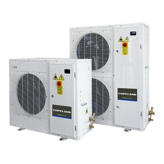
- Page 1 APPLICATION GUIDELINES Copeland outdoor refrigeration units for A2L & A1 applications ZXMY-020E to ZXMY-075E ZXDY-030E to ZXDY-075E ZXLY-020E to ZXLY-075E...
-
Page 2: Table Of Contents
Icon explanation....................1 Safety statements ....................2 General instructions ..................... 2 Product description....................3 General information about Copeland ZX*Y refrigeration units ......3 EU Ecodesign Directive 2009/125/EC..............3 Main product features and dimensions..............4 Product nameplate....................6 Nomenclature ...................... 6 Application range .................... - Page 3 2.16 Reset to factory settings – Copeland Controls Hot Key........27 2.16.1 How to save factory settings or user settings ..........27 2.16.2 Copeland Controls Hot Key for ZX*Y units with XCM25D controller.... 27 2.16.3 Location of the Hot Key plug connection on the XCM25D controller ... 27 2.16.4 How to program a hot key from the controller (upload)........
- Page 4 3.3.1 Power supply connections ................34 3.3.2 Maximum operating currents for cable selection ......... 36 3.3.3 Electrical protection standard (protection class) .......... 36 3.3.4 Terminal box....................36 3.3.5 Low-pressure protection ................37 3.3.6 Crankcase heater ..................37 3.3.7 Insulation material..................37 3.3.8 Vibration .....................
- Page 5 5.11 Condenser fans & motors .................. 50 Certification & approval ..................51 Dismantling & disposal ................... 51 Appendix 1: Overview of the ZX*Y unit components ............52 Appendix 2: Wiring diagram – ZXMY & ZXLY units (380-420 V / 3 Ph / 50 Hz)....53 Appendix 3: Wiring diagram –...
-
Page 6: About These Guidelines
About these guidelines The purpose of these application guidelines is to provide guidance in the application of Copeland ZX*Y outdoor refrigeration units. They are intended to answer the questions raised while designing, assembling and operating a system with these products. -
Page 7: Safety Statements
Safety statements ▪ Refrigerant compressors and refrigeration units must be employed only for their intended use. The system has to be labelled according to the applicable standards and legislation. ▪ Only qualified and authorized RACHP (refrigeration, air conditioning and heat pump) personnel are permitted to install, commission and maintain this equipment. -
Page 8: Product Description
Copeland has developed the ZX*Y outdoor refrigeration unit to meet primarily the demands of the food retail and food service sectors. It is a refrigeration air-cooled refrigeration unit that uses the latest Copeland patented scroll technology as the main driver and has electronic protection and diagnostics features built in the compact chassis. -
Page 9: Main Product Features And Dimensions
Main product features and dimensions Copeland ZX*Y refrigeration units are released for multiple refrigerants. They are available in two cabinet sizes and are equipped with one or two fans. These units are designed for medium- and low-temperature refrigeration applications. Displacement... -
Page 10: Figure 1: Dimensions Of Models Zxmy-020E To Zxmy-040E, Zxdy-030E And Zxly-020E To Zxly-040E (Single-Fan Units)
The figures hereafter show the overall physical dimensions of the ZX*Y refrigeration units in millimetres: Figure 1: Dimensions of models ZXMY-020E to ZXMY-040E, ZXDY-030E and ZXLY-020E to ZXLY-040E (single-fan units) Figure 2: Dimensions of models ZXMY-050E to ZXMY-075E, ZXDY-040E to ZXDY-075E and ZXLY-050E... -
Page 11: Product Nameplate
NOTE: R513A, R134a, R448A, R449A, R404A, R450A, R507A, R407C, R407A and R407F are classified as A1 refrigerants. In order to apply these refrigerants, the approval of the Application Engineering department at Copeland is required. NOTE: Some unit models are equipped with an oil separator – see section 2.7 "2.7BOM variations". -
Page 12: Ped Category
The BOM (bill of material) number at the end of the unit designation indicates the different unit layouts and details. The ZX*Y units covered in these guidelines are available in the following BOM versions: Introduction Suction Family Controller concept date separator accumulator ZXMY-020E to 10/2020 ZXMY-060E ZXMY-075E 10/2020 ZXDY-030E to XCM25D 10/2020 ZXDY-060E... -
Page 13: P&I Diagrams
2.8.1 ZXMY units Figure 4: P&I diagram for ZXMY units Fast access Position Description Comments menu High-efficiency Copeland scroll compressor Service valve, liquid line Service valve, suction line Condenser with 1 or 2 fans Liquid receiver Filter-dryer Sight glass 8 (PT) -
Page 14: Zxdy Units
2.8.2 ZXDY units Figure 5: P&I diagram for ZXDY units Fast access Position Description Comments menu High-efficiency Copeland scroll compressor (YBD* for digital) Service valve, liquid line Service valve, suction line Digital solenoid Y1 Pre-charged with 0.5 Oil separator Condenser with 1 or 2 fans... -
Page 15: Zxly Units
2.8.3 ZXLY units Figure 6: P&I diagram for ZXLY units Fast access Position Description Comments menu High-efficiency Copeland scroll compressor Service valve, liquid line Service valve, suction line Suction accumulator Oil separator Pre-charged with 0.5 l Condenser with 1 or 2 fans... -
Page 16: Main Components Description
Main components description 2.9.1 Compressor Medium temperature Low temperature Unit model Compressor model Unit model Compressor model Standard ZXMY-020E YB12K1E-TFM/TFD ZXLY-020E YF05K1E-TFD ZXMY-030E YB17K1E-TFM/TFD ZXLY-030E YF07K1E-TFD ZXMY-040E YB24K1E-TFM/TFD ZXLY-040E YF10K1E-TFD ZXMY-050E YB31K1E-TFM/TFD ZXLY-050E YF13K1E-TFD ZXMY-060E YB36K1E-TFM/TFD ZXLY-060E YF15K1E-TFD ZXMY-075E YB45K1E-TFM/TFD... -
Page 17: Xcm25D Electronic Controller - Features
NOTE: For detailed information about unit components and spare parts, please refer to the compressor application guidelines and to the Copeland Spare Parts Catalogue available at www.copeland.com/en-gb. XCM25D Electronic controller – Features 2.10 The XCM25D controller is designed to be a powerful, flexible controller for use in multiple applications. It has been developed for refrigeration units and allows the adjustment of all relevant parameters by the user. -
Page 18: Modbus Communication
The XCM25D controller can communicate via Modbus (RS-485) connection to provide all running data. Additional commands can also be activated through Modbus connection. The Modbus map is available on request from the Application Engineering department at Copeland. A pre-configured X-Web Supervisor device is also available and allows easy handling and connectivity with the XCM25D controller. -
Page 19: Additional Features For Customization
Motor current overload protection: This feature eliminates the need for external current protection for the compressor motor. Fixed high-pressure switch: This is a non-adjustable protection device designed to prevent the compressor from operating outside of its safe high-pressure range. Reset is automatic for a set number of trips (7) then the unit will lock out and require manual restart. -
Page 20: Table 12: Digital Output Specifications
Figure 11: Pre-arranged additional connections NOTE: Depending on the required functionalities additional components might be necessary. Please contact your local Application Engineering representative. NOTE: Check the current limitations given by the controller relays. NOTE: The solenoid valve function is not available on ZXDY units. Digital output Specifications DO1, DO2 and DO3... -
Page 21: Table 14: External Temperature Sensor - Parameters
Temperature control by means of an external temperature probe (not recommended for ZXDY units) The temperature of a cold room or cooling cabinet can be controlled by means of an additional temperature (Analog Input AI7, component B7 in wiring diagram) probe (NTC, 10 kΩ – for detailed temperature/resistance curve, see Appendix 7). - Page 22 Low ambient operation Very low ambient temperatures can result in malfunction of expansion devices because of insufficient pressure difference. Therefore, pressure cut-out during system start-up can occur. For proper operation of the expansion devices, the unit running time must allow to build up sufficient condensing pressure. At low ambient conditions, the compressor will need to run for a minimum period of time to allow the system pressures to stabilize.
-
Page 23: Table 16: Defrost Parameters
Factory settings / Parameter Description Recommended settings / Comments Range Workday defrost 00:00 – 23:50 or nu = Not used 00:00 start 1 Workday defrost 00:00 – 23:50 or nu = Not used 04:00 start 2 Workday defrost 00:00 – 23:50 or nu = Not used 08:00 start 3 Workday... -
Page 24: Xcm25D Electronic Controller - Programming
Manual defrost Please check settings for evaporator fans. The XCM25D controller can also control the evaporator fans during manual defrost. NOTE: For additional features please contact your local Application Engineering representative. XCM25D Electronic controller – Programming 2.11 CAUTION refrigerant charge! Compressor damage! Never energize... -
Page 25: Remote Display Ccm60
When front-mounted, the remote display is IP65 rated. Figure 14: Remote display front panel mounting The remote display is a proprietary bus of communication for Copeland Controls HMI (x-rep, CCM60) interfaces. There are two connection terminals on the back of the remote display (+ and -). -
Page 26: Double Commands - Entering Programming Level 1 "Pr1
2.11.4 Double commands – Entering programming level 1 "Pr1" Press simultaneously for about 3 seconds to lock (PoF) or unlock (Pon) the keyboard. Press simultaneously to leave the programming mode or menu. On submenus rtC and EEV this combination allows to go back to the previous level. Press simultaneously for about 3 seconds to access the first level of programming mode. -
Page 27: Fast Access Menu
2.11.7 Fast access menu The fast access menu contains the list of probes and some values that are automatically evaluated by the board such as the superheat and the percentage of valve opening. "nP" or "noP" stands for "Probe not present" or "Value not evaluated". "Err" means "Value out of range" or "Probe damaged, not connected or incorrectly configured". -
Page 28: Parameters Level 1 - Required Settings
Table 23: Parameters in programming level Pr1 NOTE: The full list of parameters in programming level "2" can be found in Technical Information TI_Unit_ZX_A2L_01 "Copeland ZX*Y outdoor refrigeration units for A1 & A2L applications – XCM25D Controller Parameter List". Digital operation 2.14... -
Page 29: Pumpdown
capacity according to the proportional band. If the pressure is lower than (C16-C17/2) the digital compressor switches off. Figure 16: Digital operation NOTE: When the digital valve on the compressor is discharged the compressor is loaded. NOTE: At start-up the valve is energized for C20 start-up time, ie, time interval with the digital valve energized before regulation starts. -
Page 30: Pumpdown With Room Thermostat (Not Available On Zxdy Units)
Operation of the unit below the suction pressures shown in the table could result in tripping of the compressor internal motor protector (Klixon, error code E28). The envelopes are in accordance with Select software available at www.copeland.com/en-gb/tools-resources. Unit family R454A... -
Page 31: Table 27: Internal Pumpdown With Temperature Sensor
temperature setpoint is defined by parameter G02. Adjust the temperature range with positive differential value G03. Figure 17: Pumpdown functionality with temperature sensor If the temperature increases and reaches setpoint plus differential, the liquid line solenoid output relay will energize the coil to open the valve. The compressor will be controlled by suction pressure. The temperature value is to be set between parameters G04 and G05. -
Page 32: Reset To Factory Settings - Copeland Controls Hot Key
There is no way to reset the XCM25D controller to factory settings other than with additional equipment. Copeland recommends using the Copeland Hot Key (not part of the standard delivery) to save the factory settings at initial power up. The same hot key can also be used to save user settings. -
Page 33: Troubleshooting - Alarm History
Troubleshooting – Alarm history 2.17 The controller records the total number of alarm activations (max 50) in the alarm menu – see Appendix 5. Action Key or display Notes Enter menu Push and release the ALR key. The menu to change the section will be entered. The alarm list Waiting for action section is active. -
Page 34: Other Inputs Of The Xcm25D Controller
Other inputs of the XCM25D controller 2.20 2.20.1 Customer-supplied control (room thermostat) The XCM25D electronic controller uses a digital input (DI3) open/close signal (such as the switching action of a normal commercial thermostat) and relays a similar action as an output to the compressor contactor in the case of a thermostat-controlled (parameter C05) system –... -
Page 35: Installation
The installation location must be selected in accordance with local workplace safety regulations. Copeland ZX*Y refrigeration units are delivered with a holding charge of neutral gas. The refrigeration unit should be located in such a place to prevent any dirt, dust, plastic bag, leaves or papers from covering the condenser and its fins. -
Page 36: Refrigeration Piping Connections
Suction line Liquid line Unit (ODS) (IDS) ZXMY-020E & ZXMY-030E ZXDY-030E 3/4" (19.05 mm) 1/2" (12.7 mm) ZXLY-020E & ZXLY-030E ZXMY-040E to ZXMY-075E ZXDY-040E to ZXDY-075E 7/8"... -
Page 37: Brazing Recommendations
3.2.2 Brazing recommendations WARNING Air/flammable refrigerant mixture! Creation of a potentially flammable atmosphere! Fire hazard! Remove all refrigerant before opening the system. When working on a refrigerant-filled system, make sure to follow the safety and working instructions given in Chapter 5 "Maintenance & repair". WARNING High temperature! Burning! Proceed with caution when brazing system components. -
Page 38: Brazing Procedure
3.2.3 Brazing procedure WARNING Air/A2L refrigerant mixture! Fire hazard! For systems using flammable A2L refrigerant, it is mandatory to flush oxygen-free nitrogen through the piping during the brazing process. Brazing must be carried out in compliance with ISO 14903. Refer to Figure 22 and procedure below for the brazing of the tubes: ▪... -
Page 39: Power Supply Connections
DIN EN 60204-1. Additionally, the voltage drop and line temperatures must be considered for cable selection. Copeland ZX*Y refrigeration units are designed for 380-420 V / 3 Ph / 50 Hz power supply. A voltage tolerance of ± 10 % is acceptable. -
Page 40: Figure 26: Ground Connection On Door
Figure 26: Ground connection on door Figure 27: Ground connection on condenser Figure 28: Ground connection in electrical cabinet AGL_Unit_ZX_A2L_A1_EN_Rev01... -
Page 41: Maximum Operating Currents For Cable Selection
3.3.2 Maximum operating currents for cable selection Unit model Locked rotor Rated current Medium temperature standard units ZXMY-020E-TFM/TFD 26.0 A 5.21 A ZXMY-030E-TFM/TFD 32.0 A 6.51 A ZXMY-040E-TFM/TFD 50.0 A 8.81 A ZXMY-050E-TFM/TFD 64.0 A 11.62 A ZXMY-060E-TFM/TFD 74.0 A 13.32 A... -
Page 42: Low-Pressure Protection
Internal arcing! Motor destruction! Do not perform high-voltage or insulation tests if the compressor housing is under vacuum. Copeland subjects all units to a high-voltage test after final assembly. Each unit is tested according to EN 60034-1 at a differential voltage of 1000 V plus twice the nominal voltage. -
Page 43: Circuit Breaker With Overcurrent Protection
Figure 29: Circuit breaker with overcurrent protection Refrigeration units Medium temperature Low temperature Standard Setting Digital Setting Standard Setting ZXMY-020E 4.1 A ZXLY-020E 5.0 A ZXMY-030E 5.2 A ZXDY-030E 7.3 A ZXLY-030E 6.0 A ZXMY-040E 7.3 A... -
Page 44: Pressure Relief Valve (Prv)
Pressure relief valve (PRV) To meet the damage limitation requirements in the event of an external fire, a pressure relief valve should be fitted on the ZX*Y refrigeration unit using the dedicated 3/8" NPT connection port. Make sure to select a PRV that is qualified for this purpose and application. -
Page 45: Location & Fixings
Connect the discharge pipe to the PRV outlet and lead the discharge pipe to the outside of the refrigeration unit – see example in Figure 33 below. If needed, fix the discharge pipe to avoid vibrations. PRV discharge pipe requirements: ▪... -
Page 46: Figure 35: Fixing Dimensions And Distances - Dual-Fan Units
Figure 35: Fixing dimensions and distances – Dual-fan units Ideally, the unit should be mounted level on a solid concrete slab with anti-vibration pads between unit feet and concrete. However, the ZX*Y refrigeration unit has also been designed for wall mounting on suitable brackets. -
Page 47: Start-Up & Operation
Start-up & operation WARNING Diesel effect! System explosion! The mixture of air and oil at high temperature can lead to an explosion. Avoid operating with air. WARNING Air/flammable refrigerant mixture! Creation of a flammable atmosphere! Make sure the atmosphere is non-flammable before starting the system. Ensure that the system contains only refrigerant and there is no flammable gas in the ambient. -
Page 48: Charging Procedure
Charging procedure 4.4.1 Refrigerant charging procedure WARNING Air/A2L refrigerant mixture in a potentially flammable atmosphere! Fire hazard! Only use filling equipment designed and approved for use and operation with A2L refrigerant. Make sure all connections are tight to avoid leakage. Make sure to fill with pure A2L refrigerant. -
Page 49: Oil Charging Procedure
4.4.2 Oil charging procedure Copeland ZX*Y refrigeration units are pre-charged with oil. After commissioning, the oil level should be checked and topped up if necessary. As mentioned in section 2.6.1 "Qualified refrigerants and oils", Copeland recommends charging with one of the following oil types: ▪... -
Page 50: Pressure Fluctuations In Case Of Digital Unit
The system pressure shall not be allowed to go down below the pressure values shown in section 2.10.4 "Main control & safety features". If this happens, immediately stop the unit and/or de-energize the power supply of the unit. Please also refer to the application envelopes which can be found in Select software, available at www.copeland.com/en-gb. AGL_Unit_ZX_A2L_A1_EN_Rev01... -
Page 51: Maintenance & Repair
Maintenance & repair General considerations WARNING Conductor cables! Electrical shock hazard! Follow the lockout/tag out procedure and the national regulations before undertaking any maintenance or service work on the system. Screwed electrical connections must be used in all applications. Refer to original equipment wiring diagrams. -
Page 52: Disassembling System Components
Disassembling system components When disassembling system components the recommendations below shall be followed: ▪ Recover refrigerant and evacuate system using an A2L-dedicated recovery unit and vacuum pump. All the refrigerant shall be recovered to avoid significant release. Ensure that the outlet of the vacuum pump is not close to any potential ignition source and that ventilation is available. -
Page 53: Exchanging The Refrigerant
NOTE: Please refer to the Copeland spare parts catalogue available at www.copeland.com/en- gb/tools-resources to select the correct crankcase heater model. -
Page 54: Electrical Terminations
As a general rule and for a clean environment Copeland recommends that the fins be cleaned with liquid detergent diluted with clean water. The ZX*Y unit has a well-designed chassis with levels sloping towards a large drainage hole and provided the unit is installed level, any cleaning solution should be able to drain away. -
Page 55: Condenser Fans & Motors
Condenser fans & motors 5.11 A yearly inspection of these items is recommended. Fastenings can become loose, bearings may wear and fans may require cleaning of solid deposits that can cause rotational imbalance. Motors come with lifelong lubrication bearings that do not require lubricating on a routine basis, but just need to be checked for wear. -
Page 56: Certification & Approval
− EN 61000-6-3: Electromagnetic compatibility (EMC) Part 6-3: Generic standards – Emission standard for residential, commercial and light-industrial environments. ▪ The Copeland ZX*Y refrigeration units and their piping comply with the Pressure Equipment Directive PED 2014/68/EU. Applied harmonized standards: − EN 378-2: Refrigerating systems and heat pumps – Safety and environmental requirements Part 2: Design, construction, testing, marking and documentation. -
Page 57: Appendix 1: Overview Of The Zx*Y Unit Components
Appendix 1: Overview of the ZX*Y unit components Medium temperature Low temperature Components Standard Digital Standard ZXMY ZXDY ZXLY Compressor M1 Fan M2.1 ZXMY-050E – ZXMY-075E ZXDY-050E – ZXDY-075E ZXLY-050E – ZXLY-075E Fan M2.2 Y1 Stepper valve EVI Not used Not used... -
Page 58: Appendix 2: Wiring Diagram - Zxmy & Zxly Units (380-420 V / 3 Ph / 50 Hz)
Appendix 2: Wiring diagram – ZXMY & ZXLY units (380-420 V / 3 Ph / 50 Hz) Figure 43: Wiring diagram – ZXMY & ZXLY units AGL_Unit_ZX_A2L_A1_EN_Rev01... -
Page 59: Appendix 3: Wiring Diagram - Zxdy Units (380-420 V / 3 Ph / 50 Hz)
Appendix 3: Wiring diagram – ZXDY units (380-420 V / 3 Ph / 50 Hz) Figure 44: Wiring diagram – ZXDY units AGL_Unit_ZX_A2L_A1_EN_Rev01... -
Page 60: Appendix 4: Parameters Level 1
Appendix 4: Parameters level 1 Legend L1 = Parameter in level 1 (without password) L2 = Parameter in level 2 (with password = 3 2 1) N.V. = Parameter not accessible NOTE: When changing parameters C01, C02 and C05 a reset of the controller (interruption of power supply) is required. Parameter Description Range... -
Page 61: Appendix 5: Alarm Menu
Appendix 5: Alarm menu Code Description Cause Action Reset Only in digital units – Compressor AI1 error (Probe 1 / Suction activated according to C23; compressor Automatically as soon as the probe restarts Probe failure or out of range pressure transducer failure alarm) on &... - Page 62 Code Description Cause Action Reset Manual power off, invert 2 phases and power on. Incorrect phase sequence The compressor will lock out, rotation If the phase sequence is correct but the controller Phase sequence lockout (3-phase units) field has to be changed still shows the error message, set parameter H25 to "No".
- Page 63 Code Description Cause Action Reset Automatically: as soon as electrical current is Compressor built-in thermal High motor temperature Warning signal only detected. Check the voltage coming to the protector trip compressor. Main power lost Controller power supply lost Automatically: high-pressure switch closed and D14 delay elapsed.
-
Page 64: Table 37: Alarm Code Overview
Code Description Cause Action Reset Max pressure alarm of superheating Not used Min pressure alarm of superheating Not used High superheating alarm Not used Low superheating alarm Not used High room temperature alarm Not used Low room temperature alarm Not used Warning signal only if G09 = "no";... -
Page 65: Appendix 6: Additional Features For Customization
Appendix 6: Additional features for customization Required setting for proper functionality Setting needs to be adjusted according to application Room thermostat or pressure switch (not available on ZXDY units) System restart is required! Parameter Parameter description Factory setting Required setting Compressor regulation probe selection SuP = Suction pressure probe dIS = Suction pressure switch / Room thermostat... - Page 66 Pumpdown with temperature sensor in case temperature (not available on ZXDY units) System restart is required! Parameter Parameter description Factory setting Required setting Probe 7 configuration nu = Not used tnt = Thermostat temperature Compressor regulation probe selection SuP = Suction pressure probe CSt = Case temperature Case temperature probe selection nu = Not used...
- Page 67 1 min Adjust to application requirements Technical Information TI_Unit_ZX_A2L_01 G28-41 "Copeland ZX*Y outdoor refrigeration units for A1 & A2L Adjust to application requirements Applications – XCM25D Controller parameter list" Defrost with evaporator fan System restart is required! Parameter Parameter description...
-
Page 68: Table 38: Additional Features For Customization
Evaporator fan System restart is required! Parameter Parameter description Factory setting Required setting cn = Switch on and off with the compressor, stop during defrost On = Always on, stop during defrost Fans operating mode cy = Switch on and off with the compressor, run during defrost Oy = Always on, run during defrost Relay output 2... -
Page 69: Appendix 7: Temperature / Resistance Curve For B7 Sensor (Customer Option)
Appendix 7: Temperature / resistance curve for B7 Sensor (customer option) R25 = 10 kΩ B25/85 = 3435 K Temp. Resistance Temp. Resistance Temp. Resistance Temp. Resistance Temp. Resistance Temp. Resistance (kΩ) (kΩ) (kΩ) (kΩ) (kΩ) (kΩ) ( C) ( C) ( C) ( C) ( C) -
Page 70: Appendix 8: List Of Tables And Figures
Table 39: B7 AI7 optional sensor >> Temperature / resistance curve ............. 64 Figures Figure 1: Dimensions of models ZXMY-020E to ZXMY-040E, ZXDY-030E and ZXLY-020E to ZXLY-040E (single-fan units)............................5 Figure 2: Dimensions of models ZXMY-050E to ZXMY-075E, ZXDY-040E to ZXDY-075E and ZXLY-050E to ZXLY-075E (dual-fan units)........................ - Page 71 Figure 44: Wiring diagram – ZXDY units....................54 DISCLAIMER: The Copeland logo is a trademark and service mark of Copeland LP or one of its affiliates. Copeland Europe GmbH shall not be liable for errors in the stated capacities, dimensions, etc., as well as typographic errors. Products, specifications, assumptions, designs and technical data contained in this document are subject to modification by us without prior notice.
- Page 72 Tel. +49 (0) 2408 929 0 - Fax: +49 (0) 2408 929 570 – Internet: copeland.com/en-gb The Copeland logo is a trademark and service mark of Copeland LP or one of its affliates. Copeland Europe GmbH shall not be liable for errors in the stated capacities, dimensions, etc., as well as typographic errors.
Need help?
Do you have a question about the ZXMY-020E and is the answer not in the manual?
Questions and answers