
Summary of Contents for Vimpex Hydrosense
-
Page 1: Table Of Contents
Hydrosense Overview of the Hydrosense Water Detection System Linear Detection Point Detection Components of a Hydrosense System Hydrosense Mimic Panels Design & Planning Design Guidelines System Installation Notes Hydrowire Installation and Commissioning Hydrowire Commissioning – HSHWC-100 Floor Probe or Drip Tray Probe Installation HSFPI -100... -
Page 2: Overview Of The Hydrosense Water Detection System
Hydrosense Overview of the Hydrosense Water Detection System The Hydrosense water detection system is designed to detect the intrusion of water in concealed areas or any place where water penetration must be identified so that corrective action can be taken immediately. -
Page 3: Linear Detection
Hydrosense Linear Detection Where floor areas, ducts and suspended ceilings need to be protected this is usually best achieved by installing lengths of Hydrowire. Hydrowire is a highly conductive cable extremely sensitive to moisture. It is available in 5 metre lengths (K2104) or 10 metre lengths (K2105). Each... -
Page 4: Components Of A Hydrosense System
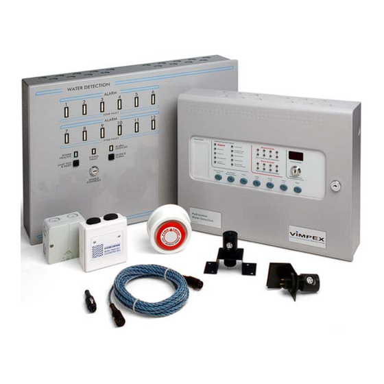
Hydrosense Components of a Hydrosense System This guide will help to select products from the Hydrosense range for water detection in a variety of applications. Basic Components Control Panel (2 to 48 Zones) There are two types of control panel available: a) HSCP Series –... -
Page 5: Hydrosense Mimic Panels
Hydrosense Hydrosense Mimic Panels The Hydrosense Mimic Display uses flexible fibre optic guides to illuminate areas on a floor plan. This provides a clear, geographical indication of the alarm activation enabling a speedy identification of the source and location of the alarm. - Page 6 Hydrosense The following components are common to both panels: Hydrowire (5 metre Length) K2104 Hydrowire (10 metre Length) K2105 End of Line Plug K2110 Hydrowire Connection Box K2106 Leader Cable K2111 Hydrowire / Leader Cable Fixing Clips K2112 Batteries K1220...
-
Page 7: Design & Planning
Will the system require expansion? Give consideration to the possible addition of extra zones. Maximum length of Hydrosense cable should be kept to 50 metres Maximum number of detectors per zone should not exceed 20. Only one remote indicator to each Hydrowire Connection Box. -
Page 8: Design Guidelines
Hydrosense Design Guidelines Hydrosense Probe: Maximum recommended coverage: 20 sq.m per detector Maximum recommended detectors per zone Maximum distance between probes for perimeter detection 3 metres Sensor height above finished floor 1mm to 15mm Leader cable 0.75mm round 3A... -
Page 9: System Installation Notes
Hydrosense System Installation Notes 1. Check design with the kit and components in hand to check that all materials are on site. Check the BOM. 2. Store Hydrowire lengths carefully in a dry area. 3. Prepare the installation area. Remove any furniture or equipment that may obstruct installation. -
Page 10: Hydrowire Installation And Commissioning
Hydrosense Hydrowire Installation and Commissioning HYDROWIRE INSTALLATION HSHWI-100 (1) Check the length of cable for fraying or damage. (2) Connect the lengths of Hydrowire to be used in the zone and terminate with an End of Line Plug (K2110). Temporarily connect the cable to the control panel via a Hydrowire Connection Box (K2106). -
Page 11: Hydrowire Commissioning - Hshwc-100
Hydrosense (9) Plug the cable into the Hydrowire Connection Box (K2106). (10) The red warning label should be left such that it is clearly visible. (11) Terminate the cable with an end of line plug (K2110). Notes : Hydrowire should not come into contact with surface temperatures greater than 70 Lengths greater than 50 metres are not permissible. -
Page 12: Floor Probe Or Drip Tray Probe Installation Hsfpi -100
Hydrosense Floor Probe or Drip Tray Probe Installation HSFPI -100 The floor probe is connected to the control panel via a junction box (See Fig. 11). Note: The 6K8 resistor taken from the zone being used in the control panel must be installed as shown in Fig. 1 with the last Probe in the zone (maximum of 20 probes per zone.) -
Page 13: Floor Or Drip Tray Probe Testing
Hydrosense Floor or Drip Tray Probe Testing (1) This is best achieved by dipping the tips of the probe pins into a cup of tap water. (2) This should produce an immediate reaction at the control panel, the LED mounted on top of the probe and, if fitted, the remote lamp unit and or sounder. -
Page 14: Hydrowire Connection Box
Hydrosense Hydrowire Connection Box The K2106 Connection Box, when triggered presents an impedance of 470 ohms to the 24 Volt circuit from the control panel. Hydrowire Connection Box The + and – terminals inside the Connection Box must be connected via a 2 wire 0.75mm round 3A cable to the Z+... -
Page 15: Hydrosense Commissioning Record
Hydrosense Hydrosense Commissioning Record Customer / Site Address Town / City Post Code Site Tel No. Site Contact Name Control Panel Type No. of Hydrowire Zones No. of Probe Zones Authorised Engineer Company Tel No. Date Control Panel Control panel is connected via a dedicated power supply Green Supply Healthy lamp illuminated. - Page 16 Hydrosense Hydrosense Commissioning Record Connection Boxes Installed Not Installed Fixed securely Wiring terminated correctly Floor and Drip Tray Probes Installed Not Installed Din plug disconnected from probe and checked for correct zone fault Probe conductor pins set at correct height...
-
Page 17: Hydrowire Layout
Figure 3 Hydrosense Hydrowire Layout Part Ref Description HSCP-S-4 4 HSCP Panel K2105 Hydrowire 10M Length K2110 End of Line Plug K2106 Connection Box K2112 Pack of Fixing Clips K2101 Floor Mounted Probe K/Z/Box1 ABS Junction Box for Probes *PS1270 12V 2.0ah Battery... -
Page 18: Probe Layout
Hydrosense Figure 4 Probe Layout www.acornfiresecurity.com... -
Page 19: Consultants Specification For Water Leak Detection
Hydrosense CONSULTANTS SPECIFICATION FOR WATER LEAK DETECTION The water detection system should be able to detect the intrusion of water in concealed areas or any place where water penetration must be identified so that corrective action can be taken immediately.
Need help?
Do you have a question about the Hydrosense and is the answer not in the manual?
Questions and answers