
Summary of Contents for Q-NEX NPS100
- Page 1 NEX Networked Presentation Switcher NPS100 —— User Manual —— Returnstar Interactive Technology Group Co., Ltd.
-
Page 2: Table Of Contents
Content 1. Introduction ................................2 2. Components of NPS100 ............................2 2.1 NPS100 Front View ............................3 2.2 NPS100 Rear View ............................3 3. Wiring and setup ..............................4 3.1 Get Ready for NPS100 ............................4 3.2 Presentation Switch ............................7 3.3 Audio Control ............................... 11 3.4 Device Control Settings .......................... -
Page 3: Introduction
We are committed to providing you with assistance. Thank you for choosing the Q-NEX NPS100, and may each of your meetings be characterized by convenience and efficiency. -
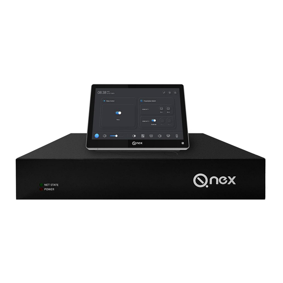
Page 4: Nps100 Front View
- Blinking: Indicates that the device is engaged in network communication. - Off: Indicates that the device is offline and unable to connect to the network. POWER Power Status Indicator Light: This light indicates the normality of the NPS100 device's power. 2.2 NPS100 Rear View... -
Page 5: Wiring And Setup
3.1.1 Powering On and Connecting to the Network 1. Power On:Connect power to the NPS100, then turn on the switch. When you hear a beep, it indicates that the device is booting up, and the red power indicator light will illuminate. - Page 6 Select 'Devices >> Processor Manage,' and then click 'Add Device.' On the 'Add Device' page, enter the device name (e.g., Meeting Room 1) and device ID (NPS100 product S/N). Choose a group. In the Startup Options, select device parameters based on the actual situation.
- Page 7 Connect the Touch Panel to the NPS100 LAN port. – Connect the Touch Panel to the router/switch, ensuring the Touch Panel and NPS100 are on the same LAN. Enter IP Address: After connecting to the network, input the NPS IP address on the Touch Panel.
-
Page 8: Presentation Switch
:As pictured above, retrieve the NPS IP address from the 'Devices >> Processor Manage' page. Input this address on the Touch Panel and click 'Connect.'". :If connection issues arise, use the router device or NPS config Tool.exe to identify the correct IP address, particularly in situations where DHCP changes may not be immediately reflected in the web- based backend. - Page 9 'Presentation Switch. When 'Duplicate' to the right of HDMI OUT2 is disabled: NPS100 is in normal HDMI matrix switching mode, allowing source switching on different HDMI OUT output devices through the Touch Panel. When 'Duplicate' to the right of HDMI OUT2 is enabled: HDMI OUT1 can switch sources, while HDMI OUT2 will duplicate the content displayed on HDMI OUT1.
- Page 10 PC1 to access all USB Device devices connected to "USB Device". The same applies when IQTouch A switches to PC2. Operations can also be performed on the Web-Console, as shown in the image: 3.2.3 USB Devices Connection USB Interfaces NPS100 provides 2 USB Host interfaces and 4 USB Device interfaces.
- Page 11 USB HOST USB Host corresponds to the HDMI IN input device. For example: Connect HDMI and USB from the same PC to NPS100. USB Devices Four USB Devices can be connected to microphones, keyboards and mice, PTZ cameras, USB flash drives, IFP, etc.
-
Page 12: Audio Control
USB Device can only be accessed by the PC when it is the input source for that display device. 3.3 Audio Control NPS100 provides an Audio IN and an Audio Out interface. Audio IN: Connect external audio devices, such as microphones. - Page 13 Operations on the sound amplification device can be performed through the Web-console platform, as shown in the figure: At the same time, you can select the option with the Q-NEX name on your PC to invoke the meeting room's speaker, as shown below:...
-
Page 14: Device Control Settings
3.4 Device Control Settings 3.4.1 Relay control NPS100 provides a Relay interface, allowing users to control various devices, such as lamps, electric curtains, etc. The following is an illustration using lighting control: Wago interface cable preparation: Step Screenshot Instructions 1. Uncovered copper wire length>=10mm 2. - Page 15 Implementing lighting control There are two methods to achieve lighting control with NPS via Relay interface: direct connection and integration with an SPDT switch. 2.1 Direct Connection to NPS: In this mode, the user gains the ability to manage the lighting control by NPS. :The current-carrying capacity of the“Relay”...
- Page 16 :The current-carrying capacity of the“Relay” should not exceed 1200W Warning: During installation, please ensure not to simultaneously connect the neutral and live wires of the AC power (or positive and negative terminals of DC power) to the Relay port. Failure to comply may result in a short circuit.
- Page 17 3.4.2 IR Control(NPS) The NPS100 is equipped with both an IR IN and an IR OUT interface, allowing users to manage IR devices efficiently. To control IR-enabled devices like air conditioners, TVs, projectors, etc. It allows batch application of infrared control codes to identical devices, Identified / learned IR codes can be applied to multiple Networked Presentation Switchers without the need for repetitive learning.
- Page 18 Follow these steps: Step Screenshot Instructions On the IR control page, click “Identify New A/C control code" Click the "Start" button Align the remote control with the IR interface, press the power button, and the system will automatically identify the remote control code.
- Page 19 Upon successful identification, it will display " Identify successfully." After identification, enter the air conditioner's brand and category, then click Save. You will be redirected to the IR Control Setting page. Select the newly added air conditioner name and click Save.
- Page 20 Log in to the "Q-NEX console -> Dashboard -> Devices -> Processor manager". Select your NPS device, and in the "Infrared Control" module, click the "Edit" button. Follow the instructions below:...
- Page 21 In the IR control interface, click "New remote control code." button Select A/C click "Next". Click "Start to learn" 1. On the remote control, select the desired mode, such as setting the temperature to 25 degrees and choosing the cooling mode. 2.
- Page 22 After successful learning, a "Success" prompt will appear. Then click "Next" button Enter the corresponding function name here Then you will be redirected to the "IR Control Setting" page. Then, select the newly added function name and click Save. After successfully saving, you can operate the device on the Touch Panel:...
- Page 23 You can also operate it on the Web-Console. :To learn additional modes for the air conditioner, follow steps S1 through S7. Additionally, note that the process for learning codes on other infrared devices is similar to the above steps 3.4.4 RS232 Control NPS provides two RS232 interfaces, enabling control of devices such as IFP, projectors, and PTZ cameras.
- Page 24 The other end of the RS232 cable should be connected according to the instructions in the camera's manual. Log in to Q-NEX console -> Dashboard -> Devices -> Processor manager. Select your NPS device, and in the "RS232 Control" module, click the "Edit" button: On the RS232 page, choose the corresponding port (1 or 2), then select the device type as PTZ Camera .
- Page 25 Panel are set on the same LAN. And we highly recommend the model CV810 PTZ cam from IQ, which is compatible with NPS100 very well. In the Web-console, you can only control the power of the PTZ camera; control-related operations need...
-
Page 26: Contact Us
2006. Q-NEX is focused on delivering a Smart Campus Solution that converges AV and loT control across all campus facilities. Q-NEX offers deeply customized options that assist school IT administrators in managing all electronic facilities and allows teachers to simplify the operations of a multimedia classroom. - Page 27 www.QnexTech.com info@QnexTech.com 6th Bldg. High-Tech Base. Fuzhou Fujian Prov. China...
Need help?
Do you have a question about the NPS100 and is the answer not in the manual?
Questions and answers