Table of Contents
Advertisement
Quick Links
SERVICE MANUAL
Warning
The technical information and parts shown in this
manual are not to be used for: the development,
design, production, storage or use of nuclear, chemical,
biological or missile weapons or other weapons of
mass destruction; or military purposes; or purposes that
endanger global safety and peace. Moreover, do not
sell, give, or export these items, or grant permission for
use to parties with such objectives. Forward all inquiries
to Hitachi Ltd.
Be sure to read this manual before servicing. To assure safety from fi re, electric shock, injury, harmful
radiation and materials, various measures are provided in this Hitachi Multimedia LCD Projector. Be
sure to read cautionary items described in the manual to maintain safety before servicing.
1. When replacing the lamp, avoid burns to your fi ngers, the lamp becomes very hot.
2. Never touch the lamp bulb with a fi nger or anything else. Never drop it or give it a shock, they may
cause bursting of the bulb.
3. This projector is provided with a high voltage circuit for the lamp. Do not touch the electric parts of
power unit (circuit) and power unit (ballast), after turning on the projector.
4. Do not touch the exhaust fan during operation.
5. The LCD module assembly is likely to be damaged. If replacing the LCD LENS/PRISM assembly,
do not hold the FPC of the LCD module assembly.
6. Use the cables which are included with the projector or as specifi ed.
1. Features ----------------------------------------------- 2
2. Specifi cations ----------------------------------------- 2
3. Names of each part ---------------------------------3
4. Adjustment --------------------------------------------6
5. Troubleshooting ------------------------------------ 12
6. Service points -------------------------------------- 17
7. Wiring diagram ------------------------------------- 30
SPECIFICATIONS AND PARTS ARE SUBJECT TO CHANGE FOR IMPROVEMENT.
Multimedia LCD Projector
Caution
Service Warning
Contents
August 2005 Digital Media Division
SM0557
CP-S240WF
CP-X250WF
ED-X8250
8. Disassembly diagram ----------------------------- 37
9. Replacement parts list ---------------------------- 44
10.RS-232C commands ----------------------------- 46
11. Block diagram -------------------------------------- 55
12. Connector connection diagram ---------------- 56
13.Basic circuit diagram ------------------------------ 57
(CC9SM)
(CC9XM)
(CC9XM)
Advertisement
Table of Contents

Related Manuals for Hitachi CP-S240WF


Summary of Contents for Hitachi CP-S240WF
-
Page 1: Table Of Contents
Be sure to read this manual before servicing. To assure safety from fi re, electric shock, injury, harmful radiation and materials, various measures are provided in this Hitachi Multimedia LCD Projector. Be sure to read cautionary items described in the manual to maintain safety before servicing. -
Page 2: Features
CP-S240(CC9SM)/CP-X250(CC9XM) 1. Features • High Brightness • Low Noise • Rich Connectivity • Compact Body 2. Specifications CP-S240 CP-X250 Drive system TFT active matrix Liquid crystal Panel size 1.5cm(0.6 type) panel Number of pixels 800 (H) x 600 (V) 1024 (H) x 768 (V) Lamp 180W UHB Video : Analog 0.7Vp-p(75Ω... -
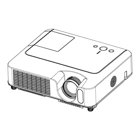
Page 3: Names Of Each Part
CP-S240(CC9SM)/CP-X250(CC9XM) 3. Names of each part ● Projector Control buttons Lamp cover Remote sensor (Lamp unit is inside.) Speaker Zoom knob Security bar Focus ring (Use for attaching a commercial anti-theft chain or wire.) Vent Elevator button Lens Front-Right side Elevator foot Lens cover Filter cover... - Page 4 CP-S240(CC9SM)/CP-X250(CC9XM) Power switch AC inlet Elevator button Ports (See below.) Elevator foot Rear-Left side Vent CONTROL port Restart switch (*) AUDIO-OUT port RGB IN1 port AUDIO IN2 L/R port RGB IN2 /RGB OUT port (In the default setting, the (Use the RGB IN OUT switch to select AUDIO IN2 L/R port is the audio RGB IN2 or RGB OUT for this port.) port for the VIDEO, S-VIDEO...
-
Page 5: Control Buttons
CP-S240(CC9SM)/CP-X250(CC9XM) Control buttons LAMP indicator TEMP indicator Cursor buttons POWER indicator ▲,▼,◄,► STANDBY/ON button INPUT button Remote control SEARCH button STANDBY/ON button RGB button AUTO button SEARCH VIDEO VIDEO button BLANK button ASPECT AUTO BLANK ASPECT button PAGE UP button MAGNIFY PAGE UP HOME button... -
Page 6: Adjustment
CP-S240(CC9SM)/CP-X250(CC9XM) 4. Adjustment 4-1 Before adjusting 4-1-1 Selection of adjustment When any parts in the table 4-1 are changed, choose the proper adjusting items with the chart. Table 4-1: Relation between the replaced part and adjustment Adjustment Replaced White Color Convergence Ghost Flicker... -
Page 7: Convergence Adjustment
CP-S240(CC9SM)/CP-X250(CC9XM) 4-2 Convergence adjustment Signal pattern for internal adjustment Perform this adjustments only when the conver- gence is not good. 1. Open FACTORY MENU and then select OPTION > CNV-V. Use R and/or B so that three colors of images can be converged at center, top and bottom of the screen. - Page 8 CP-S240(CC9SM)/CP-X250(CC9XM) 4-4 Flicker adjustment (V.COM adjustment) Adjustment procedure Signals for internal adjustment 1. Make this adjustment after completing the adjustment in 4-3 Ghost adjustment. 2. Use DAC-P - V.COM - R: in the FACTORY MENU to adjust so that the flicker at the center of the screen is less than the flicker at the periphery.
- Page 9 CP-S240(CC9SM)/CP-X250(CC9XM) 4-6 Color uniformity adjustment Preparations 1. Perform these adjustments after the white balance 6. To temporarily turn correction off, place the adjustment described in Section 4-5. cursor on [C.UNIF.] in the Adjust Tone menu and 2. Make a color uniformity adjustment for the follow- press the [ ] key.
- Page 10 CP-S240(CC9SM)/CP-X250(CC9XM) Adjustment procedure 1 (When a color differential meter is used) 1. First adjust [MID-L] tone [G:]. 9. Similarly, measure adjustment points [No.3] to 2. Select adjustment point [No.2][G:]. [No.17] and adjust their color coordinates start- When the background is not [G] monochrome, ing in order from the small number points.
- Page 11 CP-S240(CC9SM)/CP-X250(CC9XM) Adjustment procedure 2 (visual inspection) 1. First adjust [MIN] tone [G:]. 6. View measurement points [No.2], [No.3], 2. Select [No.2] [G:]. [No.10] and [No.11]. Adjust the [R] and [B] of If the background is [G] monochrome, press the each measurement point so that they have the [ENTER] key on the Remote control transmitter same color as measurement point [No.1].
-
Page 12: Troubleshooting
CP-S240(CC9SM)/CP-X250(CC9XM) 5. Troubleshooting Check points THERMAL SWITCH (TSW) E801 S801 IS14 IS01 IS13 E800 IS40 IS12 IS42 IS11 IS41 E301 IS10 E802 P501 P601 D303 D301 (LAMP) (POWER) E304 D302 (TEMP) P701 E807 PWB assembly MAIN E302 E806 EASP E805 PWB assembly REMOTE Speaker cable... - Page 13 CP-S240(CC9SM)/CP-X250(CC9XM) Power can not be turned on *: Be sure to unplug the power cord before measuring resistance. voltage Measure supplied at pins (6) resistance* between pins 0Ω and (8) of E800 on the PWB PWB assembly MAIN (6) and (10), and between assembly MAIN in pins (8) and (10) of standby mode?
- Page 14 CP-S240(CC9SM)/CP-X250(CC9XM) Lamp does not light *: Be sure to unplug the power cord before measuring resistance. What is the state of Blinks Light LAMP indicator D303 during operation? Is the Measure LAMP installation install the Lamp Open resistance* between correct? pins (1) and (2) of S801 Lamp door Not light...
- Page 15 CP-S240(CC9SM)/CP-X250(CC9XM) Picture is not displayed. Confirm the splash screen the LCD Panels CPC30 connector A/B and the user menu displayed connection to the MAIN correctly? board. PWB assembly MAIN LCD/Lens prism assembly Are all of the pictures from video, s-video and PWB assembly MAIN component video ports displayed correctly?
- Page 16 CP-S240(CC9SM)/CP-X250(CC9XM) No sound Check at operating mode (Make sure the state of MUTE and Volume) Disconnect the speaker from the infinity PWB assembly Main, and Speaker measure its resistance. about 8 PWB assembly Main Can not control to RS-232C The check after parts change 1.
-
Page 17: Service Points
CP-S240(CC9SM)/CP-X250(CC9XM) 6. Service points 6-1 Lead free solder [CAUTION] This product uses lead free solder (unleaded) to help preserve the environment. Please read these instructions before attempting any soldering work. CAUTION Always wear safety glasses to prevent fumes or molten solder from getting into the eyes. Lead free solder can splatter at high temperatures (600˚C). - Page 18 Therefore, regarding these parts, you can either replace part, LCD/Lens prism assembly, or send the whole unit LCD/Lens prism assembly back to HITACHI, where we will replace the malfunctioning part, recondition the device and send it back to you.
- Page 19 CP-S240(CC9SM)/CP-X250(CC9XM) 3. Maintenance point Swab Panel Each color part has same construction. By using swab and air duster, Holder you can easily remove dust from panel and optical filter. Optical filter Actual formation Separatied formation 4. Cleaning the panels and optical filters (1) Turn on the set and lit on the lamp.
-
Page 20: Putting Batteries
CP-S240(CC9SM)/CP-X250(CC9XM) 6-4 Putting batteries WARNING Always handle the batteries with care and use them only as directed. Improper use may result in battery explosion, cracking or leakage, which could result in fire, injury and/or pollution of the surrounding environ- ment. ●Be sure to use only the batteries specified. -
Page 21: Air Filter
CP-S240(CC9SM)/CP-X250(CC9XM) 6-5 Air filter WARNING • Before caring, make sure the power switch is off and the power cable is not plugged in, then allow the projector to cool suffi ciently. The care in a high temperature state of the projector could cause an electric shock, a burn and/or malfunction to the projector. - Page 22 CP-S240(CC9SM)/CP-X250(CC9XM) 6-6 Lamp WARNING HIGH VOLTAGE HIGH TEMPERATURE HIGH PRESSURE ● The projector uses a high-pressure mercury glass lamp. The lamp can break with a loud bang, or burn out, if jolted or scratched, handled while hot, or worn over time. Note that each lamp has a different life- time, and some may burst or burn out soon after you start using them.
-
Page 23: Replacing The Lamp
CP-S240(CC9SM)/CP-X250(CC9XM) Replacing the Lamp A lamp has a fi nite product life. Using the lamp for long periods of time could cause the pictures darker or the color tone poor. Note that each lamp has a different lifetime, and some may burst or burn out soon after being started using. -
Page 24: Other Care
CP-S240(CC9SM)/CP-X250(CC9XM) 6-7 Other care WARNING Before caring, make sure the power switch is off and the power cable is not plugged in and then allow the projector to cool suffi ciently. The care in a high temperature state of the projector could cause a burn and/ or malfunction to the projector. - Page 25 CP-S240(CC9SM)/CP-X250(CC9XM) 6-8 Notice of AUTO adjustment Use of AUTO adjustment with the image through RGB input optimizes V_POSI, H_POSI, H_SIZE and H_PHASE automatically. In case that projected image has dark tone around its peripheral, AUTO operation sometimes makes artifacts in the image, shifts capture area and so on. Those failures are caused by period of image data is not exactly distinguished to period of blanking on signal processing.
- Page 26 PIN BOX (ID Inquiring Code) 2. Send HITACHI sales company the Inquiring code (10 digits) to inquire the correct PIN code. 3. With the PIN BOX menu displayed, input the correct PIN code. Enter the correct PIN CODE that HITACHI sales company informed.
-
Page 27: Related Messages
To inactivate the PIN lock, go to “MyScreen PIN LOCK” and select “Turn OFF”. After the following dialog appears, enter the PIN. If you forget the PIN, you need to tell the Inquiring code to HITACHI to decode the PIN. -
Page 28: Regarding The Indicator Lamps
CP-S240(CC9SM)/CP-X250(CC9XM) 6-12 Regarding the indicator lamps Lighting and flashing of the POWER indicator, the LAMP indicator, and the TEMP indicator have the mean- ings as described in the table below. Please respond in accordance with the instructions within the table. POWER LAMP TEMP... -
Page 29: Hidden Service Menu
CP-S240(CC9SM)/CP-X250(CC9XM) 6-13 HIDDEN SERVICE MENU To display the OSD for “HIDDEN SERVICE MENU” set up. By the control panel By the remote control transmitter 1. Display the Advance menu by 1. Display the menu by the the “MENU” button.(If EASY “MENU”... -
Page 30: Wiring Diagram 1
Wiring of the circuit power supply (1/2) Wiring of the circuit power supply main board (1)Attach the FB1 Area of Importance (2)Connect the TSW. Make sure to confirm the seal (based The operations with this symbol have implica- on the diagram below) when attaching the TSW. tions with laws/standards. - Page 31 Wiring of the circuit power supply (2/2) Make sure to pass the CNSH2 Wiring of the circuit power supply board Lock the CNPOW, TSW, and FG3 by passing them through the hole indicated in the (1)Style the CNPOW, TSW, and FG3. through the power supply case fastener.
- Page 32 Wiring of the ballast power supply CNBAR Sirocco Wiring of the ballast power supply board lead (1)Attach and wire the FB3 to the lamp lead Ballast sheet Attach the FB4 (ferrite core) to the Sirocco (2)Attach the FB4, and wire the CNBAR and CNBAR CNBAR and sirocco fan lead.
- Page 33 Wiring of the power supply block Tighten this screw manually, pressing the power supply case toward the bottom case, Wiring when assembling the power supply block (1)Connect and style the CNPWR Area of Importance (2)Wire the CNBAR and sirocco fan lead. so that the power supply bracket does not strain.
- Page 34 Wiring when attaching the main board (1/2) Wiring when attaching the main board (1)Prepare the TSW and CNSH2. When attaching the main board, keep the (2)Temporarily style the E2, FG3, exhaust fan, and wires of E2, FG3, exhaust fan, and TSW TSW/CNSH2.
- Page 35 Wiring when attaching the main board (2/2) Wiring when attaching the main board (1)Connect the LCD panel flexible Procedure for wiring sirocco fan lead, E1 and CNRM cables. (2)Connect the E2 and exhaust fan. Hook the sirocco Connect the E2 to the main board Pass CNRM below fan lead and E1 on the sirocco fan lead...
- Page 36 Wiring when attaching the circuit board shield. When attaching the circuit board shield. (1)Connect and wire the CNSH. (2)Wire the TSW. Screw down the FG3 and circuit board (3)Connect the FG3. shield to the power supply case. (4)Screw down the circuit board shield. Area of Importance Circuit board shield...
-
Page 37: Disassembly Diagram
CP-S240(CC9SM)/CP-X250(CC9XM) 8. Disassembly diagram... - Page 38 CP-S240(CC9SM)/CP-X250(CC9XM)
- Page 39 CP-S240(CC9SM)/CP-X250(CC9XM) Notice 1. Detach and attach the upper case. Follw the procedure below to detach and attach the upper case. When disassembling a. Remove the Lamp door. CAUTION The lamp door must be removed before the upper case when disassembling the machine. If the upper case is detached with the lamp door installed, the MAIN board might be damaged.
- Page 40 CP-S240(CC9SM)/CP-X250(CC9XM) When assembling a. Before attaching the upper case. Make sure that the speaker wires are routed correctly. NOTICE : Speaker cone Make sure that the soldering point of the wires and the speaker is within the shaded area as indicated in the drawing.
- Page 41 CP-S240(CC9SM)/CP-X250(CC9XM) c. Attach the Lamp door. Lamp door CAUTION Tighten this screw using a manual screwdriver. 2. Replacing the power units. Remove the 4 screws to take off the ballast bracket. NOTE : One of screws is behind the Front Shade. Power supply bracket CAUTION Remove the...
- Page 42 CP-S240(CC9SM)/CP-X250(CC9XM) 3. Detaching and attaching the Panel Fan Duct assembly When disassembling Remove 4 screws and unhook the panel fan duct assembly as shown in the diagram. Panel fan duct assembly Lamp fan Push each of hooks in the direction of the arrows, while lifting the panel fan duct assembly, when removing it.
-
Page 43: Replacing The Exhaust Fan
CP-S240(CC9SM)/CP-X250(CC9XM) 4. Attaching the dichroic optics unit Put the dichroic optics unit on the bottom case, and tighten screws in order of 1, 2, 3 and 4 as shown in the diagram. Some of dichroic optics units have an extra hole shown in the diagram. Don’t attach a screw to this hole. -
Page 44: Replacement Parts List
THE UPDATED PARTS LIST FOR THIS MODEL IS AVAILABLE ON ESTA... -
Page 45: Power Cord
CP-S240(CC9SM)/CP-X250(CC9XM) VIDEO SEARCH ASPECT AUTO BLANK MAGNIFY HOME PAGE UP VOLUME PAGE DOWN MUTE RGB Cable Power Cord FREEZE KEYSTONE POSITION MENU ENTER RESET Remote Control Instruction manual Audio/Video cable... -
Page 46: Connecting The Cable
CP-S240(CC9SM)/CP-X250(CC9XM) 10. RS-232C communication RS-232C cable(Cross) CONTROL port RS-232C port of the projector of a computer - (1) (1) CD RD (2) (2) RD TD (3) (3) TD - (4) (4) DTR GND (5) (5) GND - (6) (6) DSR RTS (7) (7) RTS CTS (8) - Page 47 CP-S240(CC9SM)/CP-X250(CC9XM) Requesting projector status (Get command) (1) Send the request code Header + Command data (‘02H’+‘00H’+ type (2 bytes)+ ‘00H’+‘00H’) from the computer to the projector. (2) The projector returns the response code ‘1DH’+ data (2 bytes) to the computer. Changing the projector settings (Set command) (1) Send the setting code Header + Command data (‘01H’+‘00H’+ type (2 bytes) + setting code (2 bytes)) from the computer to the projector.
-
Page 48: Command Data Chart
CP-S240(CC9SM)/CP-X250(CC9XM) Command data chart Command Data Names Operation Type Header Action Type Setting Code Power Turn off BE EF 06 00 2A D3 01 00 00 60 00 00 Turn on BE EF 06 00 BA D2 01 00 00 60 01 00 BE EF 06 00... - Page 49 CP-S240(CC9SM)/CP-X250(CC9XM) Command Data Names Operation Type Header Action Type Setting Code User Gamma Pattern BE EF 06 00 FB FA 01 00 80 30 00 00 9 step gray scale BE EF 06 00 6B FB 01 00 80 30 01 00 15 steps gray scale BE EF...
- Page 50 CP-S240(CC9SM)/CP-X250(CC9XM) Command Data Names Operation Type Header Action Type Setting Code COLOR TEMP GAIN G BE EF 06 00 70 F4 02 00 B2 30 00 00 Increment BE EF 06 00 16 F4 04 00 B2 30 00 00 Decrement BE EF 06 00...
- Page 51 CP-S240(CC9SM)/CP-X250(CC9XM) Command Data Names Operation Type Header Action Type Setting Code ASPECT BE EF 06 00 9E D0 01 00 08 20 00 00 16:9 BE EF 06 00 0E D1 01 00 08 20 01 00 SMALL BE EF 06 00 FE D1 01 00...
- Page 52 CP-S240(CC9SM)/CP-X250(CC9XM) Command Data Names Operation Type Header Action Type Setting Code KEYSTONE V BE EF 06 00 B9 D3 02 00 07 20 00 00 Increment BE EF 06 00 DF D3 04 00 07 20 00 00 Decrement BE EF 06 00 0E D2 05 00...
- Page 53 CP-S240(CC9SM)/CP-X250(CC9XM) Command Data Names Operation Type Header Action Type Setting Code MUTE TURN OFF BE EF 06 00 46 D3 01 00 02 20 00 00 TURN ON BE EF 06 00 D6 D2 01 00 02 20 01 00 BE EF 06 00 75 D3...
- Page 54 CP-S240(CC9SM)/CP-X250(CC9XM) Command Data Names Operation Type Header Action Type Setting Code OSD BRIGHT. BE EF 06 00 A8 D5 02 00 18 30 00 00 Increment BE EF 06 00 CE D5 04 00 18 30 00 00 Decrement BE EF 06 00 1F D4 05 00...
-
Page 55: Block Diagram
Block diagram... -
Page 56: Connector Connection Diagram
CP-S240(CC9SM)/CP-X250(CC9XM) 12. Connector connection diagram Connector connection diagram... -
Page 57: Basic Circuit Diagram
CP-S240(CC9SM)/CP-X250(CC9XM) 13. Basic circuit diagram Parts with hatching are not mounted. PWB assembly REMOTE (CC9SM/CC9XM) - Page 58 CP-S240(CC9SM)/CP-X250(CC9XM) MEMO...
- Page 59 Warning POWER UNIT (BALLAST) 1 (CC9SM/CC9XM) For handling of the circuit diagram, refer to the warning on the cover.
- Page 60 Warning POWER UNIT (BALLAST) 2 (CC9SM/CC9XM) For handling of the circuit diagram, refer to the warning on the cover.
- Page 61 Warning POWER UNIT (CIRCUIT) (CC9SM/CC9XM) For handling of the circuit diagram, refer to the warning on the cover.
- Page 62 L209 1608 X201 27.000MHz R213 SMD-49 TEA1 CPU-RESET R2E6 I201 TEA2 1005 C2E2 PW168A-10VL R201 TEA3 2010 R2C4 R2H4 1.0M R216 TEA4 0.01/16 R2E7 R2C5 1005 I201 TEA5 DCLK DCLK 1005 1005 PW168A-10VL 1005 1005 R2C6 I202 ICS342-C9X 1005 R217 L201 I201 1005...
- Page 63 L251 1608 +3.3V 65mA N251 I251 M29W160ET-70N6 BYTE VSS-46 DQ15A-1 DQ14 DQ13 CHGND NC-10 DQ12 C256 ROMWE E251 0.01/16 WR-60S-VF1-1 GND1 1005 CHWRN 35mA NC-13 DQ11 R253 NC-14 1005 R268 DQ10 1005 GND1 R269 1005 R254 R270 3.3K ROMOE 2010 1005 VSS-27 R255...
- Page 64 L371 +3.3V 2518 I310 SN74LVC1G126DCK C371 10/10 R372 2125 Q373 R376 DTA114YKA CPU-RESET S309 R318 1005 I301 SKHHLMA010 R379 RN5VD26C 1005 R373 1005 D-RESET C312 1005 Q372 1005 0.01/16 SRC1202EF R371 1005 RESETN R374 1005 I311 SN74LVC1G126DCK 1005 R375 Q374 ADRESET SRC1202EF R319...
- Page 65 I801 I803 I805 I807 SI-3010KM BA00BC0WFP BA00BC0WFP SPI-8001TW 15.5V-Panel 3.3V-CPU ADND NC-16 3.3V-Panel ROHM Reg ROHM Reg Vin1 Vin2 R828 R829 L815 L816 1005 1005 1.55V-CPU SLF6028 C12-K4.5L SWout1 SWout2 +1.5V R811 DGND1 DGND2 1005 R815 Vref1 Vref2 1005 D810 NC-8 AGND SDS511...
- Page 66 L401 I401 I401 2518 L3E07070K0A L3E07070K0A +3.3VP +1.8V VDD1-D7 ROUT0 R401 L402 ROUT1 C421 VDD1-D8 VDD1-D9 ROUT2 2.2/6.3 2518 2010 VDD1-D10 HPLL CHCLO DRE0 RIN0 ROUT3 C422 VDD1-D11 HRESET0 CH401 DRE1 RIN1 ROUT4 0.01/16 R402 VDD1-D12 VRESET0 CH402 DRE2 RIN2 ROUT5 1005 VDD1-D13...
- Page 67 R Panel Part P501 54104-30HUp MONR MONR C514 N.C. VMID APR29 VMID 22/16 MVK/SKV APR28 RCLY APR27 C513 R/CLY 0.1/25 /CLY APR26 VDDY APR25 RLCCOM C501 LCCOM R593 SHCLKR 22/6.3 SHCLKR N.C.(NRS1) XFRR MVK/SKV 1005 APR23 XFRR STSQOR RNRG 1005 STSQOR FRPR APR22...
- Page 68 G Panel Part P601 52437-30HLow MONG MONG C614 N.C. VMID APG29 VMID 22/16 MVK/SKV APG28 GCLY APG27 C613 G/CLY 0.1/25 /CLY APG26 VDDY APG25 GLCCOM LCCOM C601 R693 R619 SHCLKG 22/6.3 SHCLKG N.C.(NRS1) 1005 XFRG MVK/SKV 1005 APG23 XFRG STSQOG GNRG STSQOG FRPG...
- Page 69 B Panel Part P701 54104-30HUp MONB MONB C714 N.C. VMID APB29 VMID 22/16 MVK/SKV APB28 BCLY APB27 C713 B/CLY 0.1/25 /CLY APB26 VDDY APB25 BLCCOM C701 LCCOM R793 SHCLKB 22/6.3 SHCLKB N.C.(NRS1) XFRB MVK/SKV 1005 APB23 XFRB STSQOB BNRG STSQOB FRPB APB22 FRPB...
- Page 70 IV01 BA00BC0WFP 3.3V 1.8V-AD GND1 +4.0V RV90 RV91 DSUB1_B RV92 1005 DSUB1_G DSUB1_R 1005 GND1 1005 RGB.H-INV RGB.V-INV RVH6 GND1 RVH5 DSUB2_B +3.3VAD RVH4 1005 DSUB2_G LV07 DSUB2_R 1005 GND1 212mA 1005 GND1 SLF6028 CV60 0.1/10 1005 CV59 Inverter 0.1/10 1005 CV56 IV08...
- Page 71 RS24 1005 RS25 RS05 RS06 1005 1005 RS26 RS04 1005 1005 1005 LS00 APDG 2518 QS02 SRC1202EF ES10 CS10 3114-15FA AGND 10/6.3 2125 CS16 APCL IS10 EL8302IU RS36 1.0p-C 560-1% HS15 INA+ INA- 1005 SC200JT SYNC RS39 1005 2125 75-1% OUTA DSUB1_B RS35...
- Page 72 IA03 BA00BC0WFP RA42 Audio +5V R1_IN IA01 1005 BD3870FS RA41 CA32 0.33/10 +6.6V L1_IN VIN1 CA33 0.0022 1005 VIN2 TNF1 CA35 CA34 0.0022 SEL2 TNF2 0.1/16-F CA36 RA45 LA01 SEL1 BNF2 0.1/16-F 5.6K BLM18BD471SN1D RA07 4.7K LA03 BOUT2 1005 CA09 1.0/10 APAR1 APAL1...
- Page 73 IK21 RRX6000-0702L CK22 VSS1 /RST 1.0/10 LK25 6MHz OSC1 PTA0 OSC2 PTA1 RK30 VREG PTA2 PTA3 PTD0 PTE0/TCLK PTD1 PTE2/TCH1 CK23 PTD2 PTA4 LK29 USB MOUSE PT03 PTA5 0.1/25-F LK24 2125 DTA114YKA PTD4 PTA6 LK03 QK21 RK27 1608 PTE1/TCH0 PTA7 LK04 APK1 APK2...
- Page 74 MEMO...
- Page 75 CP-S240(CC9SM)/CP-X250(CC9XM) Basic circuit diagram list PWB assembly REMOTE PWB assembly MAIN 5 POWER UNIT BALLAST 1 PWB assembly MAIN 6 POWER UNIT BALLAST 2 PWB assembly MAIN 7 POWER UNIT CIRCUIT PWB assembly MAIN 8 PWB assembly MAIN 1 PWB assembly MAIN 9 PWB assembly MAIN 2 PWB assembly MAIN 10 PWB assembly MAIN 3...
- Page 76 Fax: +46 (0) 8 562 711 13 Tel: +39 02 38073415 Servizio Clienti Email: csgswe@hitachi-eu.com Fax: +39 02 48786381/2 Email: customerservice.italy@hitachi-eu.com HITACHI EUROPE S.A.S HITACHI EUROPE LTD (Norway) AB Lyon Office STRANDVEIEN 18 B.P. 45, 69671 BRON CEDEX 1366 Lysaker FRANCE...
- Page 77 Free Manuals Download Website h p://myh66.com h p://usermanuals.us h p://www.somanuals.com h p://www.4manuals.cc h p://www.manual-lib.com h p://www.404manual.com h p://www.luxmanual.com h p://aubethermostatmanual.com Golf course search by state h p://golfingnear.com Email search by domain h p://emailbydomain.com Auto manuals search h p://auto.somanuals.com TV manuals search h p://tv.somanuals.com...
Need help?
Do you have a question about the CP-S240WF and is the answer not in the manual?
Questions and answers