Table of Contents
Advertisement
Quick Links
›
Universal input
›
22V excitation
›
Smart, simple, USB powered setup
›
Optional relay outputs
›
Optional isolated analog output
›
Designed for harsh environments
›
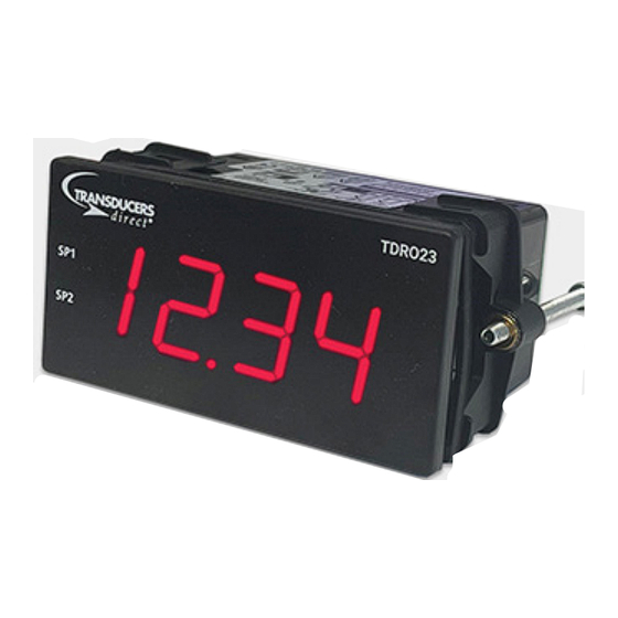
Large 0.8" super-bright display
›
Flexible 32 point linearization table
General Description
The TRDO23 universal digital indicator accepts
analog inputs from a range of industrial sen-
sors, including: process, temperature, flow,
frequency, and voltage from 200mV to 300V. It
features a wide range power supply that suits
both AC mains and 24V DC applications, and
supplies the excitation required for common
sensors and transmitters.
The TDRO23A0 can be scaled into any engi-
neering unit, and the result displayed on the
large 0.8" 4 digit super-bright LED display.
Auto ranging is available to increase the dy-
namic range of viewable data.
The TDRO23A2 adds two Form A 3 Amp relays
for a variety of control and alarm functions,
and a 4-20mA active output for retransmission
to PLCs and SCADA systems.
Quick start
Hardware
Install (p6)
Phone: 513-583-9491
Software
Install (p7)
www.TransducersDirect.com
Universal Indicator
The unit boasts a 1 minute setup time using
the Transducers Direct TDRO23 Config Tool. All
functions are explained expertly in the dynam-
ic sidebar help - perfect for the novice starting
out who can use it to learn about industrial
applications, or the expert who wants to save
commissioning time.
The TDRO23 has been designed for harsh in-
dustrial environments. With an IP65 sealed
bezel and extensive testing of noise effects to
and beyond CE requirements, the meter pro-
vides a tough and reliable application solution.
Software
Setup (p9)
TDRO23
Wiring (p12)
Page: 1
1
Advertisement
Table of Contents

Summary of Contents for TRANSDUCERS direct TDRO23
- Page 1 0.8" 4 digit super-bright LED display. Auto ranging is available to increase the dy- The TDRO23 has been designed for harsh in- namic range of viewable data. dustrial environments. With an IP65 sealed bezel and extensive testing of noise effects to...
-
Page 2: Table Of Contents
SAFETY NOTICES Contents ..............2 5.4 - Power Supply ........13 For your safety and the prevention of damage to the TDRO23 unit and other equipment Order Codes ............2 5.5 - Sensor Input ........14 connected to it, please read complete instructions prior to installation and operation of the TDRO23, and carefully observe all safety regulations and instructions. -
Page 3: Display
Relay output Environmental conditions OPTIONAL 1.2 - Display Type 2x Form A relays Operating humidity 5–85%RH max (non-condensing) Digits 4 digit red LED, 0.8" (20mm), Isolation to sensor and user input com- 7-segment characters mons 2,300Vrms for 1min Operating temperature 14 to 122°F Working voltage 240Vrms (-10 to 50°C) Display range -1999 to 9999... -
Page 4: Hardware Installation
IP65 require- TDRO23 into the Panel Cutout. Holding You must install Config Tool before connecting the TDRO23 to your computer. If you have already ments when properly installed. the unit in place, engage the Mounting Clips so that the tabs snap into place over connected the meter using the USB Key, please disconnect it before continuing. -
Page 5: Usb Key
TDRO23. This may cause loss of settings, or unexpected unit behaviour. CAUTION Not UL approved The USB Key is sold separately to the TDRO23 and has not been certified for UL. Fig 6 Phone: 513-583-9491 www.TransducersDirect.com... -
Page 6: Config Tool Interface Overview
4.3 - Config Tool interface overview TDRO23 universal indicator. To set up your indicator, only the USB Key is required - you do not need to supply power. Main Navigation Tabs Config Tool features a comprehensive help panel that will guide you through the setup of your Input/Output, Setpoints, and Advanced configuration pages. -
Page 7: Wiring
The TDRO23 features a wide range Power Supply that suits both AC mains be further improved, by: and 24V DC applications. The TDRO23 uses a full bridge rectifier, so it is not Using shielded cable on sensitive input sensitive to polarity for DC power inputs. -
Page 8: Sensor Input
5.5 - Sensor input See 5.3A, pins 1–6 INPUT TYPES The Sensor Input terminal can be wired to suit numerous input types. See Section 6 for input wiring, or refer to the Config Tool help panel as you are configuring the unit. CAUTION Risk of electric shock. -
Page 9: Rtd Input
6.2 - RTD input 6.3 - NTC input RTD input Pt100 or Pt1000 DIN 3-wire Sensor current 0.3mA nominal NTC -50 to 125°C (various thermistors) Accuracy Better than 0.4°C type (2-wire can be used with offset trim) Sensor break output drive Sensor types 10K Beta 3984/3435 Temperature drift <50ppm/°C Pt100 lead wire resistance 50Ω/wire max. -
Page 10: Current Input
6.4 - Current input 6.5 - Voltage input Range 0/4–20.000mA Max over-range 50mA DC continuous Ranges ±200mV, 200mV to 1V, 0–10V, Linearity and repeatability – ±10V, 10 to 30V, 0–300V <±0.02% FSO typical – Excitation +22V DC, 25mA max Linearity and repeatability (0–10V= <±0.05%;... -
Page 11: Digital Pulse
-10 to 30V DC 0–300V DC 6.6 - Digital pulse This is a general purpose voltage measur- This higher voltage general purpose range ing range, typically used to measure bat- is typically used to measure battery volt- Frequency range 0–2000.0Hz Software modes General frequency, Flow tery voltages, power supply outputs etc. -
Page 12: Potentiometer Input
6.7 - Potentiometer input 6.8 - AC current sensor Potentiometer input 3-wire Field prog span 0.1–100% Sensor type Current transformer Power supply ACCS-420 = Loop powered, 15–36V DC Excitation voltage Variable Linearity and repeatability Amperage range Header selectable ACCS-010 = Self powered <±0.05% FSO typical 100/150/200A;... -
Page 13: Maintenance & Service
The meter has been fully calibrated at the factory, and can be recalibrated in software using TDRO23 Config Tool (see Section 4). Scaling to convert the input signal to a desired display value is also done using Config Tool. -
Page 14: User's Responsibility
Transduc- full scale range due to EMC influence. and which are, after examination, disclosed ers Direct. to the satisfaction of Transducers Direct to be thus defective. User’s Responsibility We are pleased to offer suggestions on the In no event shall Transducers Direct’s liability,... - Page 15 12115 Ellington Ct Cincinnati, Ohio 45249 Ph: 513-583-9491 Fax: 513-583-9476 Email: Sales@TransducersDirect.com Phone: 513-583-9491 www.TransducersDirect.com Page: 28...
Need help?
Do you have a question about the TDRO23 and is the answer not in the manual?
Questions and answers