
Summary of Contents for Noraxon DTS FootSwitch
- Page 1 DTS FootSwitch User Manual DTS FootSwitch User Manual For questions, concerns or additional assistance please contact Noraxon or its Authorized Representative as specified below. P-5008 Rev I...
-
Page 2: Authorized European Representative
Noraxon and myoRESEARCH are registered trademarks and the Noraxon logo, myoANALOG, myoFORCE, myoMETRICS, myoMOTION, myoMUSCLE, myoPRESSURE, myoVIDEO, myoSYNC, NiNOX, TRUsync and Ultium are common-law trademarks of Noraxon U.S.A., Inc. All other trademarks are the property of their respective owners. ©2018, all rights reserved. -
Page 3: Table Of Contents
DTS FootSwitch User Manual Table of Contents Section 1: Introduction Brief Description ........................... 1 Intended Use ..........................1 Contraindications .......................... 1 Section 2: Definitions Graphic Symbols and Meaning ....................2 Glossary of Terms ........................3 Section 3: Identification Model Designation ........................4 Product Versions and Configurations ................... - Page 4 DTS FootSwitch User Manual Section 8: Operating Instructions Safety Information Summary ...................... 16 Normal Functions with Interface to a PC..................16 Exceptional Functions/Situations (error messages)..............17 Shutdown after Use ........................17 Storage and Protecting Between Usages .................. 17 Section 9: Accessories and Optional Modules Accessories ..........................
- Page 5 Appendix D – Radio Regulatory Statements ................34 Appendix E – FSR Usage Tips....................34 Appendix F – Insole measurements ................... 39 Appendix G – DTS FootSwitch Sensor Sensitivity ..............40 Appendix H – DTS FootSwitch Belt Receiver Setup..............42 P-5008 Rev I...
-
Page 6: Section 1: Introduction
FootSwitch sensor has functionality for Noraxon DTS EMG systems as well as the new MyoMotion system. The wireless DTS Footswitch has universal functionality covering easy and quick to use setups for clinical gait screening, running and jump testing. If damage occurs due to heavy impact or shear forces (running/jumping), broken sensors are easily replaced. -
Page 7: Section 2: Definitions
Section 2: Definitions Graphic Symbols and Meaning The following international icons and symbols are found on the DTS FootSwitch sensor enclosures and in this user manual. Their meaning is described below. This symbol indicates the clearance to market this product in the European Community. -
Page 8: Glossary Of Terms
DTS FootSwitch User Manual Glossary of Terms DTS – (Abbreviation for Direct Transmission System) A network of short-range wireless sensors where measured data is transmitted directly from each sensor into a receiver for subsequent display and analysis on a computer or intelligent handheld device. -
Page 9: Section 3: Identification
Model Designation Model 500 DTS FootSwitch Product Versions and Configurations The model 500 DTS Footswitch sensors can work in conjunction with any of the Noraxon DTS EMG systems or the Noraxon MyoMotion system. Model 580 TeleMyo DTS Belt Receiver Model 584 Clinical DTS Receiver... -
Page 10: Section 4: General Warnings And Cautions
Section 4: General Warnings and Cautions Risks and Benefits There is no identified risk of physical harm or injury with use of the DTS FootSwitch sensor. The benefit provided by use of the device is the provision of objective measures to assess the severity of pathological human movement conditions and gauge any subsequent improvement offered by therapy, training, prosthetic alterations or ergonomic design changes. -
Page 11: Section 5: Getting Started
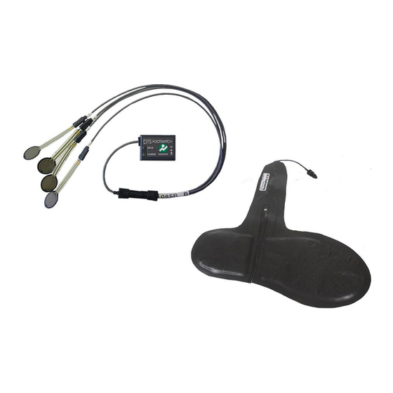
Please see the hardware manual for the appropriate EMG system. Section 6: Preparing the Product for Use (Set-up Instructions) Unpacking and Component Identification DTS FootSwitch Lead Set (Part #500) DTS FootSwitch FSR Sensor Assembly (Part #085B) DTS FootSwitch Insole (Part #085F) -
Page 12: Component Inputs, Outputs And Indicators
DTS FootSwitch User Manual 2 x Fabrifoam Strap 18 inch (Part #ES1) Additional contents not illustrated DTS FootSwitch User Manual (part #500A) This document If additional accessories have been included please see Section 9, Accessories for component identification. Component Inputs, Outputs and Indicators 1A DTS Sensor (front) Status –... -
Page 13: Component Interconnections
DTS FootSwitch User Manual Component Interconnections Step 1A Connect the DTS Footswitch connector (Male 5-pin connector) with the FSR connector (Female 5-pin connector) Step 1B Connect the DTS Footswitch connector (Male 5-pin connector) with the DTS Insole connector (Female 5-pin... -
Page 14: Companion Software Installation
MR3 software. Companion Software Configuration Before the DTS Footswitch can be used with the Noraxon EMG system can be used, the companion software must be configured to recognize the different components that make up the system. -
Page 15: Myoresearch Xp Configuration
When the serial number is entered, the sensor should automatically be detected as a DTS FootSwitch. Once finished entering all the serial numbers, Select OK until you are returned to the Measurement Configuration screen. - Page 16 Foot Switch/Sole icon box Step 4b Click on the check box next to the channel the DTS FootSwitch is assigned to. The channel will default to EMG, but this can be changed by double clicking the Type of sensor and scrolling to...
-
Page 17: Mr3 Configuration
DTS FootSwitch User Manual MR3 Configuration Step 1 Enter the Hardware Setup screen and setup the Noraxon EMG system in accordance with its provided hardware manual. Step 2 Enter the device hardware configuration and to enter the DTS FootSwitch serial numbers into the... - Page 18 EMG or myoMOTION channels and sensors will appear below. The DTS FootSwitch should automatically appear, as detected by the DTS or myoMOTION system. To select the FootSwitch for use in...
-
Page 19: Section 7: Pre-Use Check-Out
STATUS indicator will flash recognizably faster. If the STATUS indicator is not flashing at all, the DTS FootSwitch Sensor must be placed in a powered DTS sensor charger station to be reactivated. This could be due to a depleted sensor battery or if the sensor has been deliberately placed in a special shut down mode. -
Page 20: Sensor Placement
DTS FootSwitch User Manual method to measure foot pressure. The sensitivity of the insole is adjustable, which allows the user freedom to set the pressure for each subject. The insole is available in Men’s, Women’s and Children’s sizes. Sensor Placement FSR Placement Tape the sensors to the foot as shown below;... -
Page 21: Calibration
Never use the Noraxon System on a person with an implanted pacemaker • Never operate the Noraxon DTS System within 1 meter of any critical medical device Normal Functions with Interface to a PC When used with the companion software the Inline FootSwitch displays and records signal similar... -
Page 22: Exceptional Functions/Situations (Error Messages)
Note: The Belt Receiver requires a special setup for use with the FootSwitch sensors. Please see Appendix H for detailed instructions. Exceptional Functions/Situations (error messages) Please see the appropriate Noraxon system’s hardware manual for possible error messages. Shutdown after Use At the end of the day: •... - Page 23 DTS FootSwitch User Manual P-5008 Rev I...
- Page 24 Click on the Setup button at the lower middle of the screen • Click on the Hardware button in the right side Actions toolbar • Click on the correct Noraxon Receiver icon • Click on the Configure Device button •...
-
Page 25: Section 9: Accessories And Optional Modules
Elastic strap for adhering the sensor to the user 542C Double sided tape for attaching DTS sensors, 504 per package As new accessories may be available after the time of printing, please check Noraxon’s website at this link for the latest offerings. http://noraxon.com/products/ Interfaces to Other Devices Part No. -
Page 26: Section 10: Cleaning
Do not immerse DTS Sensors in any water or liquid. Cleaning by Users The DTS Footswitch FSR’s should be wiped off with a damp cloth between uses. The individual sensors are replaceable parts and should be replaced when damaged. The foot insoles should be wiped off with a damp cloth between uses. The foot insoles should be replaced when damaged. -
Page 27: Section 11: Maintenance
Companion Software Updates • Perform a backup of the data folders to a separate drive as a precaution. • Click on the Patch/Update link provided in the email or as given on the Noraxon website • http://noraxon.com/software-downloads • Download the Patch/Update file. -
Page 28: Device Software (Firmware) Updates
Device Software (firmware) Updates The internal program (firmware) inside the various DTS devices can be updated through the use of a special utility program available through a supplied link through the Noraxon website: http://noraxon.com/drivers-and-firmware The installed firmware program will permit updates to both the Receiver and the DTS Sensors... -
Page 29: Section 12: Trouble Shooting, Fault Diagnosis
(esp. at long distances) of-sight relationship between sensor and receiver Website Link to FAQ Answers to common questions can be found at Noraxon’s Frequently Asked Questions (FAQ) website page at this link: http://noraxon.com/faq Other educational material is available at this link: http://noraxon.com/educational-materials... -
Page 30: Radio Considerations
WiFi enabled devices. Despite all this competing radio activity the Noraxon systems are able to discern its particular information from all the surrounding radio traffic. Reliable transmission depends on good signal quality. -
Page 31: Section 13: Service And Repair
If you are shipping from outside the USA please use UPS, FedEx, DHL, or EMS (US Postal Service) and not a freight-forwarder. Using a freight-forwarder incurs additional brokerage fees. If a package is shipped to Noraxon via a carrier other than the ones listed above, it may be refused. -
Page 32: Section 14: Spare Parts And Consumables
DTS FootSwitch User Manual Section 14: Spare Parts and Consumables Consumable Items Part Image Description 542C Double sided tape for attaching DTS sensors, 504 per package Replaceable Items Part Image Description FSA1 Inline FootSwitch FSR Sensor Assembly 085F Foot Insole... -
Page 33: Section 16: Specifications Of The Product
Section 16: Specifications of the Product Expected Useful Lifetime The DTS FootSwitch sensor has a usable life of seven years. The DTS sensors operate with a rechargeable Lithium Ion battery. The battery capacity will decline with ongoing use and require replacement after 300+ discharge/charge cycles to preserve the device’s rated 8 hours of operating time. -
Page 34: Section 17: Technical Information
Wireless USB product by Cypress Semiconductor. Part 500 FootSwitch (DTS FootSwitch Sensor) Each DTS Footswitch sensor (part # 500) incorporates one Unigen transceiver module together with a preamplifier / data acquisition motherboard. The 500 is powered by one 382030 battery (190maH). -
Page 35: Electro-Magnetic Compatibility Tables
DTS FootSwitch User Manual Electro-Magnetic Compatibility Tables Guidance and manufacturer’s declaration – electromagnetic emissions The DTS sensor is intended for use in electromagnetic environment specified below. The customer or the user of the DTS sensor should assure that it is used in such an environment. - Page 36 DTS FootSwitch User Manual Guidance and manufacturer’s declaration – electromagnetic immunity The DTS sensor is intended for use in electromagnetic environment specified below. The customer or the user of the DTS sensor should assure that it is used in such an environment.
- Page 37 DTS FootSwitch User Manual Recommended separation distances between portable and mobile RF communications equipment and the DTS System The DTS sensor is intended for use in an electromagnetic environment in which radiated RF disturbances are controlled. The customer or the user of the DTS sensor can help prevent electromagnetic interference by maintaining a minimum distance between portable and mobile RF communications equipment (transmitters) and the DTS sensor as recommended below, according to the maximum output power of the communications equipment.
-
Page 38: Section 18: Appendices
DTS FootSwitch User Manual Section 18: Appendices Appendix A – Interference Between WiFi and DTS Radio Frequency Channels Because any neighboring WiFi radios and the DTS System share the 2.4GHz frequency spectrum there is the possibility that the RF channels may overlap and interfere with each other resulting in lost data. -
Page 39: Appendix B - Sensor Rf Channel Frequencies
DTS FootSwitch User Manual Appendix B – Sensor RF Channel Frequencies The EMG Sensors and Biomechanical Sensors operate on a RF channel. The RF Channels (A- H) are assigned to the RF frequencies according to the table below. RF Channel Frequency (GHz) 2.400-2.409... -
Page 40: Appendix C - Radiation Exposure Information Regarding Use Of Dts Sensors
(next to the person’s head). At present, Noraxon identifies no restrictions on use and placement of the DTS sensors on any portion of the human body. The DTS sensors operate at radio frequencies known to effect older style pacemakers. -
Page 41: Appendix D - Radio Regulatory Statements
DTS FootSwitch User Manual Appendix D – Radio Regulatory Statements FCC Statement This device complies with part 15 of the FCC rules. Operation is subject to the following two conditions: (1) This device may not cause harmful interference, and (2) this device must accept any interference received, including interference that may cause undesired operation. -
Page 42: Appendix E - Fsr Usage Tips
DTS FootSwitch User Manual Appendix E – FSR Usage Tips Care and Handling Do’s: Do handle the FSR with care. Do gently bend the FSR in the middle of the tail. Do adjust the sensitivity of the FSRs. Do pull the FSR straight out of the cable. If the FSR is bent near the connector, the pins can break off and get stuck inside the cable. - Page 43 DTS FootSwitch User Manual 4. On regular shoe soles ▪ Sometimes research studies require the FSR to be placed on the shoe sole. This method may be used, but it requires careful setup so the FSR is not damaged. ▪...
-
Page 44: Appendix F - Insole Measurements
DTS FootSwitch User Manual Appendix F – Insole measurements The insoles are worn in the subject's shoes or taped to the bottom of bare feet. The foot insole has 4 quadrants – toe, metatarsal 1, metatarsal 5, heel. The heel section is separated from the fore foot section so that one pair of insoles can accommodate a range of shoe sizes. -
Page 45: Appendix G - Dts Footswitch Sensor Sensitivity
DTS Footswitch Sensor(s) value for each FSR using software, e.g. MyoResearch XP, to verify that the voltages match the values on the next page. 9. Typically, if two DTS Footswitch Sensors are used, both sensors will be set to the same sensitivity. - Page 46 DTS FootSwitch User Manual DTS FootSwitch Translation into Voltages Individual Values Normal Step Sequence Values (in Volts) (in Volts) H = 0.267 Volts = 0.267 5 = 0.533 Volts H, 5 = 0.800 1 = 1.067 Volts H, 5, 1 = 1.867...
-
Page 47: Appendix H - Dts Footswitch Belt Receiver Setup
8 channel Belt Receiver the FootSwitches are assigned to channels 10-11. a. Assign the DTS FootSwitch Sensor b. Edit the DTS FootSwitch sensor so it is assigned to the correct serial number 2. Enable the FootSwitch Sensors in the belt receiver. Please refer to the TeleMyo DTS User manual for detailed instructions on how to do this.
Need help?
Do you have a question about the DTS FootSwitch and is the answer not in the manual?
Questions and answers