
Summary of Contents for ProMik MSP1000 NET
-
Page 1: Msp1000·Net
MSP1000 NET User Manual MSP1000·NET Hardware Revision 1 Manual_MSP1000Net Rev. 3.0 Page 1 of 18... -
Page 2: Table Of Contents
Introduction ............................. 3 Application Domain ........................3 Configuration ..........................4 Establishing the network connection ....................7 Assigning a new IP Address to MSP1000 NET ................8 LED Displays ..........................10 Manually Operation Buttons ......................11 Mechanical Dimensions ........................ 12 Electrical Data ..........................12 Programming Interface Pin-Out .................... -
Page 3: Introduction
MSP1000 NET User Manual Introduction The MSP1000 NET Programmer (referred in this document as "Programmer“) was designed specially for In-Line Programming applications. To be able to communicate at very high speeds, short communication lines between the Programmer and target MCU are required. -
Page 4: Configuration
User Manual Configuration Since MSP1000 NET is an Ethernet appliance, there is therefore need to assign it with a domain network IP address during first network installation. The MSP1000 NET Programmers generally leave the factory with the IP address "192.168.1.1". To avoid future network conflicts, it is strongly recommended to always assign the MSP1000 NET with a new IP address. - Page 5 MSP1000 NET User Manual Fig. 2 Fig. 3 Fig. 4 Fig. 5 Manual_MSP1000Net Rev. 3.0 Page 5 of 18...
- Page 6 Panel", then "Network and Internet", and finally “Network and Sharing Center”. Select the network card/adapter which is connected to the MSP1000 NET and add a TCP/IP address (e.g. 192.168.1.100 with subnet mask 255.255.255.0) to it so that you can be able to able to establish a network connection with the MSP1000 NET.
-
Page 7: Establishing The Network Connection
Fig. 11 Establishing the network connection Power the MSP1000 NET and connect it to a PC via a standard CAT5 STP cable. Important! At this stage, the MSP1000 NET and the PC should be isolated from your corporate LAN, unless you are 100 percent sure that the MSP1000 NET preset IP address is not being used by other network nodes. -
Page 8: Assigning A New Ip Address To Msp1000 Net
MSP1000 NET User Manual Assigning a new IP Address to MSP1000 NET Your MSP1000·NET is usually supplied with PC software which is used for programming your target hardware. Additionally, you also receive a small configuration tool "MSP1Config.exe" with which you can configure your MSP1000·NET as already described above. - Page 9 Fig. 15 Tipp: For reference's sake, note down the IP address now assigned to your MSP1000 NET. What do you do, if you forget which IP address you assigned to your MSP1000·NET? In this situation, the configuration tool can help you.
-
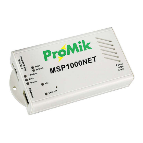
Page 10: Led Displays
MSP1000·NET via broadcast also depends on the network configuration of your PC. LED Displays When the MSP1000 NET is connected to other active Ethernet appliances (e.g. network hub/ network switch, or network card of your PC) then the green "Link/Act" LED as well as the yellow/orange "Dulpex"... -
Page 11: Manually Operation Buttons
MSP1000 NET User Manual MSP1000 NET signalizes the target programming operation through activating the yellow/orange "Busy" LED, and the module voltage to the target through the green "U_Module" LED. Manually Operation Buttons The MSP1000·NET has no operation buttons. Manual_MSP1000Net Rev. 3.0... -
Page 12: Mechanical Dimensions
MSP1000 NET User Manual Mechanical Dimensions Size: appr. 122 x 29 x 69 (B x H x T), with Mounting area 145 x 29 x 69 Weight: appr. 160 g Electrical Data Power Supply: 15 Vdc Current consumption: appr. 130 mA Temperature Range: 0 –... -
Page 13: Programming Interface Pin-Out
MSP1000 NET User Manual Programming Interface Pin-Out Connector viewed from the top. Pin 1 Pin 2 GPIO Pin 3 TDI/BKGD Pin 4 UMOD Pin 5 Pin 6 Pin 7 Pin 8 CLKE Pin 9 Pin 10 Pin 11 TCLK Pin 12... - Page 14 MSP1000 NET User Manual Fig. 17 Front View Fig. 18 Back View Manual_MSP1000Net Rev. 3.0 Page 14 of 18...
-
Page 15: Mounting The Programming Connector
MSP1000 NET User Manual Mounting the Programming Connector Programming Connector AMPMODU 50/50 To remove the programming connector press on the latch to unlock it while pulling the connector out. For a safe connection the locking latch must engage underside of the locking bar. -
Page 16: Optional Din Rail Mounting Kit
MSP1000 NET User Manual Optional DIN Rail Mounting Kit Pull the tab to quickly disconnect the MSP from the DIN rail. Pull the tab to quickly attach the MSP to the DIN rail. Manual_MSP1000Net Rev. 3.0 Page 16 of 18... -
Page 17: Fcc Compliance Statement
MSP1000 NET User Manual FCC Compliance Statement This equipment has been tested and found to comply with the limits for a Class A digital device, pursuant to part 15 of the FCC Rules. These limits are designed to provide reasonable protection against harmful interference when the equipment is operated in a commercial environment. - Page 18 MSP1000 NET User Manual Manual_MSP1000Net Rev. 3.0 Page 18 of 18...
Need help?
Do you have a question about the MSP1000 NET and is the answer not in the manual?
Questions and answers