
Subscribe to Our Youtube Channel
Related Manuals for Moore Industries STA

Summary of Contents for Moore Industries STA
- Page 1 Demand Moore Reliability TPRG User’s Manual Programmable RTD, T/C, Ohms, mV 225-748-00P and Potentiometer Safety Trip Alarm August 2024 www.miinet.com...
-
Page 2: Customer Support
We perform a sequence of stringent quality assurance checks on every unit we ship. If any Moore Industries product fails to perform up to rated specifications, call us for help. Our highly skilled staff of trained technicians and engineers pride themselves on their ability to provide timely, accurate, and practical answers to your process instrumentation questions. -
Page 3: Safety Messages
All Moore Industries instrumentation should only be used for the purpose and in the manner described in this manual. If you use this product in a manner other than that for which it was intended, unpredictable behavior could ensue with possible hazardous consequences. -
Page 4: Table Of Contents
Operation ............................... 61 STA Diagnostics & Fault Alarms ........................61 STA Diagnostic Messages ..........................62 Maintenance ..............................63 Section 7 - STA in Safety Instrumented Systems Proof Test Procedure ............................ 68 Section 8 - Applications High Integrity Alarm Trip ..........................70 High Availability Architecture ........................ -
Page 5: Sta (Tprg) Quick Start Guide
The STA configuration can be recorded using the worksheet found at the end of this manual. Please contact Moore Industries Sales for an interactive version of the worksheet. -
Page 6: Default/Factory Configuration
Optional Analog Output (AO): Current, No Damping, Fail Low, Scaled to 4-20mA Display: Process Variable (PV), Auto Decimal Point, 60Hz Filter Broken Wire Detection: Level Set to 0 (disabled) Password: 1 Note: *For STA units with firmware versions 1.5 and earlier, these defaults are not configurable. www.miinet.com - 6 -... -
Page 7: Section 1 - Introduction
It also has one fault alarm output which is triggered by a self-diagnosed failure of the input or the STA itself. The STA is typically used to activate a warning light, bell or buzzer; or to initiate a system shutdown. Thus, the instrument acts as a simple, but highly reliable and effective means of monitoring and safe-guarding a process. - Page 8 LED (Red/Green) is provided with each alarm to indicate its condition. The fault alarm trips on a self-diagnosed failure within the STA or on any of its inputs. This alarm is latching and has to be reset by the user. Only user configuration faults will clear automatically once the configuration is valid.
- Page 9 *Power supply option no longer available for purchase. OPTIONS If your STA has the Analog Output option, Analog Output can be configured to provide a voltage (0-10V) or current (0-20mA) output. The current output can be sink or source. Refer to the Configuring the Analog Output section of this manual for additional information.
-
Page 10: Alarm Terminology
The Trip Point is the process input level at which the user wants an alarm relay to change state, typically going into an alarm condition, or “tripping”. In the STA, the user sets the trip point for each installed relay. - Page 11 Non-failsafe alarms are energized whenever tripped, de-energized when the process input is at a non-alarm level. The relays in the STA are failsafe only. Normal is the term used to describe the “shelf-state” of relay contacts. The contacts of a Normally Open relay are open (infinite resistance) when the relay is not energized.
-
Page 12: Section 2 - Calibration And Bench Check
The bench check is a quick way to determine that your STA is functioning as expected. Depending on your organization’s requirements, you may also be required to perform a complete Proof Test on your STA. The instructions for the Proof Test can be found in Section 7 of this manual. - Page 13 Bench Check Procedure 1. Sensor Input: In order to provide an input to your STA TPRG you will need to use an appropriate input simulator. By example – if you plan to use your STA with a thermocouple input you will need to use a thermocouple simulator to provide the appropriate input during your bench check.
- Page 14 Type T thermocouple and your input range is set for 0-100° C then use a Type T thermocouple simulator and set it to simulate 0° C. Verify that the STA is reading 0° C on its display window.
-
Page 15: Section 3 - Installation And Wiring
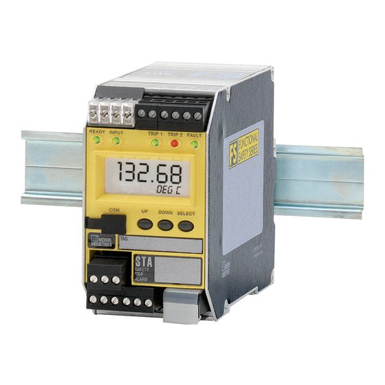
STAs. Note: Any changes to Security Settings will need to be made prior to installation and wiring refer to Security Settings later in this section. Dimensions Figure 3.1. Dimensions of Aluminum DIN-Housed STA TPRG 132.68 DEG C 56mm 142mm (2.2 in) - Page 16 The STA is housed in a DIN case that can be mounted on 35mm Top-Hat (EN50022) DIN-rail. To mount the STA on a Top-Hat DIN-rail, seat the upper extrusion on the unit back panel over the top lip of the rail and pivot downward until the housing locks into place. When mounting multiple units, like a rack or cabinet, make sure to allow adequate vertical spacing for pivoting the units.
-
Page 17: Terminal Designations
INPUT INPUT GROUND 4-20mA Output Loop 4-20mA Output Loop Voltage Signal Voltage sourced by DCS Voltage sourced by STA Output from STA NOTES: KEY: 1. Terminal blocks can accommodate 14-22 AWG solid Io = Current Output Sink = Current Sink AC or DC = Power Input wiring. - Page 18 TPRG User’s Manual 225-748-00P Programmable RTD, T/C, Ohms, mV and Potentiometer Safety Trip Alarm August 2024 Figure 3.5. STA (TPRG) Hook-Up Diagram MILLIVOLT SOURCE OR T/C SIMULATOR See Table 3.4 for Sensor Hook-up Guide OHMS OR RTD SIMULATOR READY INPUT...
-
Page 19: Installation In Hazardous Locations
Specific conditions of use The following instructions must be adhered to when the STA is used in hazardous locations and potentially expliove atmosphres. The STA shall be installed in complaince with the enclosure, mounting, spacing, and segrgation requirementsof the ultimate application. -
Page 20: Electrical Connections
Switches and Circuit Breakers For STA AC powered units, a switch or circuit breaker must be wired in series with the AC power conductors. The switch or circuit breaker used must be located within three meters of the unit. -
Page 21: Contact/Load Suppression
EMC directive. The Low Voltage Directive also applies to the AC powered versions of the STA and/or when connecting any of its output relay contacts to voltages greater than 50 vac. In order to comply with EN61010-1 (Low Voltage Directive) all guidelines in this section must be followed. -
Page 22: Security Settings
Password Required – A one to four-digit access code is required to gain access to the STA configuration menu. If the correct code is entered, full read and write operation is permitted. If an incorrect code is entered, “WRONG PASWD”... -
Page 23: Section 4 - Sta Front Panel Configuration
Figure 4.1 gives an overview of the View menu. Upon power-up, the STA displays a ‘SYS INIT’ message until the power up self test is complete. In normal operation the View menu will display the variable as configured. This can be the process variable, the analog output variable, or both being toggled (Refer to Configuring the Options Menu for more details). - Page 24 MAIN Menu (Enter Pass) (Display of Variable) Display of MAIN Menu other var XXXXX MAIN Menu ZERO XXXXX MAIN Menu FULL XXXXX MAIN Menu AL1 X* XXXXX MAIN Menu (Enter Pass) AL2 X* www.miinet.com - 24 - Moore Industries-International, Inc.
-
Page 25: Main Configuration Menu
Pressing the SELECT button accesses the first screen of the sub-menu shown on the LCD. Note: STA is programmed to time out from the configuration menu after 5 minutes of inactivity. When trimming the unit, 30 minutes of inactivity are allowed before the time out. If the unit times out, the previous settings will be reapplied. - Page 26 CONFG AOUT AOUT menu SCALE SCALE AOUT AOUT menu TRIM TRIM AOUT AOUT menu CONFG CONFG OPTNS OPTNS menu CONFG CONFG PASWD PASWD menu RESET RESET FAULT FAULT CONFG CONFG EXIT EXIT menu www.miinet.com - 26 - Moore Industries-International, Inc.
- Page 27 Warning: The default value for INPUT OOR is 1% of Span. For safety applications, the INPUT OOR value must be set to 2% of Span or less. Note: For STA units with firmware versions 1.5 and earlier, OOR is not configurable and the value is set to 1%.
- Page 28 DEG C INPUT DEG F ZERO Value Change: KELVIN XX.XX DEG R INPUT FULL Value Change: XX.XX INPUT Value ZERO Change: XX.XX INPUT INPUT FULL Value Change: XX.XX EXIT EXIT SENSR SCALE INPUT menu www.miinet.com - 28 - Moore Industries-International, Inc.
-
Page 29: Scaling The Input
Scale Mode– This allows you to customize your display for your application. For example, if your process is sending a 32°-212° reading to the STA and you wish to view the input as 0-100% then this can be accomplished with the Scale Mode feature. - Page 30 Figure 4.4. SCALE INPUT Menu SCALE INPUT Selection: SCALE SCALE OFF MODE SCALE ON SCALE Set Chars: X---- SCALE Value Change: ZERO XX.XX ZERO SCALE Value Change: FULL XX.XX FULL EXIT SCALE TRIM INPUT menu www.miinet.com - 30 - Moore Industries-International, Inc.
-
Page 31: Input Trimming
Sensor trimming increases the measurement accuracy of your instrument by matching the reading of its actual input to its scaling. The STA offers the use of a factory-configured trimming feature (“FCTRY TRIM”) or user-set, one-point or two-point (“USER 1 PNT” OR “USER 2 PNT”) trimming. - Page 32 RESET YES TRIM Change Value: Capture Value: ZERO XX.XX XX.XX APPLY (Flashing) ERROR TRIM TRIM Change Value: Capture Value: FULL XX.XX XX.XX APPLY (Flashing) ERROR FCTRY TRIM TRIM EXIT TRIM CONFG ALARM menu www.miinet.com - 32 - Moore Industries-International, Inc.
-
Page 33: Configuring The Alarm(S)
August 2024 Configuring the Alarm(s) The STA has one relay which is an Fault alarm and two user-configurable Trip alarms. The Fault alarm has limited configuration with respect to trip alarms. All diagnostic faults will be latched and must be reset by cycling power to the unit. Input faults can be configured to be latched/unlatched and can also be configured to be reset by the Manual Reset (MR) in addition to front panel reset. - Page 34 Note: For STA units with firmware versions 1.5 and earlier, the INPUT FAULT and MANL RESET options are not present. The fault alarm is always latched and cannot be reset by MR.
- Page 35 HOLD LAST– This will cause the analog output to maintain the last valid value present before the failure. Note: The AO must be set to fail low if used in a safety system - please refer to section 7 for more information Moore Industries-International, Inc. www.miinet.com - 35 -...
- Page 36 Programmable RTD, T/C, Ohms, mV and Potentiometer Safety Trip Alarm August 2024 Figure 4.7. CONFG AOUT Menu CONFG AOUT Selection: VOLT AOUT CURNT Value Change: DAMP Selection: FAIL FAIL HIGH MODE FAIL LOW HOLD LAST EXIT AOUT SCALE AOUT menu www.miinet.com - 36 - Moore Industries-International, Inc.
-
Page 37: Scaling The Analog Output (-Ao Option)
In either case there needs to be a minimum Span of 4mA or 1V. Figure 4.8. SCALE AOUT Menu SCALE AOUT Value Change: AOUT XX.XX ZERO MA/VOLT AOUT Value Change: FULL XX.XX MA/VOLT EXIT SCALE TRIM AOUT menu Moore Industries-International, Inc. www.miinet.com - 37 -... -
Page 38: Trimming The Analog Output (-Ao Option)
Figure 4.9 gives an overview of the Analog Output Trimming menu. Output trimming increases the measurement accuracy of the STA by calibrating its analog output to the device that is receiving the output. This ensures that the instrument is being correctly interpreted. - Page 39 Figure 4.9. TRIM AOUT Menu TRIM AOUT Value Change: TRIM XX.XX ZERO MA/VOLT TRIM Value Change: XX.XX FULL MA/VOLT FCTRY Selection: TRIM RESET NO RESET YES TEST Value Change: AOUT XX.XX MA/VOLT EXIT TRIM CONFG OPTNS menu Moore Industries-International, Inc. www.miinet.com - 39 -...
- Page 40 TPRG User’s Manual 225-748-00P Programmable RTD, T/C, Ohms, mV and Potentiometer Safety Trip Alarm August 2024 Figure 4.10. STA (TPRG) Trimming Hook-Up Diagram MILLIVOLT SOURCE OR T/C SIMULATOR OHMS OR RTD SIMULATOR READY INPUT TRIP 1 TRIP 2 FAULT DOWN...
-
Page 41: Configuring The Options
“START DELAY” appears; press SELECT. Here the desired startup delay can be entered by using the UP or DOWN buttons. This adds a delay after the STA has been initialized to allow the process input to stabilize. During initialization and delay all outputs are held in their failsafe mode. - Page 42 FILTR 50 HZ 60 HZ START DELAY Change Value: XXX SEC DSPLY TEST Display test is executed, returns to FCTRY CONFG. FCTRY Selection: CONFG RESET NO RESET YES EXIT OPTNS CONFG PASWD menu www.miinet.com - 42 - Moore Industries-International, Inc.
-
Page 43: Password Configuration
The “EXIT PASWD” appears. Press SELECT , to exit, “RESET FAULT” menu will appear. Note: If the security is set to Full Access, a password can be set but will not be requested to use and configure the STA unit. Please refer to Security Settings in Section 3. Figure 4.12. CONFG PASWD Menu... -
Page 44: Reset Fault
RESET FAULT will clear all input related faults. All unit faults must be cleared by power cycling the unit. If a fault is still present after these steps, please contact Customer Service for further assistance. Refer to Table 6.1 for a full list of STA diagnostic messages and corrective actions. Figure 4.13. RESET FAULT... - Page 45 If “ERROR UNDO” is selected, you will be returned to View menu and no changes will be applied to unit (previous configuration will remain unchanged). Figure 4.14. CONFG EXIT Menu CONFG EXIT ENTER VIEW MENU PASS Selection: SEL (error) ERROR LIST? SEL UNDO ERROR UNDO? ENTER CONFG INPUT Moore Industries-International, Inc. www.miinet.com - 45 -...
-
Page 46: Section 5 - Sta Pc Configuration
The STA must be connected to the PC in order to: trim input, trim output, assign a tag, perform a loop test, receive (via download) a configuration file, and save the configuration file (via upload) from the STA’s memory. - Page 47 August 2024 PC Software Configuration One of the benefits of the STA is that you may either use the external push button controls to set up the instrument, or use a PC and Moore Industries’ Intelligent PC Configuration software. In using the software program, settings are downloaded to the instrument in the form of a Configuration File and stored in the instrument’s memory.
- Page 48 Out of Sync (yellow light) No Device (grey light). 3. Program Status– This portion of the program displays the activity of the connected unit. It will display such messages as: Reading STA Info, Idle, Monitoring Variables and Monitor Fail. www.miinet.com - 48 -...
- Page 49 “Reset Input Fault” button, or by power cycling the unit. Internal faults require the unit to be power cycled and will not be cleared by this button. See STA Diagnostics & Fault Alarms in Section 6 for more information.
-
Page 50: Menu And Tool Bar Legend
Note: Changes that have been made and not downloaded to the unit will be discarded. While the unit is in monitoring mode the STA Status Section and Variables Section will be continuously updated. This includes the PV and AO (only applicable if unit has AO). - Page 51 August 2024 Using PC Configuration Software Offline When using the STA PC Configuration without a unit connected or properly communicating with software (offline) it is important to know that the following items will be greyed out and disabled from making changes.
- Page 52 Full and Input Zero are limited 0% to 5 % of the Current Span. Current Span is displayed above along with Sensor Limits and Minimum Span. Note: For STA units with firmware versions 1.5 and earlier, OOR is not configurable and the value is set to 1%.
- Page 53 Start Up Delay– This allows you to set a Start up Delay of 0-120 seconds (default is 0). This adds a delay after the STA has been initialized to allow the process input to stabilize. During initialization and delay all outputs are held in their failsafe mode.
-
Page 54: Input Scaling
Input Scaling– This allows you to customize your display for your application. By example: if your process is sending a 0-4000ohms signal to the STA and you wish to view the input as 0-100% then this can be accomplished with the Scaling feature. - Page 55 Precision– Select the number of decimal places/resolution of your display (default is Auto). Note: Once you have configured all parameters, download to the unit by selecting “Download” in the Transfer dropdown menu located in the Status Bar. Or, click the button in the Menu Bar. Moore Industries-International, Inc. www.miinet.com - 55 -...
- Page 56 Alarm Mode– Click the appropriate button to configure your alarm as a High Alarm or Low Alarm Trip Point – Set this Point to have STA unit notify you if your process input drops below, or exceeds your trip point setting depending on Alarm Mode select by user.
- Page 57 Programmable RTD, T/C, Ohms, mV and Potentiometer Safety Trip Alarm August 2024 Latching- By default, alarms will be unlatched. Select this to configured the STA with a latching alarm, this alarm condition will not “clear” (the relay will not change state) until the input returns to a non-alarm state AND manual reset terminals are shorted and then opened.
- Page 58 Note: Once you have configured all parameters, download to the unit by selecting “Download” in the Transfer dropdown menu located in the Status Bar. Or, click the button in the Menu Bar. www.miinet.com - 58 - Moore Industries-International, Inc.
- Page 59 1. Ensure that STA monitoring is stopped. In the “Fix current / voltage” text box, enter a value between 0-23.8mA (for current) or -5-11V (for voltage) and click the “Fix” button. 2. Return to monitoring the STA. You will see the “fixed” value in the “AO” field in the Variables Section and on the external multimeter.
- Page 60 Note: When user uploads a configuration from unit and then alters the displayed configuration a [modified] tag will be displayed before the Device Tag in Summary Tab. Once you download configuration to unit the [modified] tag will disappear. www.miinet.com - 60 - Moore Industries-International, Inc.
-
Page 61: Section 6 - Operation And Maintenance
Programmable RTD, T/C, Ohms, mV and Potentiometer Safety Trip Alarm August 2024 Section 6 - Operation and Maintenance When the STA is used in a SIL rated safety application, please refer to the Safety Instrumented Systems section of this manual before operating your unit. Operation Once calibrated, installed, and supplied with the correct power, the STA begins to operate immediately. -
Page 62: Sta Diagnostic Messages
(Slow degradation is characterized by events that occur over a span of a second or so). STA Diagnostic Messages Every STA is subjected to a complete suite of operational checks and tests prior to its shipment. Occasionally, however, units can sustain damage in transit from the factory to the user. -
Page 63: Maintenance
Note: The Manual Reset (MR) will only reset Input Faults if configured in the Alarms Menu. Maintenance Moore Industries recommends that the calibration of this instrument should be checked every year and re-calibrated only when necessary. In addition, we suggest a quick check for terminal tightness and general unit condition. -
Page 64: Section 7 - Sta In Safety Instrumented Systems
The STA has been certified, by exida ®* to IEC61508:2010 for systematic integrity up to SIL3 and for random integrity up to SIL2. This means that an STA is approved for single use in Safety Instrumented Systems (SIS) up to SIL2 and in a redundant architecture (1oo2, 2oo3, etc.) up to SIL 3. - Page 65 STA. For STA units with V1.3 firmware or later, the AO is certified for safety use and can be used in the safety path. Refer to Figures 8.4 and 8.5 in Section 8 for typical configurations.
- Page 66 MR. Remote Manual Reset – Procedural Issues The STA has a facility for the connection of a remote switch to release the latch on the outputs, if configured, this includes input faults (configurable in units with firmware V1.5 or later).
-
Page 67: Proof Test Procedure
The proof test below is provided as an example covering safety functionality for an STA. When using the product in a safety function, the proof test should be tailored to the specific STA type and configuration since any faults related to unused features/configurations will not affect the safety function. - Page 68 Disconnected WIRES BROKE 0.86-0.92V >1 MΩ 6. Disconnect the AO load resistor and reconnect the STA to the safety system. Note: ² For RTD input, remove and reconnect each wire in turn to verify the diagnostic for each connection. www.miinet.com - 68 - Moore Industries-International, Inc.
- Page 69 August 2024 Repair and Replacement The STA is not intended to be repaired on site and has no components needing maintenance or regular replacement. On device failure, the STA should be returned to Moore Industries Worldwide Headquarters in North Hills, CA 91343 U.S.A for repair and refurbishment (refer to Returns Procedures at the end of this manual).
-
Page 70: Section 8 - Applications
The configuration shown in Figure 8.1. offers the highest trip integrity. Since the trip and fault relays are wired in series, any trip alarm or STA fault will trip the final element or logic solver. However this configuration is vulnerable to spurious trips as STA safe failures will also trip the final element. -
Page 71: 1Oo2 Redundant Architecture
‘OR’ statement for the safety function; if either sensor input reaches a trip condition or a fault relay is activated, the loop or function will reach a tripped state. Figure 8.3. The STA in a 1oo2 Redundant/Voting Architecture is Applicable for Use in SIS Systems Up to SIL 3. Sensor Input 1... -
Page 72: Analog Output In The Safety Path
‘fail windowed’ condition (anything outside the 4-20mA range is detected as a fault). Note: For STA units with V1.3 firmware or greater, the AO can be used in the safety path. High Integrity Analog Output The configuration shown in Figure 8.5. -
Page 73: Section 9 - Specifications
(18.6 oz to 20.5 oz) Output Current Limiting: Current outputs: Output Failure Limits 0-20mA 0, 23.6mA 4-20mA 3.6, 23.6mA X-20mA (90% of X), 23.6mA (0<X<4) * Power Supply options no longer available for purchase Moore Industries-International, Inc. www.miinet.com www.miinet.com - 73 -... - Page 74 0.0001°C + 0.005% of reading R, S 0.00075°C + 0.005% of reading 0.0038°C + 0.005% of reading 0.0003°C + 0.005% of reading 0.00043°C + 0.005% of reading 0.5microvolts + 0.005% of reading *Accuracy of Ni672 is 0.002°C www.miinet.com - 74 - Moore Industries-International, Inc.
- Page 75 (±1.44°F) 32 to 4200°F ±30 microvolts -50 to 1000mV *Units using Input of mV have a maximum span of 1000mV, setting unit past this range can cause premature saturation of analog output. Moore Industries-International, Inc. www.miinet.com www.miinet.com - 75 -...
-
Page 76: Section 10- Ordering Information
Model number example: STA / TPRG / 3PRG / U / -AO [DIN] Accessories Each STA order comes with one copy of our Intelligent PC Configuration Software. Use the chart below to order additional parts. FMEDA Report consistent with IEC 61508-2:2010 providing... -
Page 77: Warranty Disclaimer
Return Policy For a period of thirty-six (36) months from the date of shipment, and under normal conditions of use and service, Moore Industries (“The Company”) will at its option replace, repair or refund the purchase price for any of its manufactured products found, upon return to the Company (transportation charges prepaid and otherwise in accordance with the return procedures established by The Company), to be defective in material or workmanship.
Need help?
Do you have a question about the STA and is the answer not in the manual?
Questions and answers