Advertisement
Quick Links
Advertisement

Summary of Contents for Audioeffetti EGO DISPLAY EasyRENT
- Page 1 EasyRENT Operation Guide...
- Page 2 MAINTENANCE GUIDELINES Careful and regular maintenance is necessary to optimize the potential functional lifespan of the LED Video Panels. 1. Read the installation and operation instructions for correct operation of the LED Video Panels. 2. Although the LED Video Panels are designed and built to withstand some impact forces when installed correctly, take care to avoid impact damage when handling or transporting them, especially corners and edges, which are particularly frangible during transportation.
-
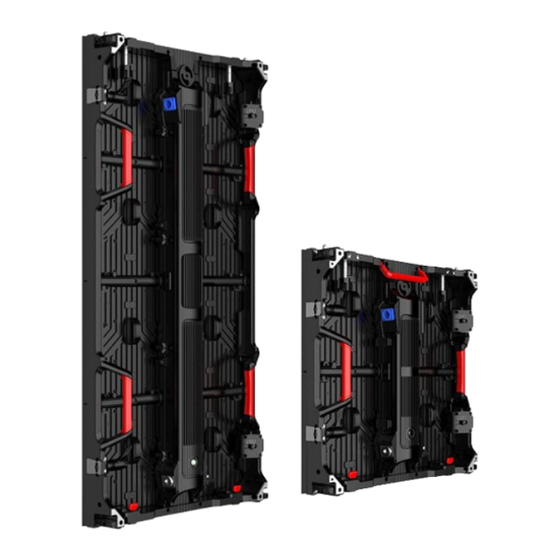
Page 3: Panel Overview
PANEL OVERVIEW 500mm 83mm 500mm 1000mm... - Page 4 PANEL OVERVIEW Positioning Pin Structure Connection Hole Vertical Lock Power Cables Port Side Lock Side Lock Adjustable Part Handle Module Power Box Testing Button Signal Cables Port Vertical Lock Releasing Button Corner Protection (Indoor Version)
-
Page 5: Parts List
PARTS LIST Description Specs Pictures Vacuum Maintenance Tool Screwdriver Level Ruler Hexagonal Wrench... - Page 6 FRONT MAINTENANCE 1. MODULES MAINTENANCE 1. Take off the problem module by vacuum maintenance tool then replace a good module. 2. POWER BOX MAINTENANCE 1. Take off all the modules by vacuum maintenance tool, release all the screws / locks of power box from the front side of cabinet, then take off the problem power box and replace a good one.
- Page 7 REAR MAINTENANCE 1. MODULES MAINTENANCE 1. Hold the handle of module then push the module out. Rotate the module to proper angle then remove it. 2. POWER BOX MAINTENANCE 1. Release all the screws / locks of the problem power box, remove the problem power box then replace a good one.
- Page 8 0.5m Base Stand Outrigger 1m Base Stand Clamp 0.5m Ladder 1m Ladder 1m Beam Connector...
- Page 9 STACKING 1. According to the screen size to select the base stand. Connect with outrigger and fixed by a plug. Then splice them in sequence. 2. Check and adjust the horizontal by level ruler while splicing. Make sure all base stands are on the same level.
- Page 10 STACKING 3. Assemble the first layer ladders on the base stands in order. Then fixed them by a plug. 4. Place the second layer ladders on the first layer ladders in order. Then fixed them by a plug.
- Page 11 STACKING 5. Connect the 1m beam connector with ladders to achieve horizontal connection, screw tight to ensure the stability of whole stacking structure. 6. Place the counterweights on outrigger to increase the stability of whole stacking system.
- Page 12 STACKING Front view Side view 7. Place the first cabinet on the base stand, make sure the screen side is a little bit out of base stand. 8. Place the second cabinet on the base stand, check and adjust the flatness then connect the cabinets by side locks.
- Page 13 STACKING 9. Hold the cabinets then connect the clamp to stacking structure, screw the connection plate side to cabinets. 10. Repeat the previous steps to install the first layer cabinets, make sure all the side locks have been connected, and also connect the clamps at specific locations.
- Page 14 STACKING 11. Place the second layer cabinet on the first layer cabinet, check and adjust the flatness then connect the vertical locks. 12. Place the second cabinet beside the first one, check and adjust the flatness then connect the side locks and vertical locks between cabinets.
- Page 15 STACKING 13. Hold the cabinets the connect the clamp to stacking structure, screw the connection plate side to cabinets. 14. Repeat the previous steps to install the other cabinets to finish the installation.
Need help?
Do you have a question about the EGO DISPLAY EasyRENT and is the answer not in the manual?
Questions and answers